NOVUS AUTOMATION 1/4
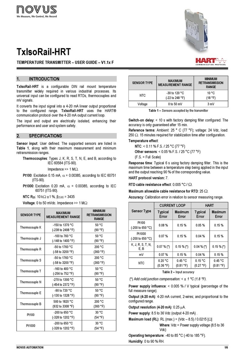
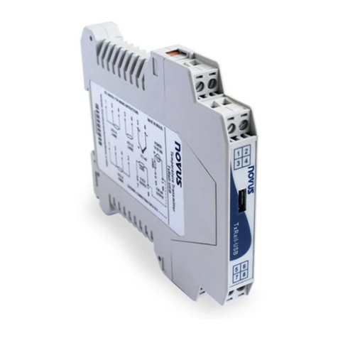
TxBlock-USB Transmitter
TEMPERATURE TRANSMITTER - OPERATING MANUAL –V1.0x F
INTRODUCTION
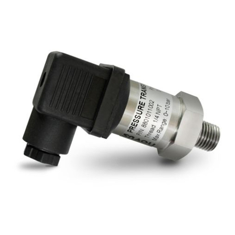
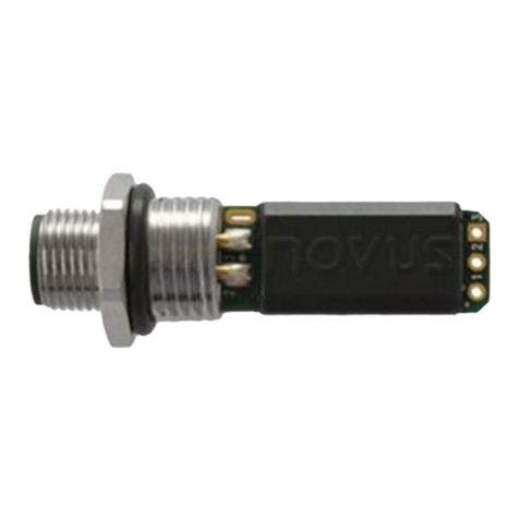
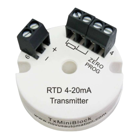
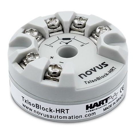
The TxBlock-USB is a 4-20 mA 2-wire temperature transmitter for
head mount, powered by the current loop. The output current is
linearized and adjusted in fuction of the input sensor type and range
configured.
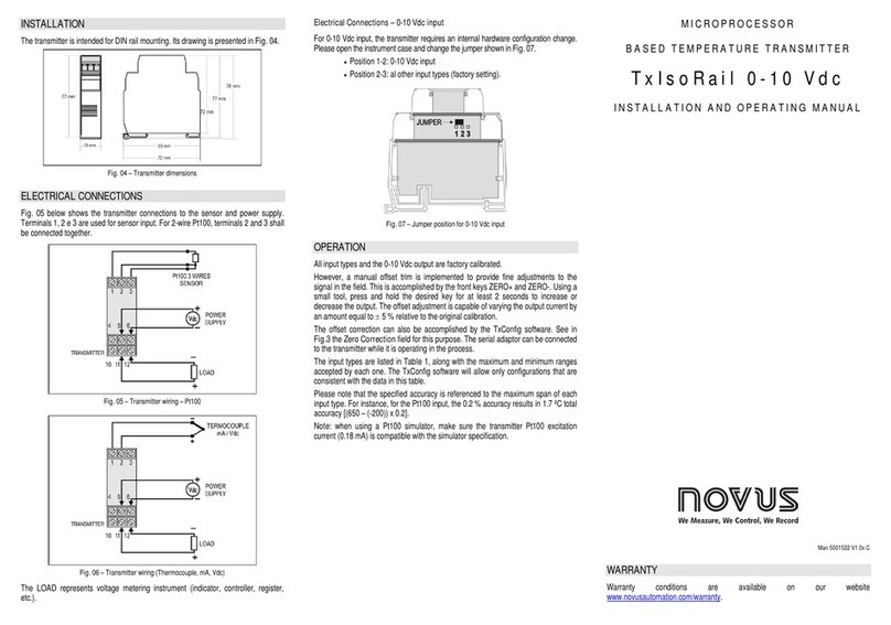
Its configuration is accomplished by connecting the transmitter to a
PC USB port without the need of any dedicated interface. The
configuration does not require that the transmitter be powered.
SPECIFICATIONS
Sensor input: User defined. The supported sensors are listed in
Table 1, along with their maximum ranges.
Thermocouples: Types J, K, R, S, T, N, E and B accoding to
IEC 60584 (ITS-90). Impedance >> 1 M
Pt100: Type 3-wire, Excitation 0.8 mA, = 0.00385,
according IEC 60751 (ITS-90).
For 2-wire sensors, tie terminals 3 and 4
together.
Pt1000: Type 3-wire, Excitation 0.17 mA, = 0.00385,
according IEC 60751 (ITS-90).
For 2-wire sensors, tie terminals 3 and 4
together.
NTC R25°C: 10 k±1 %, B25/85 = 3435
Voltage: 0 to 50 mVdc. Impedance >> 1 M
Maximum Measurement
Range
Minimum Measurement
Range
Table 1 –Sensors accepted by the transmitter
Switch-on delay: < 2.5 s. The accuracy is only guaranteed after 15
min.
Terms of reference: ambient: 25 ° C; voltage: 24 Vdc, load: 250 ;
settling time: 10 minutes.
Temperature Effect: < ±0.16 % / 25 °C
Response time: typical 1.6 s.
Maximum voltage allowed at input terminals no sensor: 3 V.
RTD current: 800 A.
RTD cable resistance effect: 0.005 °C /
Maximum allowable cable resistance for RTD: 25 .
Pt100 / Pt1000
(-150 to 400 °C)
Pt100 / Pt1000
(-200 to 650 °C)
mV, K, J, T, E, N, R, S, B
Table 2 –Calibration error, percentage of the full measurement range
(*) Add cold junction compensation: < ± 1 °C.
Power supply influence: 0.006 % / V typical (percentage of the full
measure range).
Output:4-20 mA or 20-4 mA current, 2-wired; linear in relation to the
temperature measurement by the selected sensor.
Output Resolution: 2 A.
Power supply: 10 to 35 Vdc, across the transmitter;
Maximum load (RL): RL (max.) = (Vdc –10) / 0.02 []
Where: Vdc= Power supply voltage (10-35 Vdc)
Operating Temperature: -40 to 85 °C
Humidity: 0 to 90 % RH
Electromagnetic Compatibility: EN 61326-1:2006
No electrical isolation between input and output.
Internal protection against polarity inversion.
Cold junction compensation for thermocouples.
Dimensions: 43.5 mm (diameter) x 20.5 mm (height)
Connection Wire Cross Section: 0.14 a 1.5 mm²
Screw Tightening: 0.8 Nm.
Housing: ABS UL94-HB.
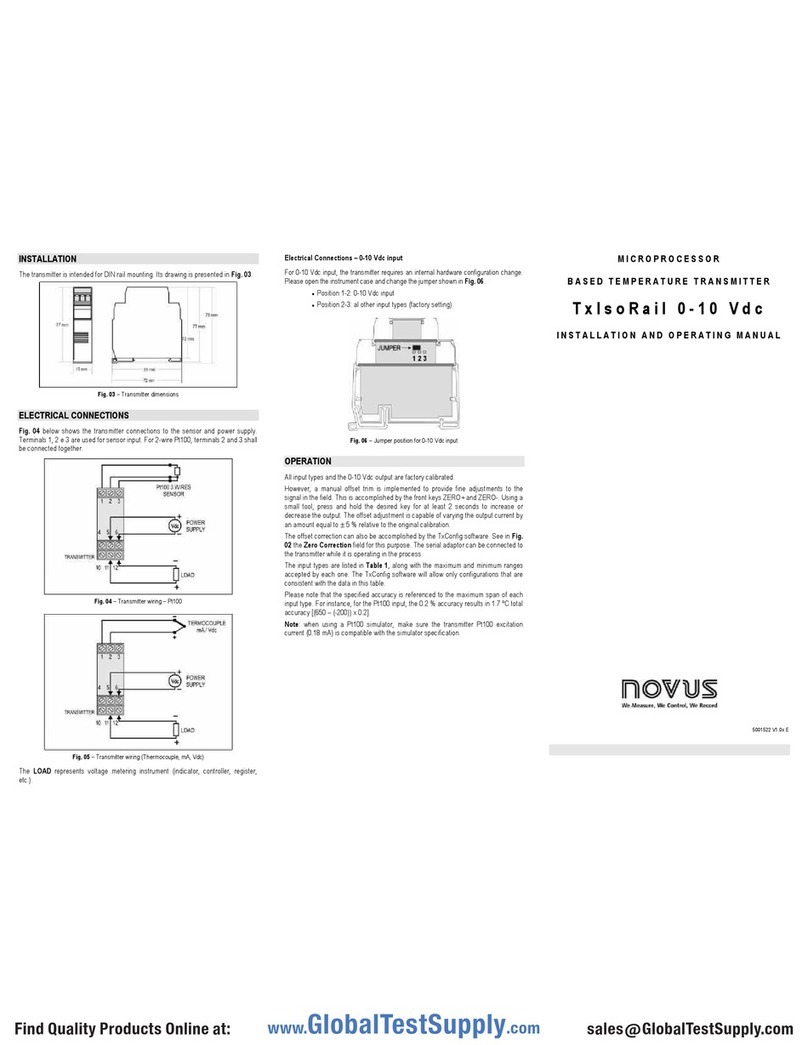
CONFIGURATION
When the trasmitter is used with the factory setting, no further action
is required and the transmitter is ready to be installed. Changes to
the configuration are possible through the TxConfig II software,
provided free of charge.
The TxBlock-USB Setup Kit consisting of the Txconfig II software and
USB cable can be purchased from the manufacturer or any authorized
distributor. The Txconfig II software is continuously updated and new
versions can be downloaded at no charge from the manufacturer’s
website. To install, execute the TxConfigIISetup.exe file and follow the
instructions.
Fig. 1 –USB cable connection
