AUTEM PLC-ANALYZER pro 6 User manual

PLC-ANALYZER pro
6 -
Driver Addendum
PILZ PSS / PNOZ - Ethernet TCP/IP
PILZ PSS / PNOZ - programming interface
Copyright © 1993 - 2022 AUTEM GmbH. All rights reserved. No part of this user manual, including excerpts, may
be reproduced, photocopied or electronically stored without the expressive written permission of AUTEM.
The software described in this manual is subject of a software license agreement and may only be used
according to the terms of this agreement.
AUTEM GmbH
Dithmarscher Straße 29
26723 Emden
Germany
+49 4921 9610 0
www.autem.de
AUTEM does not give any warranty for this manual as well as no express or tacit warranties on commercial
quality and suitability for a particular use. AUTEM does not take over adhesion for errors contained in it or for
damages that may occur as a result of using or applying this material.
The soft and hardware designations mentioned in this book are in most cases also registered trademarks and
are subject to the legal regulations as such.
For references, suggestions and improvement suggestions we are always grateful. Please send these to AUTEM.
1st Edition 2022

PLC-ANALYZER pro 6 -
PILZ PSS / PNOZ
2 / 7
Table of Contents
Signal source .................................................................................................................................................. 3
PILZ PSS / PNOZ ........................................................................................................................................ 3
Installation
.......................................................................................................................................... 3
Installing additional hardware ......................................................................................................... 3
Installing additional software .......................................................................................................... 3
Configuration
....................................................................................................................................... 4
Data acquistion .................................................................................................................................... 6
Supported PLC models and CPUs ..................................................................................................... 6
Recordable PLC addresses ............................................................................................................... 6
Number of recordable addresses .................................................................................................... 6
Time behaviour and particularities .................................................................................................. 7

PLC-ANALYZER pro 6 -
PILZ PSS / PNOZ
3 / 7
Signal source
PILZ PSS / PNOZ
This driver addendum describes the particularities of the following PLC drivers and gives you hints on
using them.
PILZ PSS / PNOZ - Ethernet TCP/IP
PILZ PSS / PNOZ - programming interface
With the PLC driver "PILZ PSS / PNOZ - Ethernet TCP/IP" PLC signals can be acquired via Ethernet (TCP/IP)
and the PLC driver "PILZ PSS / PNOZ - programming interface" via the serial communication port of the
PLC.
It is important that you read through the driver addendum before using a PLC driver. Please pay
attention to the WARNINGS that advise you on possible dangers when using PLC-ANALYZER pro.
!WARNING
Errors that may occur in the automated facility, endangering humans or causing large-
scale material damage, must be prevented by additional precautions. These precautions
(e.g. independent limit monitors, mechanical interlocks) must guarantee safe operation,
even in case of dangerous errors.
Installation
The PLC driver can be added to the project as a new signal source. If the driver you want is not yet in the
list of available signal sources, you must first activate the license for the PLC-driver with the AUTEM
LicenseManager on your computer.
Installing additional hardware
If you have already connected your PC to the PLC via a TCP/IP network or a serial cable, you normally do
not need to do anything else. Otherwise, connect your PC to the PLC.
Installing additional software
No software is required in addition to the PLC-ANALYZER pro basic module and the PLC driver.
PLC-ANALYZER pro 6 -
PILZ PSS / PNOZ
4 / 7
Configuration
Open driver settings
to set important parameters for data recording. If you have added the driver to the
project several times, you can set the properties individually for each individual driver.
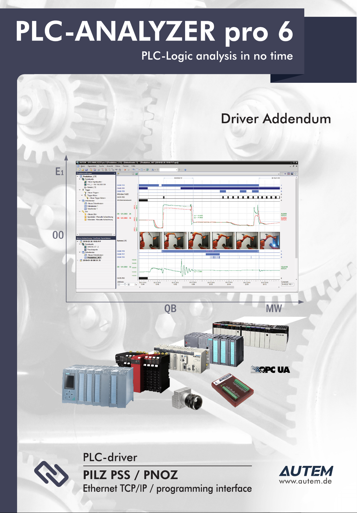
Fig. 1-1 Settings PILZ PSS - Ethernet TCP/IP
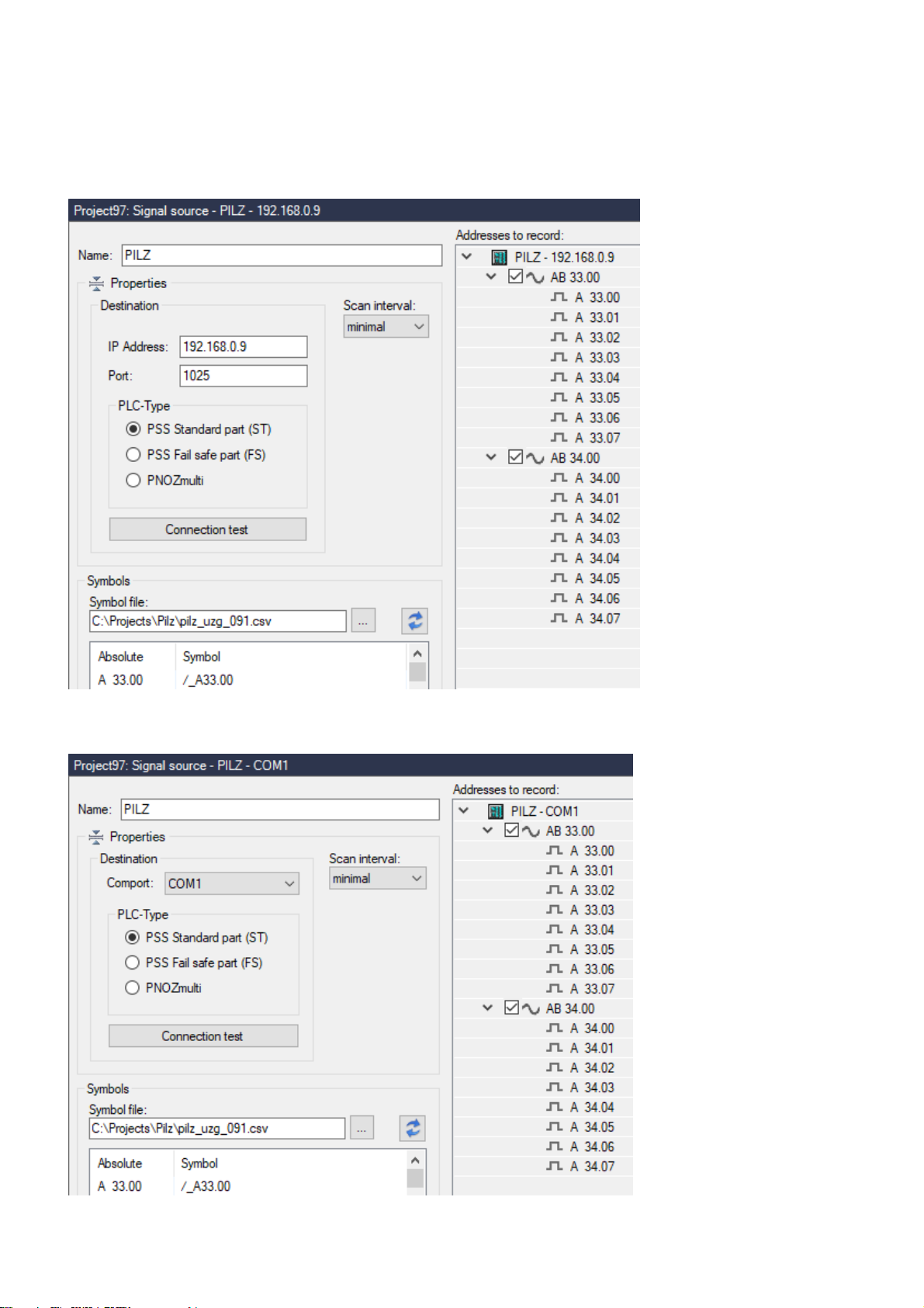
Fig. 1-2 Settings PILZ PSS - Ethernet TCP/IP

PLC-ANALYZER pro 6 -
PILZ PSS / PNOZ
5 / 7
First give the driver a meaningful
name
. Then set the IP Address and the
Port
of the PLC or the
Comport
to which the PLC is connected. These settings can be found in the configuration of your PSS WIN-PRO
project.
Under PLC type, specify whether you want to record data from the Standard part or from the
Fail-safe
part
of a PSS CPU or from a
PNOZmulti.
Press
Connection test
to check, whether a connection to the PLC can be established.
Under Scan interval
you specify the time interval at which measured values are read out from the PLC. A
longer sampling interval can be selected for signal paths that are not time-critical, e. g. temperature. As
a result, the generated signal files become smaller.
Under Symbols, select a Symbol file to make the symbols available for address selection. This makes it
possible to use symbolc identifiers when entering addresses. In addition to the absolute address, the
symbolic identifier and comment are also displayed and stored in a signal- or project file.
After setting the communication properties, add the PLC signals to be recorded. When a symbol file is
loaded, the signals to be recorded can be conveniently selected from the symbol list by double-click or
drag and drop.

PLC-ANALYZER pro 6 -
PILZ PSS / PNOZ
6 / 7
Data acquistion
Supported PLC models and CPUs
All models of the PILZ PSS 3000 series and the PNOZmulti are supported, which support a connection to
the programming software (PILZ Win-PRO) via the corresponding interface.
Recordable PLC addresses
The following table shows the recordable addresses and the corresponding address syntax:
Syntax
Address type
Example
A y.z
PSS output byte y, bit z
A 32.4
AB y.z
PSS output byte y
AB 9.24
AW x.z
PSS output word x.z
AW 14.00
E y.z
PSS input byte y, bit z
E 17.23
EB y.z
PSS input byte y.z
EB 23.24
EW x.z
PSS input word x.z
EW 14.16
O y.z
PNOZ output byte y, bit z
O 32.4
OB y.z
PNOZ output byte y
OB 9.24
OW x.z
PNOZ output word x.z
OW 14.00
I y.z
PNOZ input byte y, bit z
I 17.23
IB y.z
PNOZ input byte y.z
IB 23.24
IW x.z
PNOZ input word x.z
IW 14.16
M y.z Flag byte y, bit z M 3.07
MB y.z Flag byte y.z
MB 25.08
MW x.z
Flag word x.z MW 24.16
T x
Status Timer x T 2
Z x
Status Counter x
Z 5
ZW x
Counter x
ZW 5
y DL x
Left data byte x from DB y
82 DL 622
y DR x
Right data byte x from DB y
24 DR 346
y DW x
Dataword x from DB y
12 DW 600
Table 1-1 Address syntax PILZ PSS / PNOZ
Number of recordable addresses
A maximum of 16 million addresses can be acquired from up to 250 signal sources.

PLC-ANALYZER pro 6 -
PILZ PSS / PNOZ
7 / 7
Time behaviour and particularities
+
NOTE
Acquiring data with PLC-ANALYZER pro results in a small increase in cycle time in the
PLC to the same manner as it happens with programming software PSS WIN-PRO in
the online-mode.
The intervals between scan transfers from the PILZ PLC to the computer are depending on the following
items:
CPU type
cycle time of PLC
Number of recorded addresses.
For the PSS SB 3006-3 ETH-2 the scan interval for a address is approximately 5 ms, i.e. for a cycle time > 5
ms there is one scan for each cycle. For a longer PLC cycle time data transfer is synchronized with the PLC
cycle. For a shorter cycle time the computer does not obtain a scan for each cycle, resulting in a partial
loss of information. This loss can be compensated by repeated measurements of the interesting signals.
Every additional requested address leads to an increase in scan time of about 0.1 ms. The following
table exemplarily shows some values of time behaviour during acquisition:
Requested data Scan time
1 flag byte
5 ms
50 flag words
11 ms
100 flag words
22 ms
1 flag byte, 1 output byte
5 ms
50 flag byte, 50 data words
23 ms
10 flag words, 10 data words, 10 inputs, 10 outputs
10 ms
Table 1-2 Scan times on PSS SB 3006-3 ETH-2
The following table shows typical scan times for PILZ PSS 3046 (cycle time ca. 40ms):
Scandata Scan time
1 Byte
90 ms
32 Words
120 ms
Table 1-3 Recording time PILZ PSS 3046
Table of contents
Other AUTEM Industrial Equipment manuals


