Auto Anchor AA570 User manual

AutoAnchor 570

2

3
AutoAnchor 570 Owner’s Manual
Part 1 Important Information 4
Part 2 Installation 7
Part 3 Set Up 18
Part 4 Operation 30
Part 5 Maintenance 36
Part 6 Troubleshooting 37
TABLE OF CONTENTS
To the best of our knowledge the information in this manual was correct at the time
of printing. However,the AutoAnchor products are continuouslybeing reviewed
and improved and product specications may be changed without notice. The
latest product specications may not be reected in this version of the manual. The
documentation relating to the AutoAnchor products is created in the English language
and may be translated from English to another language. In the event of any conict
between translated documents, the English language version will be the ofcial version.
AutoAnchor documents are available on www.autoanchor.co.nz

4
•The AA570 should only be installed by a qualified marine electrician. Do not
attempt to install the AA570 unless you are suitably qualified.
• ThismanualsupportstheuseoftheAA570only.Theappropriatemanufacturer’s
instructionsmustbefollowedfortheinstallationanduseofthewindlassitisset
uptocontrol.
• Theremustbeanalternativemethodavailabletooperatethewindlass.
•The AA570 can be fitted to most vertical windlasses. A horizontal windlass may
requireasensorholderoracustomdesignedsensorwhichisnotincludedinthe
standardpack.CheckwithyoursupplierortheAutoAnchormanufacturer.
•The AA570 must be fitted to a windlass with a dual direction control box or
solenoidpack.
• InformationforinstallationandoperationoftheAA570issupplied,including
pre-set windlass prole lists, wiring diagrams, the Owner’s Manual and
theQuickUserGuide.All documents must be left on board for the owner.
• Noncompliancewiththeinstructionscouldimpairthewindlassandthe
AA570operation,andcouldresultinpersonalinjuryand/ordamagetotheboat.
• Noncompliancewiththeinstructionswillnegatethemanufacturer’swarranty.
• TheAA570manufacturerandsupplieracceptnoliabilityforpersonalinjuryor
propertydamageresultingfromfailuretofollowtheinstallationandoperation
instructionsortheuseoftheAA570inawaythatmaycauseaccidentsor
damageorthatmayviolatethelaw.
•All the technical and cable specications must be checked and adhered to.
•Wiring diagrams must be followed without modication.
• BeforeusetheAA570mustbecorrectlysetupforthewindlassitistocontroland
testedinasafeenvironment.TheAA570willnotcountcorrectlyifthewindlass
selectioniswrongorthewindlassisnotstandard(egitisinstalledwithadifferent
chainwheelormotor).
•All installations must be carried out in accordance with USCG, ABYC, NMMA and
BMEA requirements.
• Whenthisproductreachestheendofitsusefullifeitmustbedisposedofin
accordancewithlocalregulations.
PART 1 IMPORTANT INFORMATION
READ BEFORE INSTALLING OR USING THE AUTOANCHOR

5
TECHNICAL SPECIFICATIONS AA570
Parameter AA570 Remote Console AA702 Base Station
Power Supply 12V/24V DC
Maximum Voltage 30V dC
Current Consumption 50mA
Output Maximum
Current Draw
12V DC: 3.5A
24V DC: 3.5A
The system has internal current
limiting and thermal shutdown.
Output Minimum
Current Draw
12V DC: 10mA
24V DC: 20mA
IP Rating IP67 IP67
Operating Temperature
Range
23oF to 140oF (-5oC to 60oC) 23oF to 140oF (-5oC to 60oC)
Wireless Transmission 2.4GHz ISM Band, IEEE 802.15.4 Compliant, 64 Bit Unique ID
Wireless Range Typical Minimum 10m (30ft). Range depends on installation.
System Supports Up to 3 base stations and 3 consoles
Rode - Chain Only Stainless or galvanised steel.
Rode - Rope and Chain Must have a minimum of 10ft (3m) of chain. Chain must be
galvanised steel. Rope should be a good quality, nylon anchor
rope. Type 66 or equivalent.
DC windlasses require a dual direction solenoid
12V/24V DC
30V dC
50mA
12V DC: 3.5A
24V DC: 3.5A
12V DC: 10mA
24V DC: 20mA
AA570 equipment (AA702 base station, AA710 remote and AA570 console) must be
installed least 3ft (1m) away from any equipment transmitting or cables carrying radio signals
eg VHF radios, modified sine wave inverters, cables and antennas or radar antennas; and at
least 6ft (2m) away from any SSB equipment. AA702 cables must be installed at least
1.5ft (500mm) away from such items.
Tips For Optimal Wireless Connectivty
base station must be positioned to avoid this or an antenna can be tted.
Contact your supplier or the AutoAnchor manufacturer for options.
Best reception for wireless signal is from top side of base station. See diaram page 14.
Alloy, steel or carbon fibre will restrict the wireless communication. The AA702

6
RAdIO FREqUENCy COMPLIANCE
FCC Information:
This device complies with Part 15 of the FCC Rules. Operation is subject to the following
two conditions: (1) this device may not cause harmful interference and (2) this device must
accept any interference received, including interference that may cause undesired
operation.
Modications not expressly approved by the manufacturer could void the user’s authority to
operate this equipment.
This device generates, uses, and can radiate radio frequency energy and, if not installed
and used in accordance with the manufacturer’s instructions, may cause harmful
interference to radio communications.
ESTI Information (CE):
This device is compliant with the essential requirements of the R&TTE Directive 99/5/EC,
meeting the European harmonized EMC and low-voltage/safety standards.
ELECTROMAGNETIC COMPATIBILITy (EMC)
FCC Information:
This device complies with CFR47 Part 15 of FCC Rules for Class B equipment.
ESTI Information (CE):
This device meets the relevant standards set out in European Standard EN 60945:2002 for
maritime navigation and radio communication equipment and systems. These standardsThese standards
are intended to provide reasonable protection against interference by other emission
generating products on the boat. Compliance with these standards is no guarantee that
interference will not occur in a particular installation. The installation instructions must be
followed to minimise the potential for interference.
Note: If shielded cable is not used for the sensor connections this will compromise the
EMC and may invalidate the warranty.
AA570 equipment (AA702 base station, AA710 remote and AA570 console) must be
installed least 3ft (1m) away from any equipment transmitting or cables carrying radio signals
eg VHF radios, modified sine wave inverters, cables and antennas or radar antennas; and at
least 6ft (2m) away from any SSB equipment. AA702 cables must be installed at least
1.5ft (500mm) away from such items.

7
PART 2 INSTALLATION
2.1 MAGNET AND SENSOR INSTALLATION
PLEASE READ BEFORE COMMENCING INSTALLATION
Correct magnet and sensor installation is critical for successful AutoAnchor
operation.
The AutoAnchor can be installed on vertical windlasses, drum winches and most
horizontal windlasses. Installation differs depending on the windlass type and on the
rode (all-chain or rope and chain). Please follow the instructions for your windlass
and rode. If it is not possible to comply with these instructions please check with the
AutoAnchor manufacturer or your supplier for other options or if you are not sure how to
proceed.
See www.autoanchor.co.nz for contact information.
2.1.1 MAGNET INSTALLATION OVERVIEW
Check before starting: Your chainwheel may be pretted with a magnet or predrilled
ready for you to t the magnet.
Magnet Polarity: Not relevant when using the grey AA sensor (#9067) or a reed switch
sensor. If retrotting, using the black AA sensor (#9008) the south pole (marked side) of
the magnet must face the sensor.
Magnet Seal: Insert the magnet into the hole and cover it with a minimum of 1mm of epoxy
to protect it against corrosion.
Magnet Size and Position: Refer to the instructions for your specic windlass type.
2.1.2 SENSOR INSTALLATION OVERVIEW
Vertical Windlasses: The sensor is tted in the deckplate. Some deckplates are predrilled
for the sensor. Others have a dimple or mark to show where the sensor should be tted.
If the windlass is not factory drilled, drill a hole 10.3mm (13/32”) diameter through the
windlass deckplate. See the instructions for your specic windlass type.
Horizontal Windlasses: Sometimes it is not possible to t the sensor to a horizontal
windlass or it may need to be tted by the windlass manufacturer. Before starting
check with the AutoAnchor manufacturer or supplier that it is possible to t the
sensor to your windlass. You may need a special tting.
Drilling the Deck: Before drilling into the deck, ensure there is nothing below the deck that
could be damaged and that any hole you drill will not weaken the boat’s structure. Drill a
hole 10.3mm (13/32”) diameter through the deck. Ensure this hole is directly in line with the
sensor hole in the deckplate.

8
Part #9507 Male Field Connector
Part #9508 Female Field Connector
If there is no plug on the sensor cable attach the AA eld
connector to the wires and use the connecting cable as above.
2.1.4 PLUG AND PLAY SENSOR CABLE
The AutoAnchor plug and play sensor cable is 2 core tinned shielded cable. It must be
used to connect the sensor to the console unit. Ensure the connectors are rmly screwed
together.
The warranty does not apply if the sensor cable plugs are removed.
The sensor cable is tted with a female plug to connect direct to the male connector on the
AA702 base station. If a longer length is required, sensor connecting cable, with a male
plug at each end, is available in the following lengths:
6.5 m (21.33 ft) Part #9500
10 m (32.81 ft) Part #9501
15 m (49.21 ft) Part #9502
20 m (66.62 ft) Part #9503
25 m (82 ft) Part #9504
35 m (114.83 ft) Part #9514
A 2m male/female cable (Part #9505) plus a gender changer (Part #9510) will be required
to connect the extension cable to the base station.
Field Connectors
Sensor Connection: The sensor is plugged direct into the AA702 base station. Do not
leave the cable hanging loose, it must be tied in place with cable ties. Extension cable,
gender changers and eld connectors are available if required.
Sensor Plug
Fitting the Sensor: Do not force the sensor into the hole. Hammering the sensor head
can damage the internal electronics. Ensure the sensor head is positioned so that it will not
be hit by the chainwheel during windlass operation and that it is at least 300mm (1ft) away
from the battery and motor cables. Secure the sensor using a good quality neutral cure
silicone or a strong adhesive eg. Sikaex 291 or 3M 5200.
Connecting 2 cables together:
If you need to extend the cable length - 2 cables can be joined
together using Part #9510 Gender Changer.
Antenna Plug
9
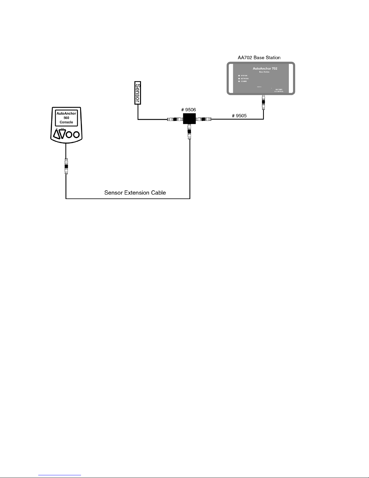
Dual Installation with Other AA Products
Use the T adaptor Part #9506 and the 2m Male/Female extension cable
Part #9505.
2.1.5 REED SWITCH SENSORS
Some windlasses are supplied pre-tted with a reed switch sensor. Reed switch sensors
must have a 10mm x 8mm magnet (#9061) and the gap between the reed switch sensor
and the magnet must be a minimum of 3mm and a maximum of 5mm. This sensor requires
a eld connector.
The AutoAnchor will operate with a reed switch sensor for all-chain rode. If using
combination rope and chain rode the reed switch sensor provides a reasonably accurate
count of rode deployed but on retrieval the display may be incorrect because it cannot
allow for the stretch in the rope.
For an accurate rope and chain count, the reed switch sensor should be replaced with the
AA grey sensor (#9067).
2.1.6 SENSOR TUNING
When the AutoAnchor is completely installed the sensor must be tuned. See the
instructions on page 28.

10
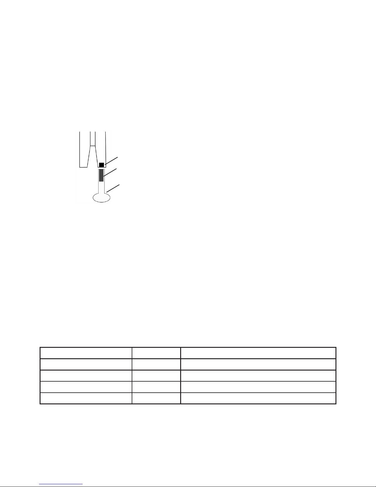
Magnet Fit: Drill a hole 10.3mm (13/32”) diameter and 9.5mm (3/8”) deep to t the
magnet in the underside of a spoke in the bottom of the chainwheel. Cover the magnet
with a minimum of 1 mm epoxy. The magnet should be aligned with the sensor. See Fig 1.
2.1.7 INSTALLATION ON A VERTICAL WINDLASS - CHAIN ONLY
Magnet Size: Standard size is 10mm x 8mmm (#9061). This may be replaced with the
smaller 6mm x 4mm (#9009) magnet if required for your windlass.
Fig 1 - All sensors
Seal with minimum 1mm epoxy.
Magnet
Sensor
Gap Between the Sensor and Magnet:
Sensor Magnet Size Gap
AA Grey Sensor #9067 6mm x 4mm Minimum 3mm - Maximum 30mm
AA Grey Sensor #9067 10mm x 8mm Minimum 3mm - Maximum 50mm
AA Black Sensor #9008 All Magnets Minimum 3mm - Maximum 8mm
Reed Switch Sensor 10mm x 8mm Minimum 3mm - Maximum 5mm
Chainwheel
Deckplate
Refer to the Overview Notes on page 4before starting installation.
Sensor Connection: Ideally the sensor should be plugged directly into the AA702 base
station. If longer cable is required use the AA 2m male/female extension cable (Part
#9505) or one of the AA standard male/male extension cables plus the 2m cable and a
gender changer. Ensure the connectors are rmly screwed together.
Loose cable should be tied in place with cable ties and kept clear of chain.
Sensor Position: The AA black sensor and the reed switch sensor must be tted direclty
in line with the magnet in the chainwheel. See Fig 1 above. The AA grey sensor may be
tted up to 20mm out of alignment. The gap between the sensor and magnet must be as
per the table below.
Note: If it is not possible to
align the sensor and magnet
exactly the AA grey sensor may
be tted up to 20mm out of
alignment. The AA black sensor
and the reed switch sensor must
be directly aligned.
11
2.1.9 INSTALLATION ON A HORIZONTAL WINDLASS - CHAIN ONLY
Fig 6
Magnet in rim of chainwheel and standard
sensor in sensor holder screwed to the deck
Magnet & Sensor Fitting for Chain Only Horizontal Windlasses
Magnet Size: 6mm x 4mm magnet (#9009).
Magnet Fit: If your windlass is not predrilled drill a hole 6.5mm (1/4”) diameter and 5mm
(3/16”) deep in the edge of the chainwheel. Cover the magnet with a minimum of 1mm
epoxy.
Gap Between the Sensor and Magnet:
Sensor Magnet Size Gap
AA Grey Sensor #9067 6mm x 4mm Minimum 3mm - Maximum 30mm
AA Grey Sensor #9067 10mm x 8mm Minimum 3mm - Maximum 50mm
AA Black Sensor #9008 All Magnets Minimum 3mm - Maximum 8mm
Reed Switch Sensor 10mm x 8mm Minimum 3mm - Maximum 5mm
Sensor Connection: If longer cable is required the AutoAnchor plug and play sensor
extension cable must be used to connect the sensor to the AA702 base station. Ensure
the connectors are rmly screwed together.
Loose cable should be tied in place with cable ties and kept clear of chain.
Refer to the Overview Notes on page 4before starting installation. It is not
possible to set out a single installation method for horizontal windlasses.
The sensor may be tted inside the windlass or you may need a sensor
holder (Part #9070). See Fig 6 below. Often the sensor and magnet can only
be tted by the windlass manufacturer.
Sensor Holder
Sensor
Magnet
Sensor Position: The AutoAnchor sensor may be tted using a sensor holder xed to the
deck to sit under the chainwheel (See Fig 6). The AutoAnchor sensor holder (#9070) is not
included in the standard kit. Check with your supplier if you need this. The AA black sensor
and the reed switch sensor must be tted directly in line with the magnet in the chainwheel.
The AA grey sensor may be tted up to 20mm out of alignment. The gap between the
sensor and magnet must be as per the table below.

12
Before starting check with the AutoAnchor manufacturer, or supplier, that it is
possible to t the sensor and magnet to your horizontal windlass.
For an accurate rope count the rode must run between the sensor and magnet. On a
horizontal windlass the magnet and sensor must be tted by the windlass manufacturer.
If it is not possible to have the sensor and magnet tted to achieve this you can use the
chain only horizontal windlass installation above. This provides an accurate count of rode
deployed but during retrieval the display may be incorrect because it cannot allow for
the stretch in the rope.
2.1.10 INSTALLATION ON A HORIZONTAL WINDLASS - ROPE & CHAIN
2.1.11 INSTALLATION ON DRUM WINCHES
For Drum Winch Set Up and Operation Refer to Page 29.
Gap Between the Sensor and Magnet:
Minimum 5mm and maximum 40mm
The magnet and sensor must be tted so that the gap remains consistent as the
winch turns
Magnet Installation:
Size: 10mm x 8mm magnet (#9061)
The magnet can be mounted on the main shaft or on the side of the drum. See Figs 8 and
9. If mounted on the side of the drum, position it close to the inside to reduce the
peripheral speed of the magnet. Fix the magnet into position with epoxy ensuring it is
completely sealed to prevent corrosion.
Sensor Installation
The Grey 3 wire AA sensor (#9067) is recommended but a proximity sensor may be used.
Every installation is different so this manual can provide guidelines only. The AA sensor
holder #9070, or a customised sensor holder will be required to ensure the sensor remains
in position and the gap is consistent between the sensor and magnet during operation.
Fig 8
Sensor
Sensor Connection: The AutoAnchor plug and play sensor extension cable must be
used to connect the sensor to the AA702 base station. Ensure the connectors are rmly
screwed together.
Loose cable should be tied in place with cable ties and kept clear of chain.
Magnet on
side of drum Magnet
on shaft
Sensor
Fig 9
Magnet
Sensor
Fig 7
OD
ID

13
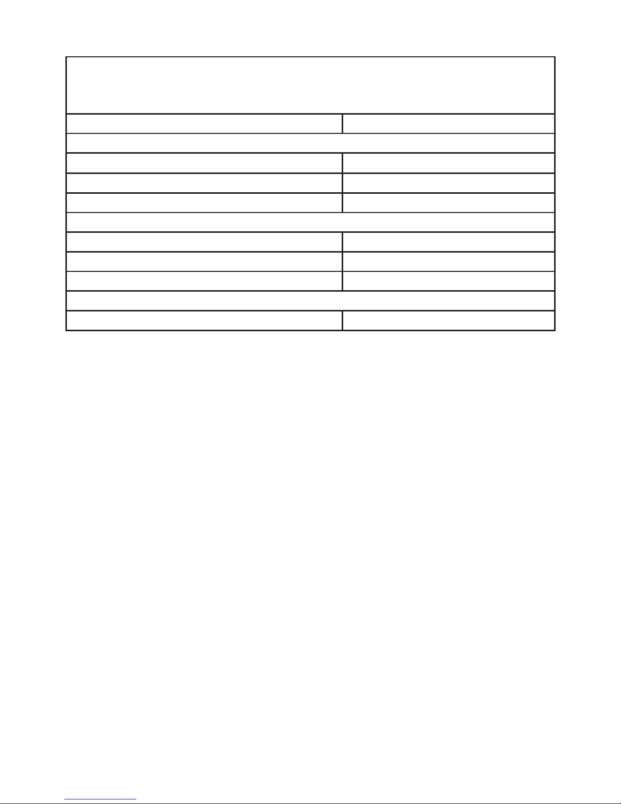
AA702
Terminal
Default Function
Assignment
Alternative Function Assignment
BATT (-) Ground
BATT (+) Positive
OUT 1 (+) 1 Windlass
Down
OUT 2 (+) 1 Windlass
Up
OUT 3 (+) 2
Port
Windlass
Option A
OUT 4 (+) 2
Starboard
Windlass
Option B
OUT 5
White
(+) 2
Port
Power Enable 3Rope/Chain
Motor Load Wires
OUT 6
Brown
(+) Thruster B (Stern)
Starboard
Dual Speed 3Rope/Chain
Motor Load Wires
2.4.1 BASE STATION INTERNAL CONNECTIONS
Notes:
Unused outputs are automatically assigned as auxiliary outputs.
All outputs are active high (+).
1Only one windlass can be connected to a base station. 2 windlasses require 2 base
stations. The windlass outputs OUT1 and OUT2 are xed, however, the
control buttons for up and down can be swapped in the set up menu as can the
location of the windlass (bow or stern).
2Stern and bow thruster output locations stated are the default locations. These can
be swapped in the set up menu. The port and starboard directions for each output
cannot be changed.
3Only required for rope/chain counting
OUT 5 = White Motor Load Wire
OUT 6 = Brown Motor Load Wire
The kit has one master base station and one remote console.
Each base station has 6 outputs. Up to 2 slave stations can be attached to the master
station to provide extra
2.4 REMOTE CONSOLE AND BASE STATION INSTALLATION
AA570
outputs.
*THRUSTER AND AUXILARY CONTROLS ONLY FUNCTION WITH AA710
HAND HELD REMOTE (AA9408 / AA9400)
*Thruster A (Bow)
*Thruster A (Bow)
*Thruster B (Stern)
2*
FOR USE ONLY WITH AA710 REMOTE.

14
2.4.2 CONSOLE INSTALLATION
The console is supplied with mounting kit and
a cover. One remote console can operate multiple
base stations.
The unit should be mounted on a flat surface
at least 3ft (1m) away from any equipment
transmitting or cables carrying radio signals
eg VHF radios, cables and antennas or radar
antenna and at least 6ft (2m) away from any
SSB equipment.
The remote console is sealed to IP67.
Up to 4 remote consoles can be connected to a system.
To maintain the IP67 waterproof seal through the
cable gland a tinned, marine grade multi core
cable must be used and the base station must be
mounted so that the cables extend below the unit
when xed to the wall.
•the lid can be removed easily during operation.
• the LED indicators can be seen during operation.
•the best reception is available (see Fig 10).
• the cables extend below the unit when xed to the wall
to avoid condensation entering through the cable gland.
LED Indicators
2.4.3 BASE STATION
Wireless Communication
Best reception for the wireless signal is on the top or sides
of the base station as per the diagram. Alloy, steel or
carbon bre will restrict the wireless communication. An
antenna may need to be tted if wireless communication is
impeded. AA727 Antenna Part # AA9403
Up to 3 base stations can be connected to a system.
When operating a windlass, the base station should be
mounted close to the windlass, in a position where:
Fig 10
B
e
s
t
r
e
c
e
p
t
i
o
n
t
o
p
o
r
s
i
d
e
s
15
12V or 24V DC power supply is required to the AA702 base station.
Check battery polarity before connecting power and ensure output terminals will not short.
Refer to the manufacturer’s specications for fuse/breaker, isolator and main power
cable specifications, for the equipment being controlled by the AA570.
Ensure any fuse/breaker on the control circuit has a rating applicable to the current loads
connected to the outputs. (AA702 Output maximum is 3.5 Amps). An additional isolating
switch should be installed for controls if the main breaker or isolator is not readily acessible
from the helm.
Multiple battery bank negative terminals must be permanently connected together to
become the common negative return (ground).
2.5.1 WINDLASS INSTALLATIONS
Power supply to the AA702 base station must be from the windlass control circuit, along
with all other windlass controls eg. toggle switch, remote switches, deck switches, other
AutoAnchor devices. Power supply must not be from the motor positive near the
windlass.
2.5.2 MULTIPLE BASE STATION INSTALLATIONS
The master base station must be powered up when using a slave base station application.
Separate base stations may be powered from separate supplies, however, if 2 products
are connected to the same base station they must be powered by the same supply,
or relays must be used as a means of isolation. To maintain power to the windlass it is
recommended that the windlass be attached to the master base station.
THE POWER SUPPLY MUST BE DISCONNECTED WHEN INSTALLING,
CONNECTING OR CHANGING THE WIRING
2.5 POWER SUPPLY
2.6 VOLTAGE LEVELS
Neither the windlass nor the AutoAnchor will operate with insufcient power. (See minimum
voltages below). Batteries must be properly maintained and charged and all connections
and wires must be of good quality and the correct gauge to prevent voltage drop.
Minimum Voltage Required 12V DC System 24V DC System
Minimum voltage required to start windlass 10V DC 20V DC
If the windlass is already operating, this is the
minimum voltage required to continue operating.
6V DC 12V DC
16
CABLE SPECIFICATIONS
An appropriate multi-core cable must be used to maintain the cable gland
seal into the base station.
Total Length Cable Size
Cable from AA702 Base Station to the Power Supply
Less than 8m (26ft) 1.5mm2(AWG16)
8m (26ft) - 11m (36ft) 2.0mm2 (AWG14)
11m (36ft) - 17m (56ft) 2.5mm2(AWG12)
Cable from AA702 Base Station to Outputs
Less than 10m (33ft) 1.5mm2(AWG16)
10m (33ft) and 20 m (66ft) 2.0mm2 (AWG14)
20m (66ft) and 40m (132ft) 2.5mm2(AWG12)
Cable from Motor Load Wires
Up to 30.5m (100ft) 1.0mm2(AWG18)
2.7 WIRING
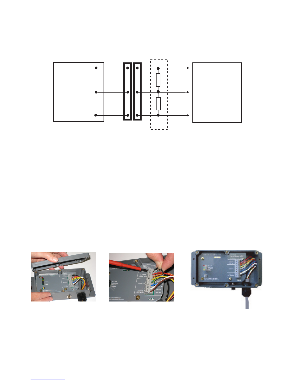
2.7.1 MOTOR LOAD WIRES (BROWN AND WHITE) OUTPUTS 5 & 6
Rope & Chain Counting: The brown and white wires must be connected direct to the
windlass motor terminals for rope & chain counting. A 1000 Ohm resister must be tted
near the motor terminal for short circuit protection. The motor load terminators supplied
in the kit have motor terminal connectors with a 1000 Ohm resistor pretted.
If the AA710 is tted to an all-chain windlass, a thruster or auxiliary equipment. Outputs
5 and 6 can be used for other options.
Interlock protection is included in the system. Do not t diodes or interlock devices to
outputs as these will prevent the system from operating correctly.
All battery and motor cables must be ring type, insulated to prevent short circuits and
installed no closer than 1ft (300mm) away from the sensor head.
To reduce the potential for interference all cables must be located at least 1.5ft (500mm)
away from any equipment transmitting or cables carrying radio signals eg VHF or SSB
radios, cables and antennas or radar antennas.
Do not leave cables hanging loose, they must be tied in place with cable ties.
2.7.2 MULTIPLE AUTOANCHOR INSTALLATIONS
It is important when wiring multiple AutoAnchor products that potential differences do not
occur along the ground connection. This can cause incorrect counting. Ensure AA560
and AA150 consoles and AA702 base stations are star grounded, and that there are no
other high current paths between consoles. All wiring for multiple installations is run in
parallel. Refer to wiring diagrams for further details.
17
2.7.4 PLUG & PLAy SENSOR CONNECTIONS
The AA701 Base Station and the sensor are pretted with connector plugs. The 2m sensor
cable plugs direct into the base station. Extension cables are available. See page 8for
plug and play sensor cable information.
2.7.6 WIRING dIAGRAMS FOR AA702 BASE STATION
Wiring diagrams are included in the kit. Please refer to them for wiring detail.
These diagrams and installation help are also available on www.autoanchor.co.nz
2.7.5 CONNECTING THE CABLES INTO THE BASE STATION
Remove the lid from the AA702 base station.
Feed the multi-core cable through the waterproof gland.
Connect the cables to the terminal block, using a screwdriver to press down and open
each terminal as required. (See the photograph below).
Tighten the cable gland.
Replace the lid.
2.7.3 CONNECTION TO LOW CURRENT dRIVES
When connecting to equipment with solid state switching or other low current drives, eg
PLC or AC variable frequency, a dummy resistor load (Part # 9515) may be required to
provide sufcient loading and to meet EMC and safety considerations. The resistor pack
should be installed close to the equipment control not on the AA702 base station.
Up
Up
Down
Down
BATT (-)
-
1
2
3
1000R
1000R
1
2
3
Low current
windlass drive
Part No
9515
AutoAnchor Product
AA150
AA560
AA601
AA710
AA730

18
3.1 USING THE AUTOANCHOR BUTTONS
Scroll: Menu/Numbers/Up/Down.
Mode/Select/Enter/Save.
On/Off/Escape or Back.
Hold together to access the Set up menu.
Hold for 2 seconds to disable the lock.
Hold for 2 seconds to return the AutoAnchor to the idle state.
PART 3 SET UP
downUp
3.2.1 SYSTEM OVERVIEW
The AA570 kit is supplied with 1 x AA570 remote console and 1 x AA702 master base
station. Each console and base station has a unique ID and the units must be registered
to each other to operate the system. If extra outputs are required up to 2 additional base
stations, known as slave stations, may be added into the system. Up to 4 consoles can be
registered to operate a system. Follow the instructions to register the consoles and base
stations.
3.2 WIRELESS INTERFACE SET UP
3.2.2 REGISTRATION SWITCH
Located inside the base station. Use to register the
base station to the console and to register a slave
to the master base station. See the instructions over.
3.2.3 LED INDICATORS
System (Red)
Steady red indicates power is on. Flashing continuously indicates registration
state is active. Times out after 5 minutes. Flashing a slow pulse indicates sensor
is connected when the windlass is turning.
Network (Green)
Steady green indicates the base station is a master station. Off indicates the base
station is a slave (See instructions to connect a slave station below).
Comms (Yellow)
Flashing indicates data is received.
Registration
Switch
19
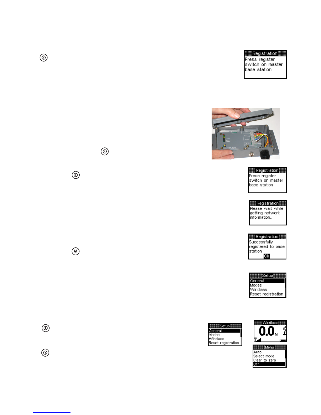
3.2.5 REGISTER REMOTE CONSOLES TO THE BASE STATIONS
Each console must be registered separately.
1. Turn off all consoles.
3. Unscrew and remove the cover from the master base station.
4. Press the Power button to turn on the remote console.
The screen will tell you to “Press the register switch on the
master base station”. NB. On first use AA570 will be on already.
5. Press and release the registration button. The green LED
will stay on. The red LED will ash to indicate the connection
is registering.
6. Registration is automatic. The screen will show that
the system is getting the network information and then
that the console has been successfully registered to the
base station. This could take up to 30 seconds.
7. Press the Mode button to select OK. The console
will return to the set up screen ready to set up the
system functions.
8. If you have more than 1 console to register to the
base station repeat the steps above ensuring the
rst console is turned off before you start.
9. When nished replace the lid on the base station.
3.2.6 TO TURN THE AA570 REMOTE CONSOLE OFF AFTER REGISTRATION
Press the to escape from Setup to
the default start up screen.
3.2.4 TURN THE AA710 SYSTEM ON FOR THE FIRST TIME
Ensure the AA702 base station is powered up.
Press the Power button on the AA570
console to turn it on. Because the system
is not yet set up, the screen will tell you to press
the registration switch on the master base station.
See instructions below to register the console to
to the base station.
Power
Press and hold the Power button for 2 seconds
to switch off.
2. Connect the power to all base stations.
20
3.2.7 Add EXTRA BASE STATIONS (S )
Slave base stations are added to supply the outputs for additional functions. All base
stations are supplied as masters and they must be reset to operate as a slave. Decide
which base station is to remain the master and then follow the directions below to register
the slave stations. Tomaintain power to the windlass it is recommended that it be attached
to the master base station.
1. Ensure all remote consoles are turned off.
2. Unscrew and remove the lid from both base stations.
3. Turn on the power to both base stations. The green LED will light up on both stations.
4. Slave: Hold down the registration button, on the slave station, for 6 seconds until the
green LED turns off. Then release the button. The red LED will ash to indicate the unit
is in registration mode.
5. Master: Press and release the registration button. The green LED will stay on. The red
LED will ash to indicate the connection is registering. Registration is complete when
the red LED stops ashing on both base stations.
6. Repeat the process to add further slave stations as required.
7. Before replacing the lids on the base stations you need to record the unique ID number
for each base station. The ID is on the white label next to the registration switch.
This number is the same as the last 4 digits on the bar code label on the outside of the
base station.
Master Base Station ID ______________
Slave Station 1 ID ______________
Slave Station 2 ID ______________
Note: The console will automatically update and register the additional slave
station when it is next turned on.
801D
Base Station ID
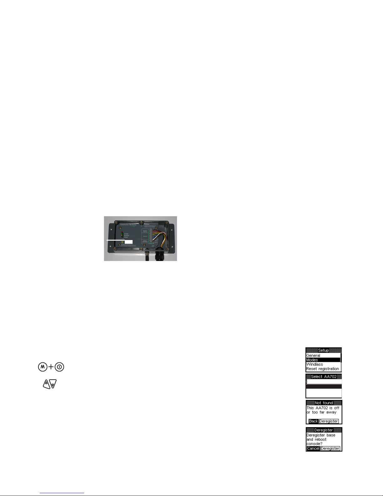
3.2.8 dEREGISTERING A BASE STATION
If a base station is removed or replaced it must be deregistered from the system. To do
this:
Turn the power off to the affected base station and disconnect it. Record the ID number.
Power up the master base station. Turn off the AA
Hold together to display the Set Up Menu. It may take up to
20 seconds for the network information to be updated.
Select Modes.
Scroll to the base station ID.
Select the base station. The screen will show Not Found.
Select Deregister.
Select Deregister again. This will remove the registration
and restart the system.
If you have deregisterered a slave station no further action is required.
If you have deregistered a master base station the system must be set up again as if it is a
new system.
815A
803D
AA570
LAVES )FOR TWINWINdLASS
This manual suits for next models
1
Table of contents
Other Auto Anchor Marine Equipment manuals


