Auto Anchor 560 User manual

OWNER’S MANUAL
AutoAnchor 560

AutoAnchor 560 Owner’s Manual
Part 1 Important Information 2
Part 2 Installation 4
Part 3 Set Up 14
Part 4 Operation 20
Part 5 Maintenance 23
Part 6 Troubleshooting 24
Index 27
TABLE OF CONTENTS
To the best of our knowledge the information in this manual was correct at the time
of printing. However, the AutoAnchor products are continuously being reviewed
and improved and product specications may be changed without notice. The
latest product specications may not be reected in this version of the manual. The
documentation relating to the AutoAnchor products is created in the English language
and may be translated from English to another language. In the event of any conict
between translated documents, the English language version will be the ofcial version.
AutoAnchor documents are available on the website www.autoanchor.co.nz
1

• The AA560 should only be installed by a qualied marine electrician. Do not
attempt to install the AA560 unless you are suitably qualied.
• This manual supports the use of the AA560 only. The appropriate manufacturer’s
instructions must be followed for the installation and use of the windlass it is set
up to control.
• There must be an alternative method available to operate the windlass .
• The AA560 can be tted to most vertical windlasses. A horizontal windlass may
require a sensor holder or a custom designed sensor which is not included in the
standard pack. Check with your supplier or the AutoAnchor manufacturer.
• The AA560 must be tted to a windlass with a dual direction control box or
solenoid pack.
• Information for installation and operation of the AA560 is supplied, including
pre-set windlass prole lists, wiring diagrams, templates, the Owner’s Manual and
the Quick User Guide. All documents must be left on board for the owner.
• Non compliance with the instructions could impair the windlass and the
AA560 operation, and could result in personal injury and/or damage to the boat.
• Non compliance with the instructions will negate the manufacturer’s warranty.
• The AA560 manufacturer and supplier accept no liability for personal injury or
property damage resulting from failure to follow the installation and operation
instructions or the use of the AA560 in a way that may cause accidents or
damage or that may violate the law.
• All the technical and cable specications must be checked and adhered to.
• Wiring diagrams must be followed without modication.
• Before use the AA560 must be correctly set up for the windlass it is to control and
tested in a safe environment. The AA560 will not count correctly if the windlass
selection is wrong or the windlass is not standard (eg it is installed with a different
chainwheel or motor).
• All installations must be carried out in accordance with USCG, ABYC, NMMA and
BMEA requirements.
• When this product reaches the end of its useful life it must be disposed of in
accordance with local regulations.
PART 1 IMPORTANT INFORMATION
READ BEFORE INSTALLING OR USING THE AUTOANCHOR
2

ELECTROMAGNETIC COMPATIBILITY (EMC)
FCC Information:
This device complies with CFR47 Part 15 of FCC Rules for Class B equipment.
ESTI Information (CE):
This device meets the relevant standards set out in European Standard EN 60945:2002 for
maritime navigation and radio communication equipment and systems. These standardsThese standards
are intended to provide reasonable protection against interference by other emission
generating products on the boat. Compliance with these standards is no guarantee that
interference will not occur in a particular installation. The installation instructions must be
followed to minimise the potential for interference.
The AA560 console must be installed at least 3 ft (1m) away from any equipment
transmitting or cables carrying radio signals eg VHF radios, cables and antennas or radar
antennas; and at least 6 ft (2m) away from any SSB equipment. AA560 cables must be
installed at least 1.5ft (500mm) away from such items.
3
Parameter
Power Supply 12V/24V DC
Current Consumption 70mA
Output Current Draw Maximum 4 Amp
IP Rating IP67 from the front provided the unit is mounted so the back is
protected from moisture
Maximum Voltage 30V DC
Operating Temperature
Range
23oF to 140oF (-5oC to 60oC)
TECHNICAL SPECIFICATIONS AA560

PART 2 INSTALLATION
The windlass must be installed according to the windlass manufacturer’s instructions with
the correct size rope and chain. It must also be regularly serviced and lubricated. For
smooth operation, the windlass requires a good quality bow roller and a swivel where the
anchor joins the chain.
RODE
Combination Rope and Chain Rode: must have a minimum of 10 ft (3 m) of chain. Chain
must be galvanised steel. Rope should be a good quality, nylon anchor rope. Type 66 or
equivalent.
Chain Only Rode: can be stainless or galvanised steel.
MAGNET AND SENSOR INSTALLATION
Critical to Operation: Correct magnet and sensor installation is critical to windlass
operation using the AA560. If it is not possible to comply with these instructions please
check with the AutoAnchor manufacturer or your supplier for other options. Some
windlasses are predrilled for sensor and magnet tting.
Reed Switch Sensors: Some windlasses are supplied pre-tted with a reed switch
sensor. Reed switch sensors can only count the revolutions of the chainwheel. This works
for a chain only windlass but it does not provide an accurate count for rope and chain rode.
If you use a reed switch sensor with rope and chain, the display may read zero when there
is rode still deployed. For an accurate rope and chain count, the reed switch sensor should
be replaced with the AA grey sensor (#9067). Reed switch sensors must have a 10mm x
8mm magnet (#9061) and the gap between the reed switch sensor and the magnet must
be a minimum of 3mm and a maximum of 5mm.
Magnet Fit: If your chainwheel is not predrilled,
drill a hole 6.5mm (1/4”) diameter and 5mm
(3/16”) deep to t the magnet in the underside
of a spoke in the bottom of the chainwheel. The
magnet must be aligned with the sensor.
See Fig 1.
Magnet Seal: Insert the magnet into the hole and
cover it with a minimum of 1mm of epoxy to seal
it from salt water. Failure to do this will impair the
magnet’s strength and durability.
MAGNET INSTALLATION FOR VERTICAL WINDLASSES
Magnet Size: 6mm x 4mm magnet (#9009).
A larger magnet may be used. Check with
your supplier.
Vertical Windlasses Using Chain Only Rode
Fig 1
Seal with minimum 1mm epoxy.
Magnet
Sensor
4

Sensor
Magnet
Gap Between the Sensor and Magnet:
Grey AutoAnchor Sensor (#9067):
6mm x 4mm Magnet (#9009): Minimum 3mm and Maximum 30mm
10mm x 8mm Magnet (#9061): Minimum 3mm and Maximum 50mm
Black 2 wire AutoAnchor Sensor (#9008): Minimum 3mm and Maximum 8mm
Reed Switch 2 wire Sensor: Minimum 3mm and Maximum 5mm
(Must use a 10mm x 8 mm magnet)
Magnet Polarity: Not relevant when using the grey AA sensor (#9067) or a reed switch
sensor. If retrotting, using the black AA sensor (#9008) the south pole (white side) of the
magnet must face the sensor.
Vertical Windlasses Using Rope and Chain Rode
The rode must run between the sensor and magnet for an accurate rope and chain count.
If your windlass is pretted with a magnet in the bottom of the chainwheel you need to
remove it and t a new magnet in the top of the chainwheel. Refer to Fig 2.
Magnet Size: 10mm x 8mm magnet (#9061).
An 8mm x 6mm magnet (#9052) may be used on
smaller windlasses. Check with your supplier.
Magnet Fit: If the windlass is not pre-drilled, drill a
hole 10.3mm (13/32”) diameter and 9.5mm (3/8”)
deep into a spoke in the top of the chainwheel.
The magnet and sensor must be aligned so that
the anchor rode passes between them. (See Figs
2 & 3). The centre of the magnet and the centre of
the sensor may be up to 10mm (3/8”) out of direct
alignment. (See Fig 6). Templates and drilling
instructions are supplied for some windlasses.
Magnet Seal: Insert the magnet into the hole and
cover with a minimum of 1mm of epoxy to seal it
from salt water. Failure to do this will impair the
magnet’s durability.
Sensor
Magnet
Fig 2
Fig 4
Seal with minimum 1mm epoxy.
Magnet
Gap Between the Sensor and Magnet:
Grey 3 wire AutoAnchor Sensor (#9067):
10mm x 8mm Magnet (#9061): Minimum 35mm and maximum 50mm
8mm x 6mm Magnet (9052): Minimum 30mm and maximum 44mm
Magnet Polarity: Not relevant.
5
Chainwheel
Spoke
Fig 3
Magnet
Sensor

SENSOR INSTALLATION FOR VERTICAL WINDLASSES
For accurate rope and chain counting the AA560 must be tted using the grey AutoAnchor
sensor (#9067) supplied in the kit. Some windlasses are pretted with a reed switch sen-
sor. The reed switch sensor can be used for chain only counting.
The sensor is tted into the windlass deckplate. Some windlasses are predrilled for the
sensor. Others have a dimple or mark to show where the sensor should be tted. Check
with the AutoAnchor or windlass supplier if you are not sure where to drill for the sensor.
Sensor Position for Vertical Windlasses Using Chain Only Rode: The sensor hole
can be drilled anywhere on the deckplate provided it is in alignment with the magnet in the
chainwheel and the gap between the sensor and magnet will be correct.
Sensor Position for Vertical Windlasses Using Rope and Chain Rode: The hole must
be within the sensor position range at the stern end of the windlass (See Fig 5). The
sensor must also be aligned with the magnet so that the rode passes between the
sensor and the magnet. The centre of the magnet and the centre of the sensor may be up
to 10mm out of direct alignment. (See Fig 6)
Drilling the Deckplate: If the windlass is not factory drilled, drill a hole 10.3 mm (13/32”)
diameter through the windlass deckplate. Some windlasses will be marked for sensor
tting. Check the AutoAnchor drilling templates supplied with this kit.
Drilling the Deck: Before drilling into the deck, ensure there is nothing below the deck
that could be damaged and that any hole you drill will not weaken the boat’s structure. Drill
a hole 10.3mm (13/32”) diameter through the deck. Ensure this hole is directly in line with
the sensor hole in the deckplate.
Fitting the Sensor: Do not force the sensor into the hole. Hammering the sensor head
can damage the internal electronics. Ensure the sensor head is positioned so that it will not
be hit by the chainwheel during windlass operation and that it is at least 300mm (1ft) away
from the battery and motor cables. Secure the sensor using a good quality neutral cure
silicone or a strong adhesive eg. Sikaex 291 or 3M 5200.
Sensor Connection: Refer to the wiring diagrams for the sensor connection. If the
AutoAnchor plug in cable is not used all sensor wires must be soldered and sealed
in adhesive heat shrink tubing. Refer to the sensor splice sheet. Do not leave the
cable hanging loose, it must be tied in place with cable ties. Extension cable and eld
connectors are available for the AutoAnchor plug in sensor connections.
Sensor Position Range
Fig 5 Fig 6 Sensor & Magnet Alignment
10mm
Sensor
Magnet
Sensor
Magnet
6
90oBow
Stern
Rode
Anchor
Locker
Chainwheel

Before starting check with the AutoAnchor manufacturer, or supplier, that you can
t a sensor to your windlass. There are several sensor options for windlasses using
chain only rode but if your windlass uses rope and chain rode it may not be possible
to t the sensor for an accurate rope count.
HORIZONTAL WINDLASSES
Magnet Size: 6mm x 4mm magnet (#9009).
A larger magnet may be used. Check with your supplier.
Magnet Fit: If your chainwheel is not predrilled, drill a hole 6.5mm (1/4”) diameter and
5mm (3/16”) deep in the underside of a spoke or in the edge of the chainwheel.
See Fig 7a & 7b.
Magnet Seal: Insert the magnet into the hole and cover it with a minimum of 1mm of epoxy
to seal it from salt water. Failure to do this will impair the magnet’s strength and durability.
Gap Between the Sensor and Magnet:
Grey or Flat 3 wire AutoAnchor Sensor (#9067 or #9058):
6mm x 4mm Magnet (#9009): Minimum 3mm and Maximum 30mm
10mm x 8mm Magnet (#9061): Minimum 3mm and Maximum 50mm
Black 2 wire AutoAnchor Sensor (#9008): Minimum 3mm and Maximum 8mm
Reed Switch 2 wire Sensor: Minimum 3mm and Maximum 5mm
(Must use a 10mm x 8 mm magnet)
Magnet Polarity: If retrotting, using the black 2 wire AA sensor (#9008) the south pole
(white side) of the magnet must face the sensor. Magnet polarity is
not relevant when using the other AA sensors or a reed switch sensor.
Horizontal Windlasses Using Chain Only Rode
MAGNET INSTALLATION FOR HORIZONTAL WINDLASSES
Fig 7b EDGE
Sensor Holder
Magnet
Sensor
Seal with
minimum
1mm epoxy.
Fig 7a BASE
Magnet
Flat
Sensor
Seal with minimum
1mm epoxy
7

Magnet Size: 10mm x 8mm magnet (#9061). An 8mm x 6mm magnet (#9052) may be
used. Check with your supplier.
Magnet Fit: If the windlass is not pre-drilled, drill a hole 10.3mm (13/32”) diameter and
9.5mm (3/8”) deep into a spoke in the top of the chainwheel. The magnet and sensor must
be aligned so that the anchor rode passes between them. See Fig 8. The centre of the
magnet and the centre of the sensor may be up to 10mm (3/8”) out of direct alignment.
Magnet Seal: Insert the magnet into the hole and cover with a minimum of 1mm of epoxy
to seal it from salt water. Failure to do this will impair the magnet’s durability. See Fig 9
Gap Between the Sensor and Magnet:
Grey or Flat 3 wire AutoAnchor Sensor (#9067 or #9045):
10mm x 8mm (#9061) Magnet: Minimum 35mm and maximum 50mm
8mm x 6mm (#9052) Magnet: Minimum 30mm and maximum 44mm
Magnet Polarity: Not relevant.
Horizontal Windlasses Using Rope and Chain Rode
Chainwheel
spoke
Fig 8
Magnet
Magnet Sensor
Fig 9
Seal with
minimum 1mm
epoxy.
Magnet
The standard sensor (#9051) is cylindrical
35mm long and 10mm in diameter. This
sensor may be tted inside the windlass
housing (See Fig 10a) or it can be tted
using a sensor holder xed to the deck to
sit under the chainwheel (See Fig 10b).
The AutoAnchor sensor holder (#9070) is
not included in the standard kit. Check with
your supplier.
Standard Sensor Fig 10b
SENSOR INSTALLATION FOR HORIZONTAL WINDLASSES
Horizontal Windlasses Using Chain Only Rode
8
Sensor Holder
Magnet
Sensor
Fig 10a
Magnet
Sensor

AutoAnchor also makes a 3 wire at sensor (# 9045) that
can be xed to the exterior housing of the windlass (See
Fig 11a) or inside the windlass housing (See Fig 11b).
Secure the sensor using a good quality neutral cure
silicone or a strong adhesive eg. Sikaex 291 or 3M 5200.
The magnet is aligned with the cross on the sensor. This
sensor requires a female plug attached to the cable.
Fig 11a
Sensor Sensor
Windlass
Housing Windlass
Housing
Fig 11b
Flat Sensor
For an accurate rope and chain count the rode must run between the sensor and magnet.
On a horizontal windlass this area is limited to the top of the stern quadrant. (See Fig 12).
To count rope and chain the sensor must be tted within this quadrant.
Fig 12
Horizontal Windlasses Using Rope and Chain Rode
It may not be possible to t the sensor to achieve an accurate rope and chain count on your
horizontal windlass. Please check with the AutoAnchor manufacturer, or supplier, to see if
you can t the AA560 to your windlass.
Some windlasses are designed with a space to t
the sensor internally. For other windlasses it may
be possible to use the AutoAnchor at sensor and
x it inside the windlass housing (See Fig 13b) or,
on the exterior of the windlass housing behind the
chainwheel. (See Fig 13a). The magnet must be
aligned with the cross on the at sensor.
Fig 13a
Sensor Sensor
Windlass
Housing Windlass
Housing
Magnet
Fig 13b
Magnet
9
Anchor
Locker
Bow
Stern
Sensor Position Range
Top of Stern Quadrant

Sealed Rope and Chain Windlasses
Some rope and chain horizontal windlasses are sealed so it is not possible to t the sensor
inside the windlass housing. If there is sufcient space between the chainwheel and the
windlass housing, the sensor can be tted externally (See Fig 13a), or it can be tted using
a sensor holder as for an all-chain system (See Fig 10).
Drilling the Deck: Before drilling into the deck, ensure there is nothing below the deck
that could be damaged and that any hole you drill will not weaken the boat’s structure. Drill
a hole 10.3mm (13/32”) diameter through the deck. Ensure this hole is directly in line with
the sensor hole in the deckplate.
Fitting the Sensor: Ensure the cable is protected against any moving parts in the
windlass. Do not force the sensor. Hammering the sensor head can damage the internal
electronics. Ensure the sensor head is positioned so that it will not be hit by the chainwheel
during windlass operation and that it is at least 1ft (300mm) away from the battery and
motor cables. Secure the sensor using a good quality neutral cure silicone or a strong
adhesive eg. Sikaex 291 or 3M 5200.
10
Sensor Connection: Refer to the wiring diagrams for the sensor connection. If the
AutoAnchor plug in cable is not used all sensor wires must be soldered and sealed
in adhesive heat shrink tubing. Refer to the sensor splice sheet. Do not leave the
cable hanging loose, it must be tied in place with cable ties. Extension cable and eld
connectors are available for the AutoAnchor plug in sensor connections.
CONSOLE INSTALLATION
Choose a position where the operator will be able to see the anchor and windlass when
using the AA560.
Mount on a at surface at least 3 ft (1m) away from any equipment transmitting or cables
carrying radio signals eg VHF radios, cables and antennas or radar antenna and at least 6
ft (2m) away from any SSB equipment. The front of the console is waterproof but the cable
boot on the back is designed to breathe. Mount the console so that the back is protected
from moisture. Refer to the drilling template to drill the 4 holes to mount the console. Do
not use sealer or glue. The rubber grommets will seal the unit. Do not use metal studs,
nylon bolts are supplied. These should be hand tightened only.
Multiple Console Installation
Two AA560 consoles can be installed to provide multiple control stations. The AA560 can
also be installed with other windlass control stations eg foot switches, remote controls and
other AutoAnchor products. A T-adapter and 2m extension cable are available for dual
installations. Refer to the wiring diagram and/or your supplier for details.
See the note on page 13 re wiring for multiple console installation.

12V or 24V DC power supply is required.
Check battery polarity before connecting power and ensure output terminals will not short.
Refer to the windlass manufacturers’ specications for fuse/breaker, isolator and main
power cable specications.
Ensure any fuse/breaker on the control circuit has a rating applicable to the current loads
connected to the outputs. (AA560 Output maximum is 4 Amps).
An additional isolating switch should be installed for controls if the main breaker or isolator
is not readily acessible from the helm.
Multiple battery bank negative terminals must be permanently connected together to
become the common negative return (ground).
Power supply to the AA560 must be from the windlass control circuit, along with all other
windlass controls eg. toggle switch, remote switches, deck switches, other AutoAnchor
devices. Power supply must not be from the motor positive near the windlass.
THE POWER SUPPLY MUST BE DISCONNECTED WHEN INSTALLING,
CONNECTING OR CHANGING THE WIRING
POWER SUPPLY
11
VOLTAGE LEVELS
Neither the windlass nor the AutoAnchor will operate with insufcient power. (See minimum
voltages below). Batteries must be properly maintained and charged and all connections
and wires must be of good quality and the correct gauge to prevent voltage drop.
If the windlass is already operating, this is the minimum
voltage required to continue operating.
10 Volts
20 Volts
7 Volts
14 Volts
Minimum voltage required to start windlass operation. 12V system
24V system
12V system
24V system
Minimum Voltage Required

12
CABLE SPECIFICATIONS
Total Length Cable Size
Cable from AA560 to the Power Supply and Selenoids
Less than 10 m (33 ft) 1.5mm2(AWG16)
10 m (33 ft) - 20 m (66ft) 2.0mm2 (AWG14)
20 m (66 ft) - 40m (132 ft) 3.0mm2(AWG12)
Cable from Motor Load Wires
Up to 30.5 m (100 ft) 1.0mm2(AWG18)
WIRING
MOTOR LOAD WIRES (BROWN AND WHITE)
The brown and white wires must be connected for rope/chain counting and for high
current foot switches. These wires are connected direct to the windlass motor terminals
to measure the load on the motor. A 1000 Ohm resister must be tted near the motor
terminal for short circuit protection. The motor load terminators supplied in the kit have
motor terminal connectors with a 1000 Ohm resister pretted.
If the AA560 is tted to an all-chain windlass the brown and white wires are not
connected to the motor.
Plug In Sensor Connections
The AA560 console and the sensor are pretted with connector plugs. Extension
cables are available.
Field Connector Plugs: Required for the sensor cable if there is no plug connected eg
AA black sensors or reed switch sensors. The eld connector is soldered to the wires and
provides an all in one waterproof plug-in connector. (Female #9509)
Multiple AutoAnchor Installations: T-adapters (#9506) and 2m/6.56 ft extension cables
with plugs (#9505) are available. Refer to the wiring diagrams for detail.

Multiple AutoAnchor installations: It is important when wiring multiple AutoAnchor
products that potential differences do not occur along the ground connection. This can
cause incorrect counting. Ensure consoles are star grounded, and that there are no other
high current paths between consoles. All wiring for multiple installations is run in
parallel. Refer to wiring diagrams for further details.
Interlock protection is included in the system. Do not t diodes or interlock devices to
windlass outputs as these will prevent the system from operating correctly.
All battery and motor cables must be ring type, insulated to prevent short circuits and
installed no closer than 1 ft (300mm) away from the sensor head.
All main power conductors and terminations are to be installed according to the
windlass manufacturer’s specications. Seal terminals against moisture by spraying
with CRC [3013] Soft Seal or CRC [2043] Plasticoat 70. Insulation must be used to
Insulation must be used to
protect all terminals.
To reduce the potential for interference all cables must be located at least 1.5ft (500mm)
away from any equipment transmitting or cables carrying radio signals eg VHF or SSB
radios, cables and antennas or radar antennas.
Do not leave cables hanging loose, they must be tied in place with cable ties.
13
WIRING DIAGRAMS FOR AA560
The following diagrams are included in the kit. Please refer to them for wiring detail.
AA560.1: Chain Only Wiring for AA560 System
AA560.2: Rope/Chain Wiring for AA560 System
AA560.3: AC and Hydraulic All Chain Wiring for AA560 System
All Chain Wiring for Multiple AutoAnchor Products
Rope and Chain Wiring for Multiple AutoAnchor Products

14
USING THE AUTOANCHOR BUTTONS
Scroll: Menu/Numbers/Up/Down.
Mode/Select/Enter/Save.
Escape or Back.
Hold together to access the Set up menu.
Hold for 2 seconds to disable the lock.
Hold for 2 seconds to return the AutoAnchor to the idle state.
The AA560 must be tested with the equipment it is to control to ensure it is working
correctly.
PART 3 SET UP
DownUp
SET UP MENU OVERVIEW
Use to scroll through the menu.
Hold together to display the Set up menu.
The AutoAnchor must be turned off to access the Set up menu.
General
Diagnostics
Sensor
Up Solenoid
Down Solenoid
Load Wires
Battery
Windlass
Diagnostics
General
Windlass Settings
Docking distance
Total rode length
Rode
Chain only
Chain per turn
Rope and chain
Preset
Chain per turn
Rope per turn
Sensor
AutoAnchor grey
AutoAnchor black
Reed baseplate
Reed gearbox
Gearbox ratio
High Current Switch
General Settings
Units
Feet
Meters
Fathoms
Key Beep
Lock
Contrast
Factory Defaults
15
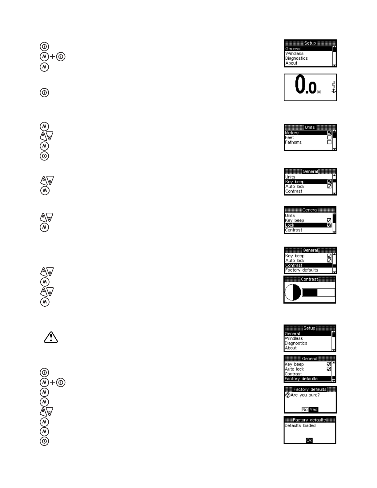
GENERAL SETUP
To Access General Set Up
Turn the AutoAnchor Off.
Hold together to display the Set up menu.
Select General.
To Exit General Set Up
Exit to the Set up menu or hold for 2 seconds to exit
to the start menu.
Set Units
Select units.
Scroll to select meters, feet or fathoms.
Save.
Return to General Menu.
Set Key Beep
Scroll to select key beep.
Save key beep on or off.
Set Lock - For safety we recommend the lock be left on.
Scroll to select lock.
Save lock on or off.
Set Contrast
Adjust contrast for best viewing at installation. This is temperature
compensated and should not require further change.
Scroll to contrast.
Select contrast.
Increase or decrease the contrast.
Save and return to General Set up.
FACTORY DEFAULTS
Resetting the Factory Defaults clears all programmed
settings.
To Reset Factory Defaults:
Turn the AutoAnchor off.
Hold together to access the Set up menu.
Select General.
Select Factory defaults
Select No/Yes.
Yes - Apply the factory reset. The AutoAnchor will turn off.
Re-enter all your Settings.
No - Return to the General menu.
Hold the On/Off button down for 2 seconds to return the
AutoAnchor to the idle state.
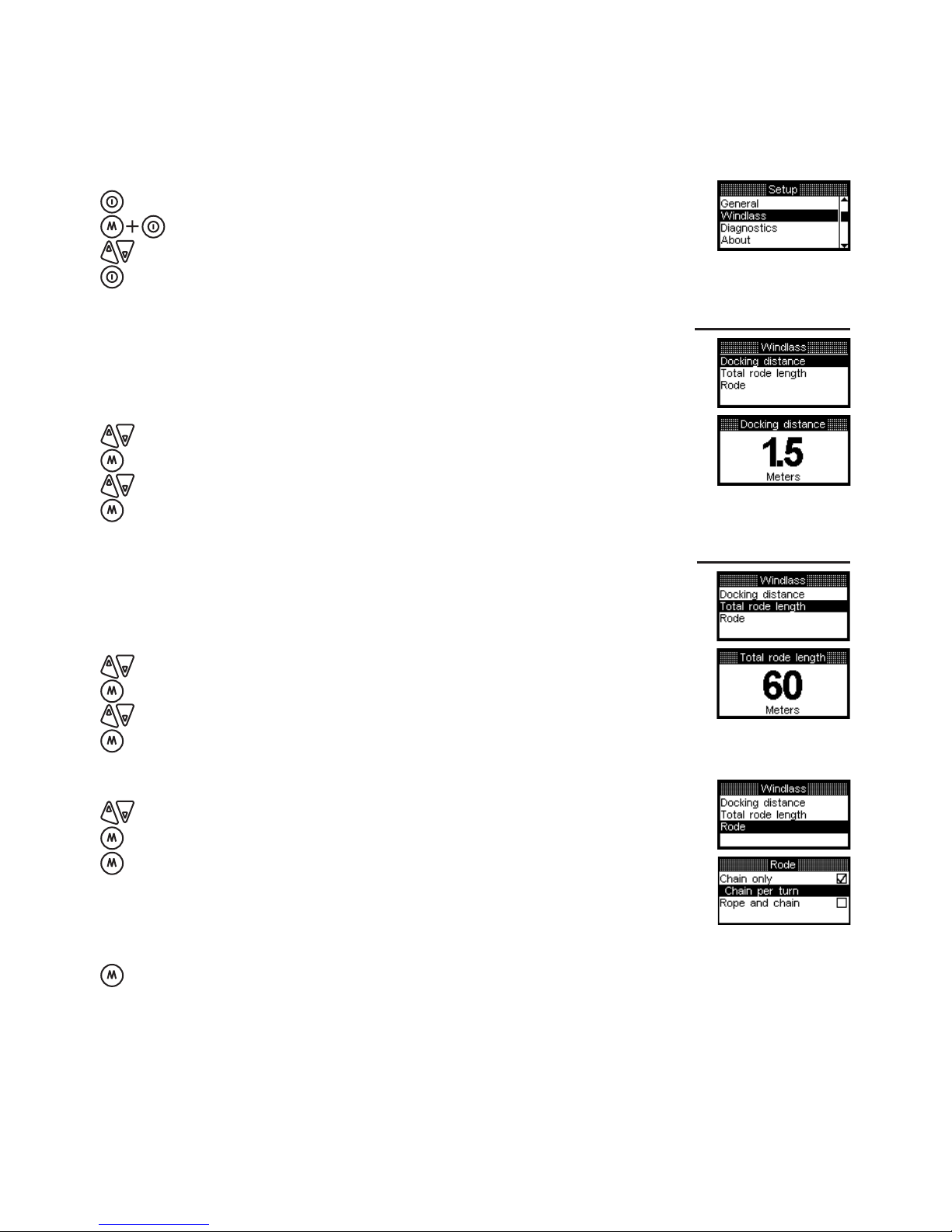
16
To Access the Windlass Set up
Turn the AutoAnchor Off.Turn the AutoAnchor Off.
Hold together to access the Set up menu.
Scroll to Windlass.
Select Windlass.Select Windlass.
WINDLASS SET UP FOR CHAIN COUNTING
For accurate chain counting you must set up the AutoAnchor with the information for your
windlass. Record the settings for future reference.
Set Docking Distance
Defaut = 1.5m or 4ft. Minimum setting = 1m or 3.3ft
This is the point during automatic retrieval when the windlass will stop.
Complete retrieval using manual operation from this point.
Scroll to Docking distance.
Select docking distance.
Increase or decrease the docking distance.
Save and return to Windlass Setup.
Setting:
Set Total Rode Length
Add total length of chain plus total length of rope
Defaut = 60m or 196 ft. Minimum setting = 10m (33 ft)
or OFF to operate as a counter only.
Scroll to Total rode length.
Select Total rode length.
Increase or decrease the value in meters or feet
Save and return to Windlass Set up.
Setting:
Set Rode
Scroll to Rode.
Select Rode.
Select Chain only or Rope and chain and follow the
instructions below to enter the settings for the rode selected.
This is the length of chain that is released during one complete turn of the chainwheel.
The information for some windlasses is listed in Appendix 1. If your windlass is not listed
follow the instructions below.
CHAIN PER TURN WHEN USING CHAIN ONLY RODE
SETTINGS FOR CHAIN ONLY RODE
Select Chain only
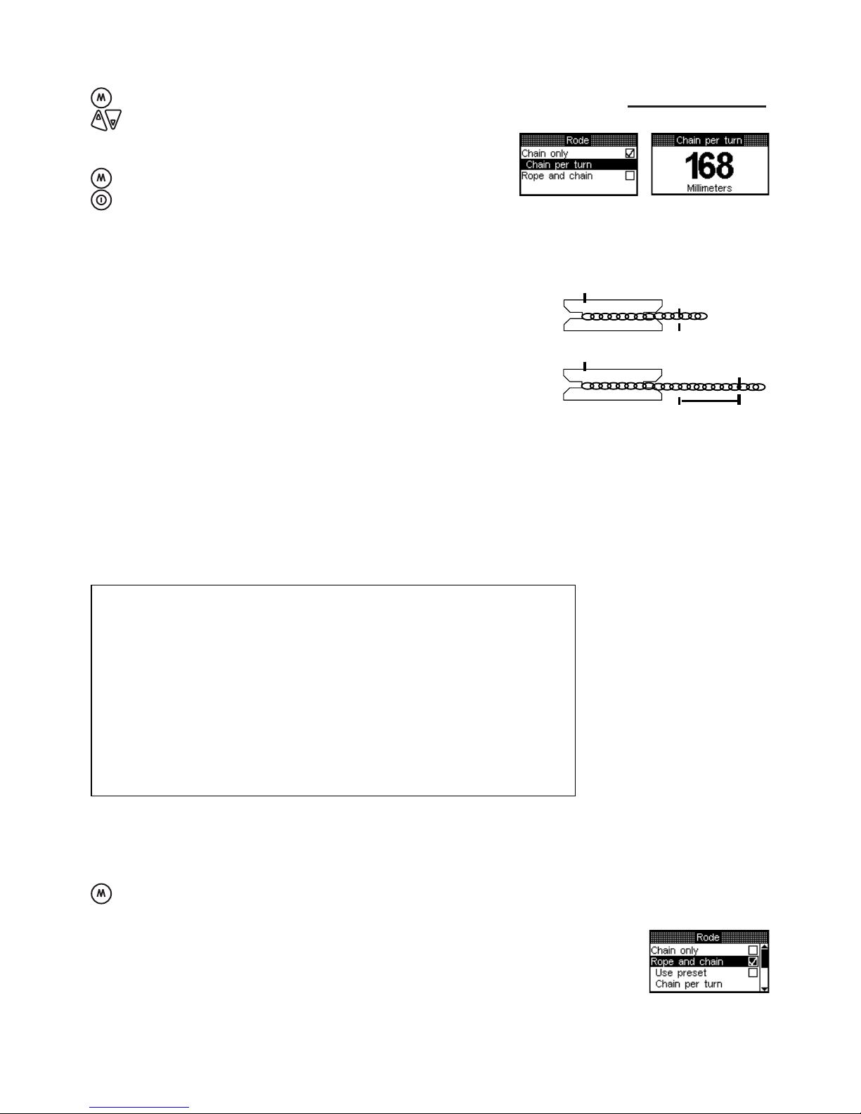
17
CALCULATING THE CHAIN PER TURN
Step 1 Use adhesive tape to place a mark on the
chainwheel.
Step 2 Use adhesive tape to place a mark on the chain
coming out of the chain wheel.
Step 3 Use adhesive tape to place a mark on the deck
below the mark on the chain.
Step 4 Carefully release the chainwheel so that it can be
turned by hand to feed the chain out.
Step 5 Using the mark on the chainwheel as a guide, turn the
chainwheel one turn, causing the chain to be
released on to the deck.
Step 6 Measure the length of chain from the mark on the
deck to the mark on the chain.
Step 7 Enter this measurement. (See below).
Chainwheel Mark
Chain Mark
Deck Mark
Distance to Measure
Select Chain per turn.
Enter the measurement. In mm or in metric inchesmm or in metric inches
(depending on units selected). See the table
below for metric inch calculations.
Save and return to Rode Set up.
Exit to Windlass Set up.
To Enter the Chain per Turn for Chain Only Rode
Setting:
SETTINGS FOR ROPE AND CHAIN RODE
Select Rope and chain
Some rope and chain windlasses have the settings already entered
in the AutoAnchor. Refer to the Preset Windlass Prole List in
Appendix 1. If your windlass is on the list select “Use preset” to
enter the Windlass prole.
If your windlass is not on the list:
You will need to enter information for the chain and rope per turn.
(See instructions on page 18).
Inches Metric Inches AutoAnchor Setting
(to 1 decimal point)
1/8 0.125 0.1
1/4 0.25 0.3
3/8 0.375 0.4
1/2 0.5 0.5
5/8 0.625 0.6
3/4 0.75 0.8
7/8 0.875 0.9
Metric Inches Conversion Table

Selecting Use Preset
Refer to the Preset Windlass Prole List list in Appendix 1.
Select Use Preset.
Select Windlass prole.
Scroll to the correct Windlass prole for your windlass.
Save and return to Windlass Set up. There are no
further settings.
Exit to Set up menu or hold for 2 seconds to return
to the start screen.
18
Setting:
This is the length of chain that is released during one complete turn of the chainwheel.
The chain per turn for some windlasses is listed in Appendix 1. If your windlass is not
listed follow the instructions on page 17 to calculate it.
CHAIN PER TURN FOR ROPE AND CHAIN RODE
Select Chain per turn.
Enter the measurement in mm or metric feetin mm or metric feet
(depending on the units selected). See the
table for metric inch calculations.
Save and return to Rode Set up.
To Enter the Chain per Turn for Rope and Chain Rode
Setting:
ROPE PER TURN FOR ROPE AND CHAIN RODE
This is the length of rope that is released during one complete turn of the chainwheel. You
need to measure the length of rope pulled through for 10 turns and divide the result by 10.
See instructions below to calculate the rope per turn.
CALCULATING THE ROPE PER TURN
Step 1 Carefully release the chainwheel so that it can be
turned by hand to feed the rode out until you have
rope.
Step 2 As you did for the chain, use adhesive tape to mark
the chainwheel, the deck and the rope. (See the
instructions for the chain per turn above).
Step 3 Using the mark on the chainwheel as a guide, pull the
rope out by hand until the chainwheel has completed
10 turns.
Step 4 Measure the length of rope pulled, divide it by 10.
Step 5 Enter this measurement (See page 19).
Chainwheel Mark Chain Mark
Deck Mark
Distance to Measure

19
Select Rope per turn.
Enter the measurement in mm or metric inchesin mm or metric inches
(depending on the units selected).
Save and return to Rode Set up. There are no further
settings.
Exit to Windlass Set up. Press twice to exit to the Set
Up menu or hold for 2 seconds to start up screen.
To Enter the Rope per Turn
Scroll to the sensor for your windlass.
Select the sensor.
If you selected an AutoAnchor sensor or the Reed baseplate
sensor there are no further settings. Exit to the Windlass set up
menu or hold for 2 seconds to return to the start screen.
Select Reed Gearbox
Scroll to Gearbox ratio
Select Gearbox ratio
Increase or decrease the Gearbox ratio
Save and exit to the Sensor set up menu
Exit to the Windlass set up menu or hold for
2 seconds to return to start screen.
Setting:
SETTING THE SENSOR
This setting appears on the Windlass set up menu. Default
setting is AutoAnchor grey sensor.
Scroll to Sensor
Select Sensor.
There are 4 sensor options: The AutoAnchor grey sensor
(supplied with the AutoAnchor kit), the AutoAnchor black
sensor, a baseplate tted reed switch sensor and a gearbox
tted reed switch sensor.
SET HIGH CURRENT SWITCH
Scroll to select High Current Switch.
Save.
Exit to Windlass Set up.
Setting:
HIGH CURRENT FOOT SWITCHES
This setting is only selected when the windlass foot switch is wired directly into the high
current side of the motor. If the High current switch is not selected the AA560 will not be
able to register the direction of the windlass. The brown and white load sensor wires must
be connected to the motor terminals for this setting. Default is off.
Other manuals for 560
2
This manual suits for next models
1
Table of contents
Other Auto Anchor Marine Equipment manuals


