AUTO-BLiP Lotus User manual

Copyright © 2012 Tractive Technology, LLC. All rights reserved. Page 2
WARNING:
Adjusting the settings of AUTO-BLiP while driving could lead to an accident and/or serious injuries. Changes should
only be
made when it is safe to do so. The primary attention of the driver should always be
on safe driving. As with
any gauge or
instrumentation system in the vehicle, any information provided by
Auto-Blip should be interacted
with as part of a normal
process of driving safely.
Auto-Blip is intended for
racing and/or off-road use only!
The mounting of AUTO-BLiP and the routing of the cable harness connecting it to the vehicle should be done
withcaution.This includes but is not limited to the following restrictions:
Do Not mount the AUTO-BLiP where it can obstruct the view of the driver
Do Not mount the AUTO-BLiP in a manner that could cause it to be propelled through the vehicle during
an accident
causing injury, such as over or near an air bag
Do Not route the cable in a manner that would interfere with the operation of the vehicle controls
INTRODUCTION:
Congratulations on your purchase of AUTO-BLiP. Please take the time to
read the entire instruction
manual
before attempting to install. DO NOT attempt the use of AUTO-BLiP until you
have completed the entire
installation process and the unit has been properly
calibrated.
WE STRONGLY RECOMMEND THAT AN EXPERIENCED TECHNICIAN INSTALL AUTO-BLiP!
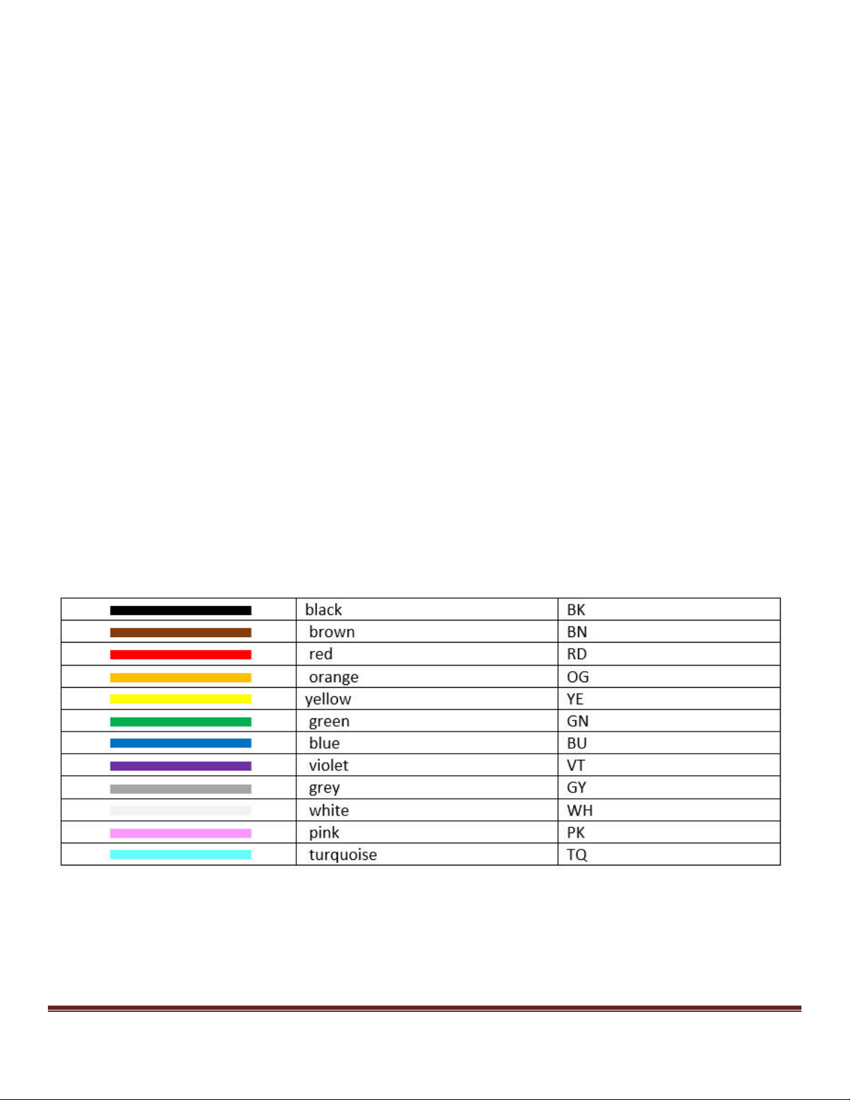
Attention: If a wire has a stripe it will be called-out by using a forward slash (/) between the main
color
and the stripe color e.g.: A black wire with purple stripe = BK/PU
Color chart with abbreviations:

Copyright © 2012 Tractive Technology, LLC. All rights reserved. Page 3
Signal Description
AUTO-BLiP Harness color code
Lotus wiring connections
Ground
Black
Clutch sensor
Yellow
Figure 2
12v
White
Figure 5
Brake sensor
Blue
Figure 3
Accelerator Pedal
Position Sensor 1 (APPS)
Red
Figure 4
Accelerator Pedal
Position Sensor 2 (APPS)
Green
Figure 4
GUIDE CHART:
Tools
(not all may be necessary depending on type of instal):
Needle nose pliers
Light (Forehead mounted recommended)
Wire cutters / strippers - optional
Digital Multimeter (DMM) - optional
X-Acto knife or equivalent - optional
Connections
(IGNITION MUST BE OFF DURING INSTALLATION!):
Note:
When performing this installation, make
sure the wire harness is securely routed away from any
moving parts! If posible, secure the Auto-Blip harness to the car manufacturer's
harness for added safety.
Note:
Soldering the Auto-Blip harness wires (6) to the respective car wires provides for the
best
results.
However, due to the challenge of working under the dash, this should only be done by a
professional.
Auto-Blip provides alternative hardware to achieve good results. This hardware must be
carefully installed to
achieve the desired results.
When connecting
the wire harness
connectors
to the corresponding T-tap
connectors, make
sure
to
slide the connector
completely
in
until it reaches the stop.
Note:
This vehicle may be equipped with two switches at the clutch pedal. The Cruise Control Disable switch
is usually mounted higher up under the dashboard. The Safety Interlock switch is usually down lower on the
pedal where it is visible. For this installation, you will only be working with the clutch Safety Interlock switch.
Figure 2 or alternate install Figure 5

Copyright © 2012 Tractive Technology, LLC. All rights reserved. Page 4
1. Using a pair of pliers, securely attach supplied wire t-taps to all the specified wires shown in Figures 2, 3, 4
and 5.
2. Connect the AUTO-BLiP’s spade connectors to each of the specified t-tap as shown in Figures 2, 3, 4 and 5.
Lotus wire color coding
Connections
(continued):
ATTENTION:
AUTO-BLiP
will not work until you complete
the CALIBRATING UNIT process on page 10
Copyright © 2012 Tractive Technology, LLC. All rights reserved. Page 5
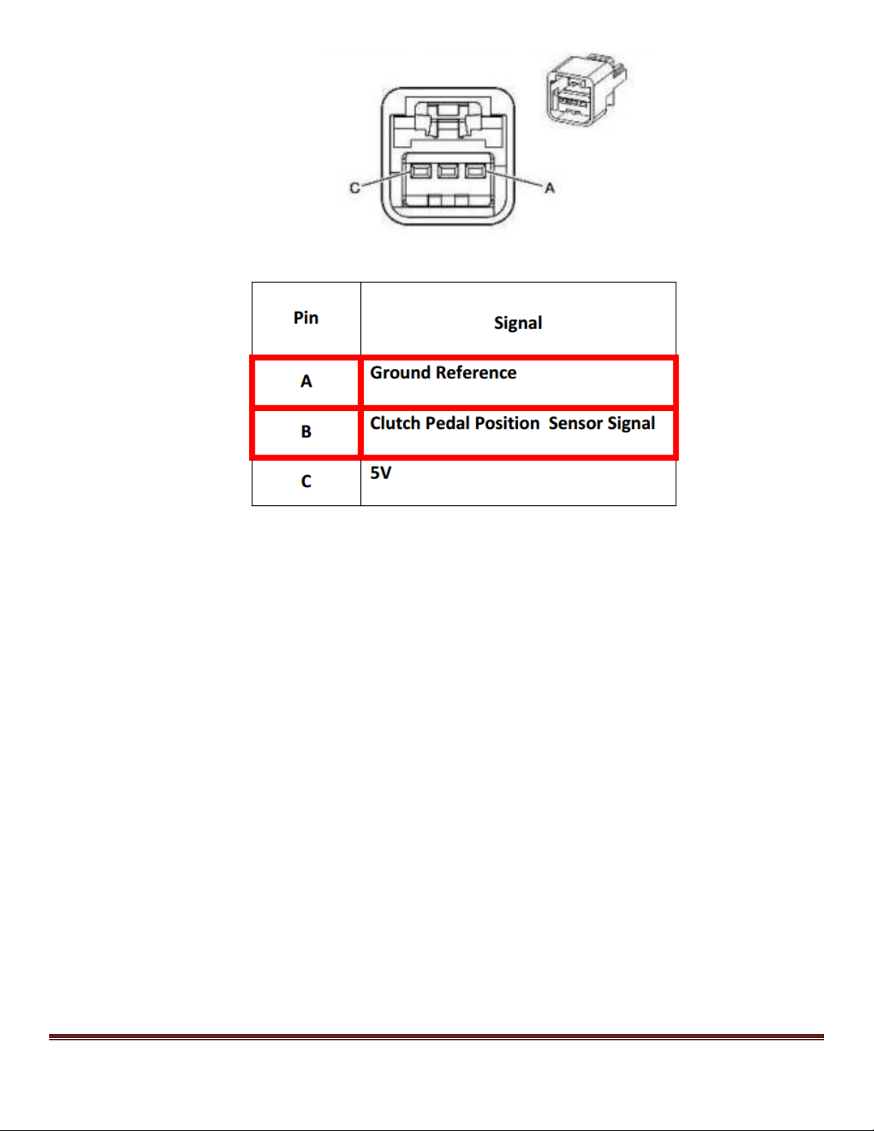
Figure 1 (Clutch pedal position sensor connector)
Copyright © 2012 Tractive Technology, LLC. All rights reserved. Page 6
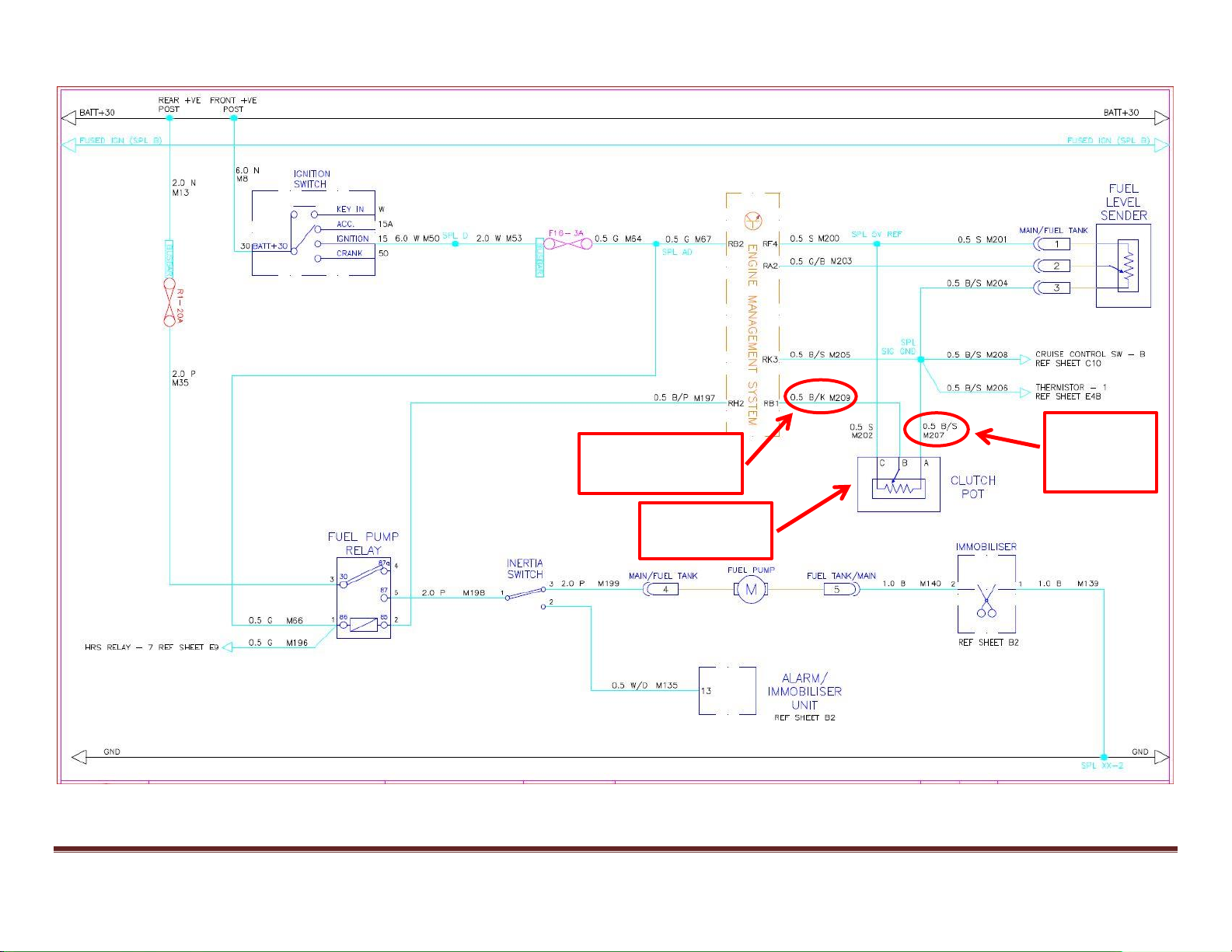
Figure 2 (Clutch pedal sensor wiring diagram)
Clutch pedal
position sensor
AUTO-BLiP
BLACK wire
connection
AUTO-BLiP YELLOW
wire connection

Copyright © 2012 Tractive Technology, LLC. All rights reserved. Page 7
Figure 3 (Brake pedal sensor wiring diagram)
Brake pedal
switch
AUTO-BLiP BLUE
wire connection

Copyright © 2012 Tractive Technology, LLC. All rights reserved. Page 8
Figure 4 (Accelerator pedal sensor wiring diagram)
Accelerator pedal
position sensor
AUTO-BLiP RED
wire connection
AUTO-BLiP GREEN
wire connection
Copyright © 2012 Tractive Technology, LLC. All rights reserved. Page 9
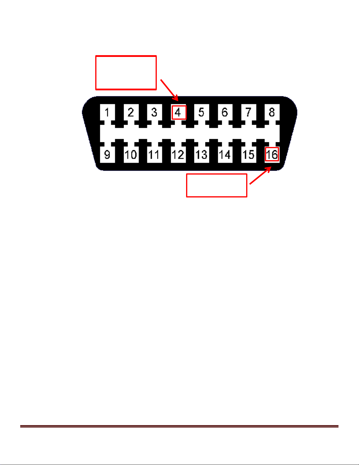
AUTO-BLiP WHITE
wire connection
ALTERNATE
AUTO-BLiP BLACK
wire connection
Figure 5 (OBD 2 Connector 12v
supply
& alternate placement for Ground)
Copyright © 2012 Tractive Technology, LLC. All rights reserved. Page 10
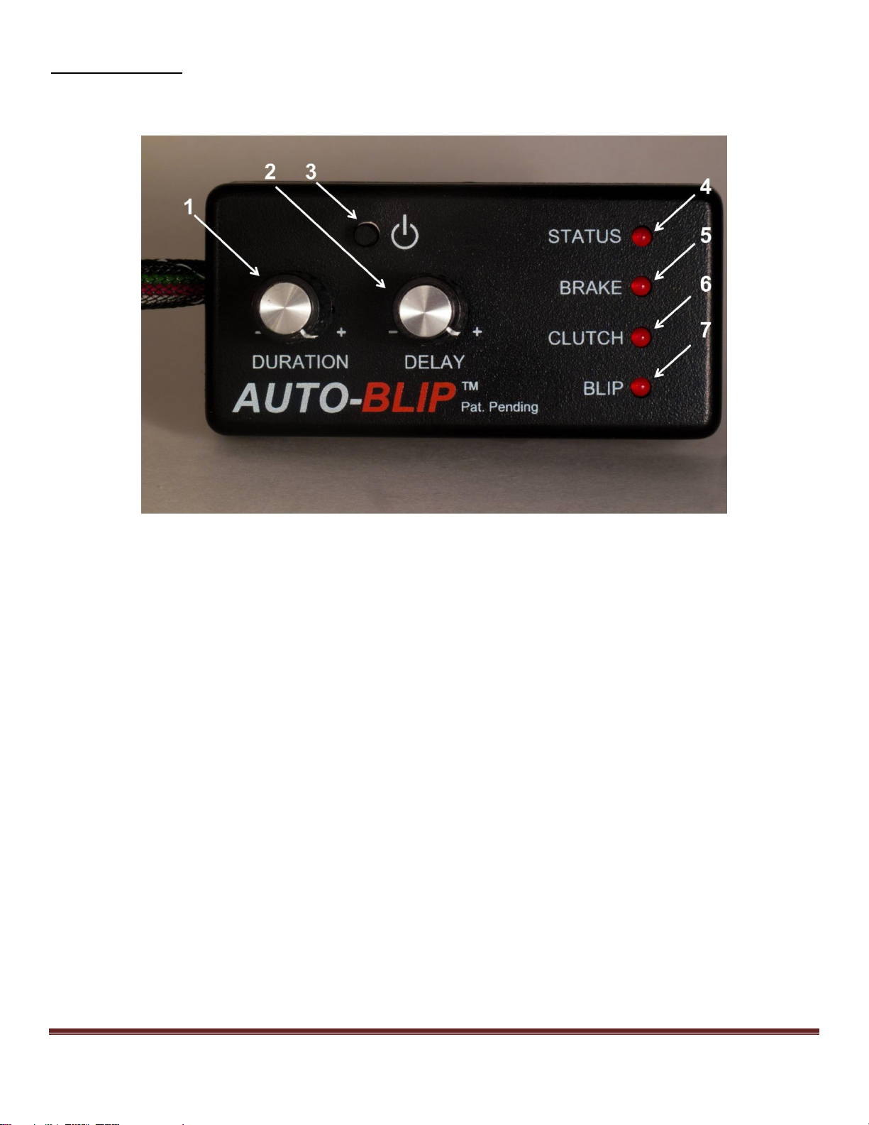
HOW IT WORKS
1. The “DURATION” dial sets the desirable RPM blip level by opening the throttle. Turn dial clockwise to increase
RPM blip level.
2. The “DELAY” dial allows for the insertion of a constant time delay from the time a downshift event is sensed to
when the unit blips the throttle. Turn dial clockwise to increase delay. Range from 0 to 0.5 seconds.
3. The ON/OFF button will toggle between the ON and OFF mode. The unit will default to the ON state upon power
up.
Note: This button is also use to enable the calibration mode. Refer to the Calibrating Unit section below for
more details.
4. The “STATUS” LED turns on when the unit is ON.
5. The “BRAKE” LED turns on when the brake pedal is pressed.
6. The “CLUTCH” LED turns on when the clutch pedal is pressed.
7. The “BLIP” LED turns on when a throttle blip event occurs.
Note: The AUTO-BLIP will automatically turn OFF after 6 hours of inactivity. It will remain OFF until the ON/OFF
button is pressed or power to the unit is removed and re-applied.
The AUTO-BLiP monitors your automobile’s accelerator pedal, brake pedal, and clutch pedal, blipping the
throttle only when the clutch pedal is being depressed while simultaneously braking.

Copyright © 2012 Tractive Technology, LLC. All rights reserved. Page 11
CALIBRATING UNIT
In order for your AUTO-BLiP unit to function properly, you must first perform the calibration sequence outlined in
this section!!!
1. Turn on ignition, but do not start engine. AUTO-BLiP “STATUS”LED light will light up. If not, turn ignition off and
verify the power supply and ground connectors are fully seated.
2. Set the “DURATION” dial completely counter clockwise (-) and the “DELAY” dial to the 12 o’clock position.
3. To enter the calibration mode, press and hold down the ON/OFF button (about 10 seconds) until the “STATUS”
LED continuously blinks (1) time followed by a short pause.
4. Press and hold the accelerator pedal approximately %60. While holding the accelerator pedal open, press and
release the ON/OFF button once, continue to hold the accelerator pedal down. This step records your vehicle’s
full open throttle pedal position.
5. At this point the “STATUS”LED light will blink (2) times followed by a short pause. Completely release the
accelerator pedal. With the accelerator pedal completely released, press and release the ON/OFF button once.
This step records your vehicle’s close throttle pedal position.
6. At this point the “STATUS”LED light will blink (3) times followed by a short pause. Press the brake pedal. With
the brake pedal completely pressed, press and release the ON/OFF button once, continue to hold the brake
pedal down. This step records your vehicle’s brake pedal pressed position.
7. At this point the “STATUS”LED light will blink (4) times followed by a short pause. Completely release the brake
pedal. With the brake pedal completely released, press and release the ON/OFF button once. This step records
your vehicle’s brake pedal released position.
8. At this point the “STATUS” LED light will blink (5) times followed by a short pause. Press the clutch pedal to the
position where you want the AUTO-BLiP to activate. With the clutch pedal pressed, press and release the
ON/OFF button once, continue to hold the clutch pedal down. This step records your vehicle’s clutch pedal
pressed position. (See Note 1)
9. At this point the “STATUS” LED light will blink (6) times followed by a short pause. Release the clutch pedal
approximately ½” to 1” from the pressed position in step 8. With the clutch pedal released approximately ½” to
1”, press and release the ON/OFF button once. This step records your vehicle’s clutch pedal released position.
10. This completes calibration of the AUTO-BLiP unit!
Note 1: This vehicle is equipped with an analog position sensor. This allows the user to set where in the pedal
travel position the AUTO-BLiP blips the throttle.
Note: When properly calibrated, the “BRAKE” and “CLUTCH” LEDs will turn on when the corresponding pedal is
pressed.
The AUTO-BLiP features a diagnostic function that will warn the user when the AUTO-BLiP’s calibration routine
fails to properly recognize the accelerator pedal position sensor (APPS), BRAKE, and/or CLUTCH signals. Failures
related to the BRAKE and/or CLUTCH will prevent the unit from exiting the calibration sequence. This is done to
prevent AUTO-BLiP from blipping the throttle at the incorrect time. When a failure is detected the AUTO-BLiP will
continuously blink the “BRAKE”, “CLUTCH”, and/or “BLIP” LEDs, signaling a failure during calibration of the
respective signals. Press and release the ON/OFF button once to re-start the calibration sequence from the
beginning.

Copyright © 2012 Tractive Technology, LLC. All rights reserved. Page 12
TECH SUPPORT
In the event of a malfunction, please check the following:
1. Turn off ignition then verify all connectors are fully seated.
2. Make sure the unit is properly powered. When unit is properly powered the “STATUS” LED will remain
continuously lid.
3. Be sure the unit has been calibrated,
as outlined in the calibration section, according to your vehicle’s model and
year.
4. Check harness for cuts, scrapes or abrasions.
5. Technical support: call (713)289-4015 (Mon-Fri from 9A-3P CST); email [email protected]

Copyright © 2012 Tractive Technology, LLC. All rights reserved. Page 13
AUTO-BLiP LIMITED WARRANTY
Tractive Technology, LLC warrants this product against defects in material and workmanship for the period of 90 days.
The warranty period begins with the date of original retail purchase.
This limited warranty is made only to the original end user purchaser ("you") of the product and does not extend to any
subsequent purchasers or owners of the product. The "original end user" is the first user to put the product into service
in any fashion. It is your responsibility to establish the warranty period by verifying the original purchase date.
If you discover a defect, Tractive Technology, LLC will, at its option, repair or replace this product with a new or
reconditioned product at no charge to you, provided you return it during the warranty period, with transportation
charges prepaid, to Tractive Technology, LLC. (You can obtain additional information by contacting Tractive Technology,
LLC at the address printed on the card). Please attach your name, address, telephone number, and a copy of the bill of
sale as proof of date of original retail purchase, as well as a detailed description of the problem for which service is
requested. Prior to returning the product, you must obtain from Tractive Technology, LLC a Return Merchandise
Authorization Number (RMA#). You are responsible for packing the product to be returned. If the repairs are covered by
the Limited Warranty and if the product was properly shipped to Tractive Technology, LLC, Tractive Technology, LLC will
pay the return shipping charges. This warranty applies only to AUTO-BLiP product manufactured by Tractive Technology,
LLC that can be identified by the "AUTO-BLiP" trademark, trade name, or logo affixed to them. This warranty does not
cover damage resulting from an accident, misuse, abuse, or neglect and/or damage during any type of transportation
resulting from improper packaging; damage to any product which has been altered in any fashion, including the
alteration or removal of any Tractive Technology, LLC serial number; damage resulting from causes other than product
defects, including and not by way of limitation, lack of technical skill, competence, or experience of the user, and/or
failure to use the product in accordance with the instructions provided in the User's Manual; and service performance
by an unauthorized person or entity. Any implied warranties including fitness for use and merchantability are limited in
during to the period of the expressed warranty set forth above. The remedies provided under this warranty are exclusive
and in lieu of all others. Tractive Technology, LLC hereby expressly disclaims liability and shall not be responsible for
incidental, consequential and contingent damages or any kind of nature, including, without limitation: damages to
persons or property, whether a claim for such damages is based upon warranty, contract, tort or otherwise; damages to
persons or property, whether a claim for such damages is based upon warranty, contract, tort or otherwise; damages
due to or arising out of the loss of date; or lost of profits. Tractive Technology, LLC shall not be responsible for any
damages caused by the presence of error or omission in any of its manuals, instructions or related materials.
For warranty claims contact
Latitude 305, LLC d/b/a Auto-Blip at:
(713)289-4015
or email:
Table of contents
Other AUTO-BLiP Automobile Accessories manuals


