RaceChip XLR User manual
User Manual
PLEASE
READ BEFORE
STARTING
INSTALLATION!
Download
the new
RaceChip+ app
bit.ly/RCplus-iOS
bit.ly/RCplus-android
MB C-Class (W/S/C204) C 220 CDI

2
1 Scope of delivery.............................................................................................................................................3
2 Installation .......................................................................................................................................................4
3 Trouble Shooting ..........................................................................................................................................11
4 Contact ...........................................................................................................................................................15
Contents
Overview and explanation of symbols
Warnings and important information – please read!
General information on installation and use
Tips to assist installation and use
User Manual
PLEASE
READ BEFORE
STARTING
INSTALLATION!
Download
the new
RaceChip+ app
bit.ly/RCplus-iOS
bit.ly/RCplus-android
3
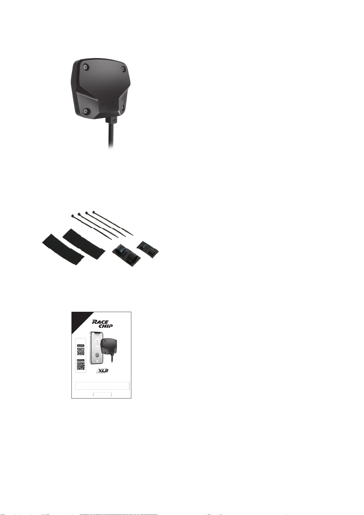
1 Scope of delivery
Brainbox
Fasteners
User Manual
Speci cally modi ed to suit your car.
Material to x the Brainbox in place.
Installation and operation.

4
2 Installation
Step 1 of 5 – Preparation
Open the driver’s door as far as possible.
Remove any mats and move the driver’s seat all the way back.
Switch the ignition off, remove the key.
Ensure the footwell is properly illuminated with an inspection lamp.
Wait about 10 minutes before starting Step 2, as all current consumers must have
switched themselves off.
• For cars with “Keyless Go”: after locking the car, place the key out of signal range
(about 10 m from the car).
• If an alarm system is tted: disable the alarm before starting installation.
1
2
3
4
5
5
2 Installation
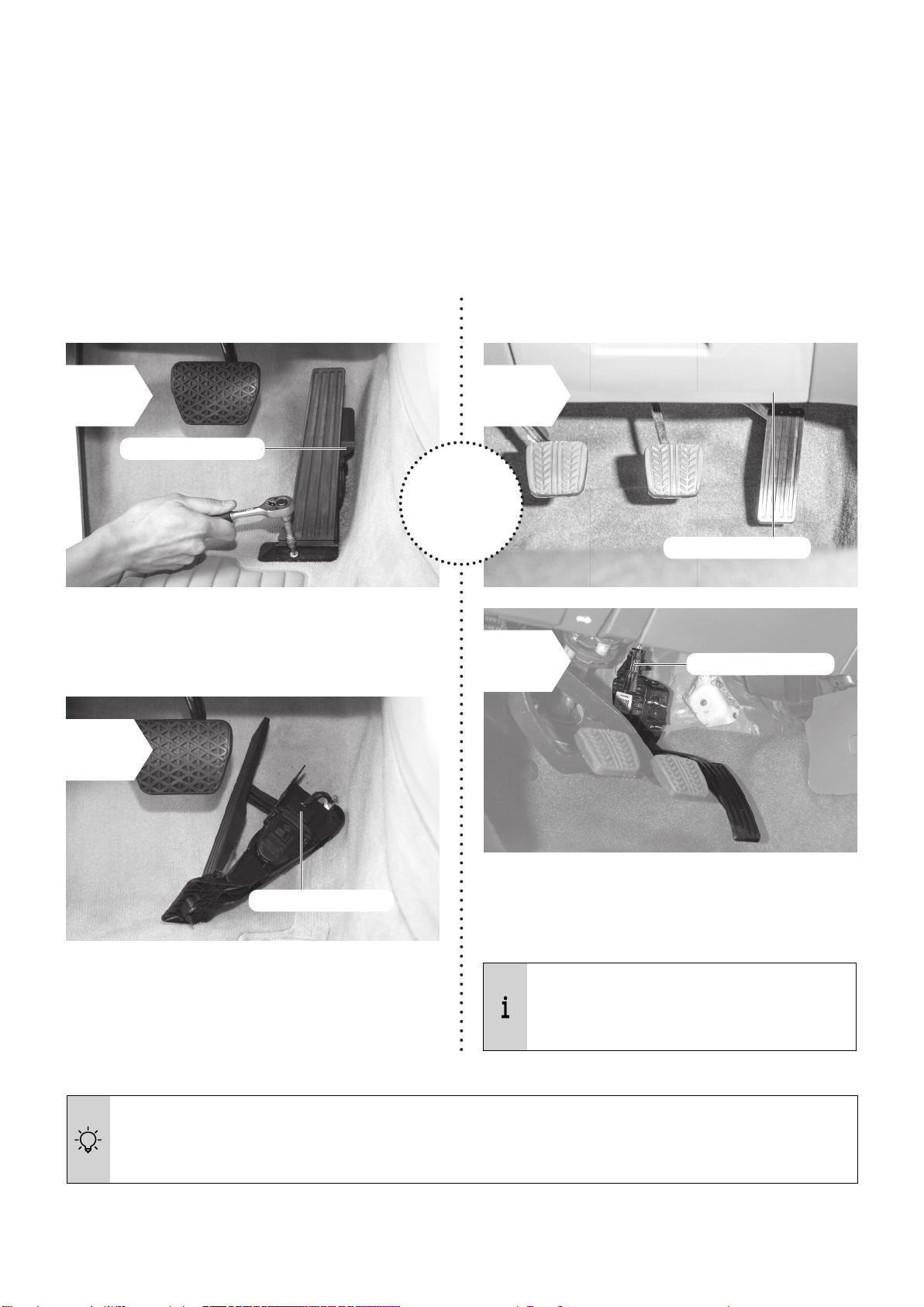
Step 2 of 5 – Disconnect throttle pedal sensor
There are two types of throttle pedal: fl oor-mounted or hanging. We’ll explain how to disconnect
the throttle pedal sensor for both types.
A. Floor-mounted throttle pedal B. Hanging throttle pedal
If you need assistance in detaching the throttle pedal sensor connector: see the
additional instructions “Detaching the connector correctly”.
B1
You might have to remove part of the
trim to get to the connector.
OR
Throttle pedal sensor
• The throttle pedal sensor is on the right-
hand side of the throttle pedal. Carefully
pull off the connector of the throttle pedal
sensor.
A2
Throttle pedal sensor
A1
Throttle pedal sensor
Throttle pedal sensor
B2
• Disassemble the throttle pedal with the
appropriate tools.
• The throttle pedal sensor is at the top of
the throttle pedal. Carefully pull off the
connector of the throttle pedal sensor.
B
A
A B
6
2 Installation
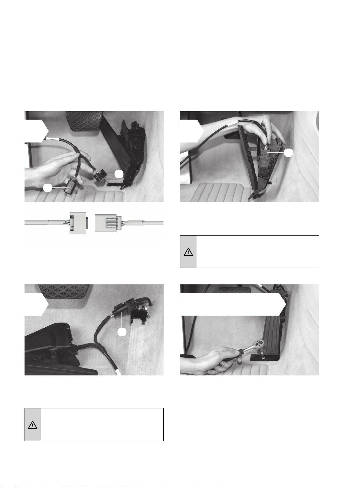
Step 3 of 5 – Connect the Brainbox
The car used to illustrate these instructions is for demonstration purposes only. The basic proce-
dure is exactly the same even if the details of your car look different.
• The cable leading from the Brainbox has
two connectors (marked Aand B).
• Attach connector A from the Brainbox to
the gas pedal sensor.
• Now attach connector B to the connector
you pulled off the gas pedal.
A sharp click indicates that the
retaining clip has engaged fully.
A sharp click indicates that the
retaining clip has engaged fully.
1 2
3 4 Only if the throttle pedal
has been disassembled:
• Re-assemble the throttle pedal.
• Make sure the cable is not trapped and
does not interfere with the pedals.
• Ensure the throttle pedal is rmly xed in
the proper position.
A
B

7
2 Installation
Step 4 of 5 – Fix the Brainbox
We recommend two places for fi xing the Brainbox (although there may be other possibilities):
A. On the left of the footwell next
to the footrest.
• Fix one part of the hook-and-eye fastener
tape to the bottom of the Brainbox.
• Fix the other part of the fastener tape to
the site indicated in the footwell. Make sure
the site is free of dust and grease rst.
• Now press the two halves of the fastener
together (see picture for Brainbox position).
• First test carefully to see if the Brainbox will
t under the trim.
• If the Brainbox ts, slide it carefully under
the trim into the position shown.
B. Under the trim on the centre tunnel
Secure the Brainbox and its wiring so that they do not interfere with the pedals and
cannot slide into the footwell.
1x hook-and-
loop fastener
hook-and-loop
fastener
OR
Brainbox
A1 B1
Brainbox

8
2 Installation
A. On the left of the footwell next
to the footrest
B. Under the trim on the centre tunnel
• Use the cable clips and/or cable ties to secure the cable between the Brainbox and the
gaspedal, ensuring that nothing interferes with the pedals.
2x cable clips 4x cable ties
cable clips
A2
cable clips
B2

9
2 Installation
Step 5 of 5 – Pair RaceChip XLR with your smartphone
Download the free RaceChip+ app.
Open the RaceChip+ app.
Switch on the ignition of your car. Do not start the engine.
With opening the RaceChip+ app for the rst time, the
installation dialogue for chip tuning by RaceChip is shown.
Touch ADD PRODUCT and follow the instructions given by
your smartphone.
According to your operating system (Android and Apple), the steps for connecting the RaceChip
and your smartphone may vary. Please nd the most important steps below. In general, you
should follow the instructions given by your smartphone for the connection.
Activate the Bluetooth function of your smartphone.
• The connection between the RaceChip and your smartphone is set up in the last step
of the installation process.
• The RaceChip is fully functional even if there is no connection to a smartphone
running the RaceChip+ app.
• The RaceChip XLR is now in the factory setting SPORT after rst pairing.
1
2
4
5
3

7
10
2 Installation
6You can enter the serial number by hand (touch MANUALLY) or with the barcode scanner
of the camera (touch
You can enter the serial number by hand (touch
). Con rm the entry with NEXT.
As soon as the connection is set up, the installation is completed.
Having trouble with connecting RaceChip XLR and your phone’s Bluetooth?
Follow these steps one by one until the pairing is complete:
1. Check that the car’s ignition is switched on.
2. Check that the Bluetooth function on your smartphone is fully activated.
3. Deactivate and then re-activate the Bluetooth connection. Check if RaceChip
and your phone will pair now.
4. Re-start the RaceChip+ app.
5. Go to your smartphone’s settings and view all discoverable Bluetooth devices. If
your RaceChip (RC XLR) is not visible, please contact our customer service.
The 13-digit serial number is located on the
cover of your user manual (paper version).
Alternative you can also nd the serial number
on the housing of the Brainbox. The Bluetooth
PIN consists of the last 6 digits of the serial
number.
Serial number
Bluetooth-PIN
Example:
Other manuals for XLR
1
Other RaceChip Automobile Accessories manuals


