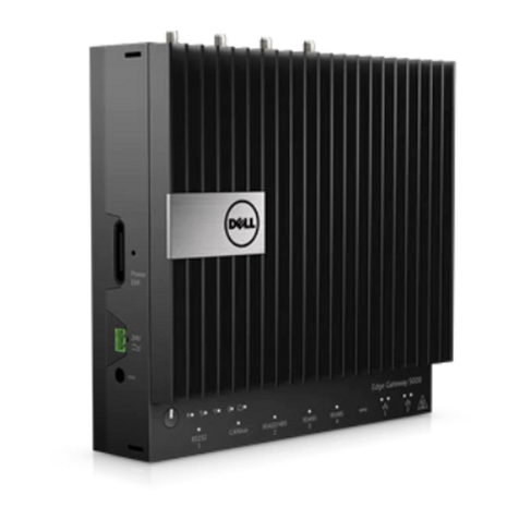
Autocall A2975-9234 User manual

IP Gateway External Box Installation Guide
579-1249AC Rev. E
*05791249ACE*

This page is intentionally blank

Contents 1 Cautions, warnings, and regulatory information...................................................................................... 3
2 Overview.........................................................................................................................................................4
2.1 Related documentation....................................................................................................................................................................... 4
2.2 Dimensions........................................................................................................................................................................................... 5
2.3 Positioning the external box............................................................................................................................................................... 5
3 Mounting the external box...........................................................................................................................6
3.1 Close-nippled mounting...................................................................................................................................................................... 6
3.2 Remote mounting.................................................................................................................................................................................6
3.3 Remote and close-nippled mounting guidelines..............................................................................................................................6
3.4 Mounting the IP Gateway External Box............................................................................................................................................. 7
3.5 Mounting the IP Gateway in the external box...................................................................................................................................8

This page is intentionally blank

IP Gateway External Box Installation Guide
1 Cautions, warnings, and regulatory information
READ AND SAVE THESE INSTRUCTIONS Follow the instructions in this installation manual. These instructions must be followed to avoid
damage to this product and associated equipment. Product operation and reliability depend upon proper installation.
DO NOT INSTALL ANY AUTOCALL™ PRODUCT THAT APPEARS DAMAGED Upon unpacking your Autocall product, inspect
the contents of the carton for shipping damage. If damage is apparent, immediately file a claim with the carrier and notify an
authorized Autocall product supplier.
ELECTRICAL HAZARD Disconnect electrical field power when making any internal adjustments or repairs. All repairs should
be performed by a representative or an authorized agent of your local Autocall product supplier.
STATIC HAZARD Static electricity can damage components. Handle as follows:
• Ground yourself before opening or installing components.
• Prior to installation, keep components wrapped in anti-static material at all times.
FCC RULES AND REGULATIONS – PART 15. This equipment has been tested and found to comply with the limits for a Class A digital
device, pursuant to Part 15 of the FCC Rules. These limits are designed to provide reasonable protection against harmful interference
when the equipment is operated in a commercial environment. This equipment generates, uses, and can radiate radio frequency energy
and, if not installed and used in accordance with the instruction manual, may cause harmful interference to radio communications.
Operation of this equipment in a residential area is likely to cause harmful interference in which case the user will be required to correct
the interference at his own expense.
page 3 579-1249AC Rev. E

2 Overview
This guide describes how to install the IP Gateway External Box. The external box is used for either remote or close-nippled installations of
the IP Gateway.
Note: Refer to the IP Communicator / Connected Services Gateway Module Installation Guide 579-1296AC and 2050 / 2250 Panels IP
Communicator / Connected Services Gateway Module Installation Guide 579-1463AC for more information.
Figure 1: IP Gateway External Box
2.1 Related documentation
You can consult the following additional documentation:
• IP Communicator / Connected Services Gateway Module Installation Guide 579-1296AC
• 2050/ 2250 Panels IP Communicator / Connected Services Gateway Module Installation Guide 579-1463AC
• IP Gateway Cellular Module Installation Guide 579-1248AC
• Power over Ethernet Switch Card Installation Guide 579-1250AC
page 4 579-1249AC Rev. E
IP Gateway External Box Installation Guide

2.2 Dimensions
The IP Gateway External Box measures H 6.1 in x W 9.4 in. x D 2.3 in. (H 15.5 cm x W 23.9 cm x D 5.8 cm ). It has a separate cover which
slides over the box and is secured by four #6-32 screws supplied. You must mount the box using four #10-32 screws which are not
supplied.
Figure 2: External box dimensions
2.3 Positioning the external box
You can mount the external box on either the left or right side of the FACU.
Figure 3: External box orientation
page 5 579-1249AC Rev. E
IP Gateway External Box Installation Guide

3 Mounting the external box
You can mount the IP Gateway in an external box for either remote or close-nippled installations.
Reasons for installing the IP Gateway in the external box are as follows:
• Inadequate space for mounting an antenna on the FACU due to conduit interference.
• Inadequate space for mounting the IP Gateway inside the FACU.
• Poor cellular signal strength where the FACU is located.
3.1 Close-nippled mounting
Locate the IP Gateway at a maximum of 20 ft (6.096 m) from the 4007ES / 4010ES / 4100ES FACU and maximum of 6 ft (1.82 m) from the
A050 / A250 FACU when the external box is close-nippled. Run all wiring in metal conduit. You can connect the IP Gateway to power the
CPU card, Ethernet port, Serial port and front panel service port in the same way as internal mount installations, however, you require
alternate cabling. The external box kit includes an 8 ft (2.438 m) cable to connect power to the IP Gateway. If you require a longer cable,
order a 20 ft (6.096 m) cable. The kit does not include Ethernet cable. You must locally source cable for the length that you require. Use
category 5 Ethernet cable, or better, in the installation. Coil-up and tie-off excess cable in the FACU. Do not coil-up and tie-off cable in the
external box.
For A050 and A250 panels, order 734-383, 6 ft communication cable separately. The supplied 8 ft power cable is used for close-nippled
connection up to 6 ft.
3.2 Remote mounting
Locate the IP Gateway at a maximum of 328 ft (100 m) from the FACU in an area with stronger cellular signal. The IP Gateway connects to
the FACU in remote installations through the Simple Power over Ethernet Switch (SPES) module. Install the SPES module internally in the
FACU. Refer to Power over Ethernet Switch Card Installation Guide 579-1250AC for information on installing the SPES module, and wiring to
the IP Gateway remotely.
Note: Not applicable for A050 and A250 panels.
3.3 Remote and close-nippled mounting guidelines
Consult the following guidelines before mounting the external box:
• Do not mount the IP Gateway Module before external box or conduit installation.
• You must use 3/4 in. (1.9 cm) conduit to enable the Ethernet connectors and core-4 connector to feed through the conduit easily.
Note: If you use smaller conduit, you may need to remove and re-pin the connectors.
• Surface-mount the external box.
Refer to Table 1 for IP Gateway External Box options:
Table 1: IP Gateway External box options
PID Color
A2975-9234 Red
page 6 579-1249AC Rev. E
IP Gateway External Box Installation Guide

3.4 Mounting the IP Gateway External Box
To mount the IP Gateway External Box, do the following:
1. Locate the space to mount the external box, and take steps to ensure that the location aligns with routing for planned conduit.
Note: Mount the box high enough to ensure that any antenna you may install is not blocked by temporary structures.
2. Using the mounting holes as a template, mark the location for the drill holes on the wall.
3. Remove the conduit entry knockouts that you are using for the installation.
Note: The external box also includes knockouts to install an antenna or antenna extension for the IP Gateway. Refer to the IP Gateway
GSM Cellular Module Installation Guide 579-1248AC.
4. Drill holes in the wall to accommodate four #10-32 screws.
5. Insert the mounting screws into the top two holes leaving a 1/8 in. (3.175 mm) gap between the screw head and the wall.
6. Place the top teardrop holes in the back box over the screws and tighten to hang the box.
7. Insert the remaining screws through the bottom mounting holes in the box and tighten.
8. Connect the conduit.
Figure 4: Mounting the external box
Callout Description
A #10-32 screws
B Conduit knockout
C Antenna knockout
D Teardrop holes
E Antenna knockout
page 7 579-1249AC Rev. E
IP Gateway External Box Installation Guide

579-1249AC Rev. E
© 2023 Johnson Controls. All rights reserved. All specifications and other information shown were current as of document revision and are subject
to change without notice. Additional listings may be applicable, contact your local Autocall product supplier for the latest status. Listings and
approvals under Tyco Fire & Security GmbH, and the product names listed in this material are marks or registered marks. Unauthorized use is strictly
prohibited. NFPA 72 and National Fire Alarm Code are registered trademarks of the National Fire Protection Association (NFPA).
3.5 Mounting the IP Gateway in the external box
To mount the IP Gateway in the IP Gateway External Box, do the following:
1. Align the IP Gateway with the four holes on the back of the box.
2. Attach the IP Gateway using the four #6-32 x 5/8 in. screws included with the IP Gateway.
Note: The four #4-40 screws that are with the IP Gateway PCA, only use them to mount the PCA inside the Fire Panel enclosure.
3. Connect the IP Gateway as required by the installation type.
- For close-nippled installations, refer to IP Communicator / Connected Services Gateway Module Installation Guide 579-1296AC and
2050 / 2250 Panels IP Communicator / Connected Services Gateway Module Installation Guide 579-1463AC.
- For remote installation, refer to Power over Ethernet Switch card Installation Guide 579-1250AC.
4. Attach the cover of the box using the four screws provided. Ensure that the appliqué is in the correct orientation.
Figure 5: Mounting the IP Gateway
Table of contents
