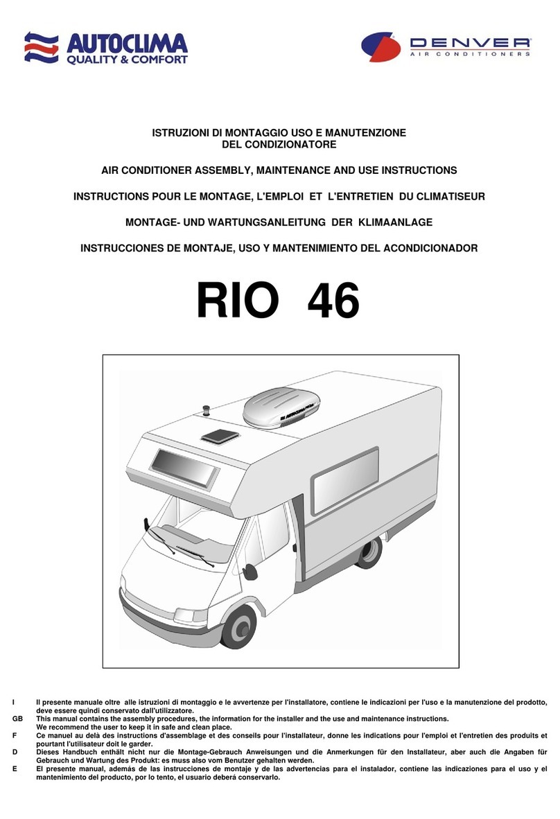
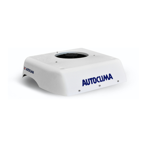
Autoclima Fresco 3000 ALASKA User guide

ISTRUZIONI DI MONTAGGIO USO E MANUTENZIONE DEL CONDIZIONATORE
AIR CONDITIONER ASSEMBLY, MAINTENANCE AND USE INSTRUCTIONS
INSTRUCTIONS POUR LE MONTAGE, L'EMPLOI ET L'ENTRETIEN DU CLIMATISEUR
MONTAGE- UND WARTUNGSANLEITUNG DER KLIMAANLAGE
INSTRUCCIONES DE MONTAJE, USO Y MANTENIMIENTO DEL ACONDICIONADOR
ALASKA
COD. 12121680 (12V)
COD. 12121907 (24V)

1
/
26
ALASKA
NOTE / NOTES / NOTAS
I Le indicazioni che si riferiscono alla DESTRA ed alla SINISTRA, sono relative al conducente del mezzo rivolto in direzione
del senso di marcia.
EN
e
The indications which refer to the RIGHT and to the LEFT concern the driver of the vehicle on the drive way.
F Les indications qui se réferent à DROITE et GAUCHE, sont considérées par rapport au conducteur du véhicule dirigé dans
le sens de la marche, par conséquence.
D
e
Die Anzeigen RECHTS und LINKS sind auf den Fahrer in Fahrtrichtung bezogen.
E Las indicaciones que hacen referencia a la DERECHA o la IZQUIERDA, se refieren al conductor del vehículo en el sentido
de la marcha.
SOMMARIO PAGINA CONTENTS PAGE
DIMENSIONI 2 DIMENSIONS 2
CARATTERISTICHE TECNICHE 5 NOMINAL TECHNICAL DATA 5
POSIZIONE COMPONENTI 6 COMPONENTS DISPOSITION 6
CIRCUITO FRIGORIGENO 7 COOLING SYSTEM 7
COLLEGAMENTI ELETTRICI 12V - 24V 8 - 9 ELECTRICAL CONNECTIONS 12V - 24V 8 - 9
SCHEMI ELETTRICI 12V - 24V 10 - 11 WIRING DIAGRAMS 12V - 24V 10 - 11
MONTAGGIO EVAPORATORE 12 EVAPORATOR INSTALLATION 12
OPTIONALS EVAPORATORE 13 EVAPORATOR OPTIONALS 13
PROCEDURA DI CARICA REFRIGERANTE 16 COOLANT FILLING PROCEDURE 16
CENTRALINA DI CONTROLLO 17 CONTROL UNIT 17
AVVERTENZE 23 WARNINGS 23
MANUTENZIONE E CONSIGLI PER L’USO 23 MAINTENANCE AND SUGGESTIONS FOR USE 23
SOMMAIRE PAGE INHALT SEITE
DIMENSIONS 2 ABMESSUNGEN 2
DONNEES TECHNIQUES NOMINALES 5 TECHNISCHEN EIGENHEITEN 5
DISPOSITION DES COMPOSANTS 6 ANORDNUNG DER KOMPONENTEN 6
CIRCUIT REFRIGERANT 7 KÜHLKREISLAUF 7
RACCORDEMENTS ELECTRIQUES 12V - 24V 8 - 9 ELEKTRISCHE ANSCHLÜSSE 12V - 24V 8 - 9
SCHEMAS ELECTRIQUES 12V - 24V 10 - 11 SCHALTSCHEMA 12V - 24V 10 - 11
MONTAGE DE L'EVAPORATEUR 12 VERDAMPFER-BEFESTIGUNG 12
ACCESSOIRES DE L'EVAPORATEUR 13 ZUBEHÖR DES VERDAMPFERS 13
CHARGEMENT DE RÉFRIGÉRANT / PROCEDURE 16 EINFÜLLEN KÜHLMITTEL / VERFAHREN 16
CENTRALE ELECTRONIQUE DE COMMANDE 17 ELEKTRONISCHES STEUERGERÄT 17
AVERTISSEMENTS 23 HINWEISE 23
ENTRETIEN ET CONSEILS D'UTILISATION 23
INSTANDHALTUNG UND
BENUTZUNGSRATSCHLÄGE 23
SUMARIO PAGINA
DIMENSIONES 2
DATOS TECNICOS 5
DISPOSICIÓN DE LOS COMPONENTES 6
CIRCUITO DE REFRIGERACION 7
CONEXIONES ELÉCTRICAS 12V - 24V 8 - 9
ESQUEMAS ELÉCTRICAS 12V - 24V 10 - 11
MONTAJE DEL EVAPORADOR 12
ACCESORIOS DEL EVAPORADOR 13
CARGA DE REFRIGERANTE / PROCEDIMIENTO 16
UNIDAD DE CONTROL ELECTRÓNICO 17
ADVERTENCIAS 23
MANTENIMIENTO Y CONSEJOS 23

2
/
26
ALASKA
EVAPORATORE
EVAPORATOR
EVAPORATEUR
VERDAMPFER
EVAPORADOR
Cod. 20201459.1 (12V)
Cod. 20201487.1 (24V)
CONDENSATORE
CONDENSER
CONDENSEUR
KONDENSATOR
CONDENSADOR
Cod. 30301223
CONVERTER 12V – 24V
12V – 24V CONVERTER Cod. 80821168
Solo per impianto 12V
Only for 12V system
Uniquement pour les systèmes 12V
Nur für 12V System
Sólo para el sistema 12V

3
/
26
ALASKA
EVAPORATORE / EVAPORATOR / EVAPORATEUR / VERDAMPFER / EVAPORADOR
Cod. 20201459.1 (12V) / Cod. 20201487.1 (24V)
CODICE
CODE
CODE
KODE
CODIGO
Q.TA
Q.TY
Q.TÈ
M.GE
C.DAD
DESCRIZIONE
DESCRIPTION
NOMENCLATURE
BEZEICHNUNG
DENOMINACION
R
20205442
(12V)
20205469
(24V)
1 Blocco evaporatore / Evaporator block / Bloc évaporateur / Verdampfer Block / Bloque evaporador
- 1 Set accessori / Accessories set / Ensemble d'accessoires / Zubehör-Set / Set de accesorios
2027003302 2mt Tubo scarico acqua di condensa / Condensate water exhaust pipe / Tube d’évacuation eau de
condensation / Kondenswasserablaßrohr / Tubo de descarga del agua de condensación
2026555170 4 Staffa fissaggio evaporatore / Evaporator fixing bracket / Support de fixation evaporateur /
Befestigungsbügel Verdampfer / Soporte de fijación del evaporador
70724035 4
Vite autofilettante T.E. 2 principi 5x20 / 5x20 2-start self-threading screw / Vis autotaraudeuse à 2
pas 5x20 / 2 Weg selbstschneidende Schraube 5x20 / Tornillo de autoenroscado de 2 inicios 5x20
70728015 4
Rondella piana Ø5,5xØ15xh1,5 / Ø5,5xØ15xh1,5 plain washer/ Rondelle plate Ø5,5xØ15xh1,5 /
Flachscheibe Ø5,5xØ15xh1,5 / Arandela plana Ø5,5xØ15xh1,5
70724130 2
Vite autofilettante T-C. 2,9x9,5 / 2,9x9,5 C. H. self-threading screw / Vis autotaraudeuse T. C.
2,9x9,5 / Selbstschneidende Schraube Z. K. 2,9x9,5 / Tornillo de autoenroscado C. C. 2,9x9,5
CONDENSATORE / CONDENSER / CONDENSEUR / KONDENSATOR / CONDENSADOR
Cod. 30301223
CODICE
CODE
CODE
KODE
CODIGO
Q.TA
Q.TY
Q.TÈ
M.GE
C.DAD
DESCRIZIONE
DESCRIPTION
NOMENCLATURE
BEZEICHNUNG
DENOMINACION
R
30305230 1
Condensatore completo / Complete condenser / Condenseur complet / Kompletter Kondensator /
Condensador completo
- 1 Set accessori / Accessories set / Ensemble d'accessoires / Zubehör-Set / Set de accesorios
80817513 1
Dima di foratura per fissaggio condensatore / Drilling plane for condenser fixing / Plan de de
perçage pou le montage du condenseur / Bohrplan für die Montage des Kondensators / Plan de
perforación para el montaje del condensador
60664342 5
Tappo copertura vite / Screw cap cover / Capuchon de couverture vis / Schraube Abdeckkappe /
Tapón de la cubierta tornillo
60660344 2
Tappo copertura vite / Screw cap cover / Capuchon de couverture vis / Schraube Abdeckkappe /
Tapón de la cubierta tornillo

4
/
26
ALASKA
Solo per impianto 12V
Only for 12V system
Uniquement pour les systèmes 12V
Nur für 12V System
Sólo para el sistema 12V
KIT TASFORMATORE da 12V a 24V 600W / CONVERTER KIT from 12V to 24V 600W / KIT DE CONVERTISSEUR de 12V à 24V
600W / KONVERTER KIT von 12V bis 24V 600W / CONVERTIDOR KIT desde 12V hasta 24V 600W
Cod. 80821168
CODICE
CODE
CODE
KODE
CODIGO
Q.TA
Q.TY
Q.TÈ
M.GE
C.DAD
DESCRIZIONE
DESCRIPTION
NOMENCLATURE
BEZEICHNUNG
DENOMINACION
R
60670662 1
Trasformatore 12V-24V 600W / Converter 12V-24V 600W / Convertisseur 12V-24V 600W /
Konverter 12V-24V 600W / Convertidor 12V-24V 600W
60654361 1
Cavo di alimentazione L. 4000 / Feeder cable L. 4000 / Câble d’alimentation L. 4000 / Netzkabel L.
4000 / Cable de alimentación L. 4000
SET DI MONTAGGIO / ASSEMBLY SET / GROUPE DE MONTAGE / MONTAGEKIT / SET DE MONTAJE
Cod. 60600755 (12V) / Cod. 60600828 (24V)
CODICE
CODE
CODE
KODE
CODIGO
Q.TA
Q.TY
Q.TÈ
M.GE
C.DAD
DESCRIZIONE
DESCRIPTION
NOMENCLATURE
BEZEICHNUNG
DENOMINACION
R
60641091 4mt Tubo G6 / G6 hose / Tuyau G6 / Rohr G6 / Tubo G6
60641092 4mt Tubo G8 / G8 hose / Tuyau G8 / Rohr G8 / Tubo G8
6066803364 4mt Guarnizione isolante Ø18 / Insulating gasket Ø18 / Joint d'étanchéité Ø18 / Wärmeisolierung
Dichtung Ø18 / Junta aislante Ø18
60650906 1
Adattatore ¼”-5/8”OR / Adapter ¼”-5/8”OR / Adaptateur ¼”-5/8”OR / Netzteil ¼”-5/8”OR / Adaptador
¼”-5/8”OR
60643206 1
Raccordo 5/8” F90° OR (G6) / Fitting 5/8” F90° OR (G6) / Raccord 5/8” F90° OR (G6) / Verbindung
5/8” F90° OR (G6) / Racor 5/8” F90° OR (G6)
60643204 1
Raccordo 5/8” FDIR. OR (G6) / Fitting 5/8” FDIR. OR (G6) / Raccord 5/8” FDIR. OR (G6) /
Verbindung 5/8” FDIR. OR (G6) / Racor 5/8” FDIR. OR (G6)
60645206 1
Raccordo 5/8” F90° OR (G8) / Fitting 5/8” F90° OR (G8) / Raccord 5/8” F90° OR (G8) / Verbindung
5/8” F90° OR (G8) / Racor 5/8” F90° OR (G8)
60645204 1
Raccordo ¾” FDIR. OR (G8) / Fitting ¾” FDIR. OR (G8) / Raccord ¾” FDIR. OR (G8) / Verbindung
¾” FDIR. OR (G8) / Racor ¾” FDIR. OR (G8)
60666062 2
Fascetta fermatubo G6 / G6 hose clamp / Collier tuyau G6 / Schlauchschelle G6 / Abrazadera para
tubo G6
60666063 2
Fascetta fermatubo G8 / G8 hose clamp / Collier tuyau G8 / Schlauchschelle G8 / Abrazadera para
tubo G8
60654363
(12V)
60654408
(24V)
1 Cablaggio collegamento evaporatore - condensatore / Evaporator - condenser installation wiring /
Câblage pour branchement evaporateur - condenseur / Anlageanschlußverkabelung Verdampfer -
Kondensator / Cableado conexiòn evaporador – condensador

5
/
26
ALASKA
CARATTERISTICHE TECNICHE / NOMINAL TECHNICAL DATA / DONNEES TECHNIQUES NOMINALES /
TECHNISCHEN EIGENHEITEN / DATOS TECNICOS
Potenza refrigerante fornita Fino a
Supplied cooling capacity Up to
Puissance frigorifique Jusqu'à 950W
Kälteleistung Bis zu
Potencia frigorifica Hasta
Assorbimento elettrico Fino a
Power consumption Up to 37A (12V)
Absorption éléctrique Jusqu'à
Stromverbrauch Bis zu 17A (24V)
Intensidad absorbida Hasta
Funzionamento a motore
spento Functioning with engine
off Fonctionnement, le
moteur arreté Funktion bei
abgeschaltetem Motor Funcionamiento con el motor
apagado
Voltaggio:
12V / 24V DC Voltage:
12V / 24V DC Voltage:
12V / 24V DC Spannung:
12V / 24V DC Voltaje:
12V / 24V DC
Gas refrigerante:
R134a Refrigerant:
R134a Gaz réfrigérant:
R134a Kühlgas:
R134a Gas refrigerante:
R134a
Velocità di ventilazione:
3 Ventilation speeds:
3 Vitesses de ventilation:
3 Lüftungsgeschwindigkeiten:
3 Velocidades de ventilación:
3
Controllo elettronico
della temperatura con
pannello di comando
digitale
Temperature’s electronic
control with digital control
panel
Contrôle électronique de
la température avec
panneau de commande
digitale
Elektronische
Temperaturkontrolle mit
digitalem Schaltfeld
Control electrónico de la
temperatura con panel de
mandos digital
Funzione di
autospegnimento con
basso voltaggio delle
batterie (Salva-batterie)
Auto-switch off with low
batterie’s voltage (Battery
saver)
Fonction d’auto-extinction
à bas voltage des
batteries (dispositif de
protection des batteries)
Selbstabschaltfunktion mit
geringer Batteriespannung
(Batterieschutz)
Función de autocierre con
bajo voltaje de las baterías
(ahorra-baterías)
Peso evaporatore:
5,2 Kg Evaporator weight:
5,2 Kg Poids evaporateur:
5,2 Kg Verdampfer Gewicht:
5,2 Kg Peso evaporador:
5,2 Kg
Peso condensatore:
18 Kg Condenser weight:
18 Kg Poids condenseur:
18 Kg Kondensator Gewicht :
18 Kg Peso condensador:
18 Kg

6
/
26
ALASKA
POSIZIONE COMPONENTI
COMPONENTS DISPOSITION
DISPOSITION DES COMPOSANTS
ANORDNUNG DER KOMPONENTEN
DISPOSICIÓN DE LOS COMPONENTES

7
/
26
ALASKA
CIRCUITO FRIGORIGENO
COOLING SYSTEM
CIRCUIT FRIGORIGÈNE
KÜHLMITTELKREIS
CIRCUITO DE REFRIGERACION

8
/
26
ALASKA
COLLEGAMENTI ELETTRICI
ELECTRICAL CONNECTIONS
RACCORDEMENTS ELECTRIQUES
ELEKTRISCHE ANSCHLÜSSE
CONEXIONES ELECTRICAS
12V

9
/
26
ALASKA
COLLEGAMENTI ELETTRICI
ELECTRICAL CONNECTIONS
RACCORDEMENTS ELECTRIQUES
ELEKTRISCHE ANSCHLÜSSE
CONEXIONES ELECTRICAS
24V

10
/
26
ALASKA
SCHEMA IMPIANTO ELETTRICO
ELECTRIC DIAGRAM
SCHEMA ELECTRIQUE
SCHALTSCHEMA
ESQUEMA ALAMBRICO
12V
C ARANCIO
A AZZURRO
B BIANCO
L BLU
G GIALLO
H GRIGIO
M MARRONE
N NERO
S ROSA
R ROSSO
V VERDE
Z VIOLA
C ORANGE
A AZURE
B WHITE
L BLUE
G YELLOW
H GREY
M BROWN
N BLACK
S PINK
R RED
V GREEN
Z VIOLET
C ORANGE
A BLEU CIEL
B BLANC
L BLEU
G JAUNE
H GRIS
M MARRON
N NOIR
S ROSE
R ROUGE
V VERT
Z VIOLET
C ORANGE
A HELLBLAU
B WEISS
L BLAU
G GELB
H GRAU
M BRAUN
N SCHWARZ
S HELLROT
R ROT
V GRÜN
Z VIOLETT
C NARANJA
A AZUL
B BLANCO
L TURQUI
G AMARILLO
H GRIS
M MARRON
N NEGRO
S ROSA
R ROJO
V VERDE
Z VIOLETA

11
/
26
ALASKA
SCHEMA IMPIANTO ELETTRICO
ELECTRIC DIAGRAM
SCHEMA ELECTRIQUE
SCHALTSCHEMA
ESQUEMA ALAMBRICO
24V
C ARANCIO
A AZZURRO
B BIANCO
L BLU
G GIALLO
H GRIGIO
M MARRONE
N NERO
S ROSA
R ROSSO
V VERDE
Z VIOLA
C ORANGE
A AZURE
B WHITE
L BLUE
G YELLOW
H GREY
M BROWN
N BLACK
S PINK
R RED
V GREEN
Z VIOLET
C ORANGE
A BLEU CIEL
B BLANC
L BLEU
G JAUNE
H GRIS
M MARRON
N NOIR
S ROSE
R ROUGE
V VERT
Z VIOLET
C ORANGE
A HELLBLAU
B WEISS
L BLAU
G GELB
H GRAU
M BRAUN
N SCHWARZ
S HELLROT
R ROT
V GRÜN
Z VIOLETT
C NARANJA
A AZUL
B BLANCO
L TURQUI
G AMARILLO
H GRIS
M MARRON
N NEGRO
S ROSA
R ROJO
V VERDE
Z VIOLETA

12
/
26
ALASKA
MONTAGGIO EVAPORATORE
EVAPORATOR INSTALLATION
MONTAGE DE L'EVAPORATEUR
VERDAMPFER-BEFESTIGUNG
MONTAJE DEL EVAPORADOR

13
/
26
ALASKA
RIF.
CODICE
CODE
CODE
KODE
CODIGO
DESCRIZIONE
DESCRIPTION
NOMENCLATURE
BEZEICHNUNG
DENOMINACION
M 80821172
Kit frontale con 3bocchette / Evaporator front kit with 3
outlets / Kit façade évaporateur avec 3bouches / Frontkit
Verdampfer mit 3Öffnungen / Kit frontal evaporador con 3
boquillas
RIF.
CODICE
CODE
CODE
KODE
CODIGO
DESCRIZIONE
DESCRIPTION
NOMENCLATURE
BEZEICHNUNG
DENOMINACION
N 80821174
Kit diffusore 4imbocchi Ø45 / Air diffuser kit
with 4Ø45 inlets / Kit diffuseur air avec 4
embouts Ø45 / Kit Luftdiffusor mit 4
Öffnungen Ø45 / Kit difusor de aire con 4
bocas Ø45
N.1 20280176
Tubo flessibile Ø45 / Ø45 flexible hose /
Tube flexible Ø45 / Schlauch Ø45 / Tubo
flexible Ø45
RIF.
CODICE
CODE
CODE
KODE
CODIGO
DESCRIZIONE
DESCRIPTION
NOMENCLATURE
BEZEICHNUNG
DENOMINACION
O 80821175
Kit diffusore 4imbocchi Ø60 / Air diffuser
kit with 4Ø60 inlets / Kit diffuseur air avec
4embouts Ø60 / Kit Luftdiffusor mit 4
Öffnungen Ø60 / Kit difusor de aire con 4
bocas Ø60
O.1 2028003202
Tubo flessibile Ø60 / Ø60 flexible hose /
Tube flexible Ø60 / Schlauch Ø60 / Tubo
flexible Ø60
OPTIONALS EVAPORATORE
EVAPORATOR OPTIONALS
ACCESSOIRES DE L'EVAPORATEUR
ZUBEHÖR DES VERDAMPFERS
ACCESORIOS DEL EVAPORADOR
N
N.1
M
O
O.1

14
/
26
ALASKA
RIF.
CODICE
CODE
CODE
KODE
CODIGO
DESCRIZIONE
DESCRIPTION
NOMENCLATURE
BEZEICHNUNG
DENOMINACION
P
20290981
Copertura sottotetto per evaporatore / Under-roof cover for evaporator / Couverture sous toit
pour évaporateur / Abdeckung unter dem Dach für Verdampfer / Cubierta bajo techo para
evaporador
P

15
/
26
ALASKA
CABLAGGIO PROLUNGA PER CENTRALINA DI COMANDO - COD. 60654360
EXTENSION CABLE FOR CENTRAL CONTROL UNIT - COD. 60654360
CABLAGE RALLONGE POUR CENTRALE DE COMMANDE - COD. 60654360
VERLÄNGERUNGSKABEL FÜR STEUERGERÄT - KODE 60654360
CABLEADO DE PROLONGACIÓN PARA LA UNIDAD DE CONTROL ELECTRÓNICO - COD. 60654360
T2

16
/
26
ALASKA
PROCEDURA CARICA REFRIGERANTE
IPrima di eseguire la carica di refrigerante, effettuare 30 min. di vuoto.
Chiudere il raccordo di carica sul blocco condensatore
Immettere nel circuito circa 500 grammi di R134a dall’attacco di bassa pressione sul blocco compressore.
Accendere il Fresco 6000 per circa 10 minuti prima di scollegare il tubo di carica.
A carica refrigerante ultimata, verificare l’assenza di perdite ed il corretto funzionamento dell’impianto.
ATTENZIONE: se si taglia il tubo refrigerante G6, si consideri che per ogni metro eliminato, la carica dell’apparato va ridotta di
40 gr.
COOLANT FILLING PROCEDURE
EN Before to make the refrigerating charge, make 30 min. vacuum cycle.
Close the charge fitting on the condenser block
Introduce 500 grams of R134a into the circuit through the low-pressure attachment on the compressor block.
Switch the Fresco 6000 on for ca. 10 minutes before to disconnect the charging hose.
When the refrigerating charge cycle is over, the leakages and the correct operation of the system should be checked.
ATTENTION: if you cut the G6 coolant hose, consider that for every meter cut, you have to reduce the charging of 40 gr.
PROCEDURE CHARGEMENT DE RÉFRIGÉRANT
F
Avant d’effectuer la charge du refroidissant faire un cycle de vide de 30 minutes.
Fermer le raccord de charge sur le bloc condensateur
Introduire dans le circuit environ Introduire dans le circuit environ 500 grammes de R134a dans la jonction de basse pression sur le bloc
compresseur.
Allumer le Fresco 6000 pour environ 10 minutes avant de débrancher le tuyau de charge.
A la fin du chargement du refroidissant, vérifier les pertes et le correct fonctionnement du système.
ATTENTION : si on coupe le tuyau taille G6, il faut considerer que pour chaque mètre coupé, il faudra reduire la quantité de
réfrigérant de 40 gr lors de l'opération de remplissage.
EINFÜLLEN KÜHLMITTEL / VERFAHREN
D
Bevor die Kühlmittellbefullüng auszuführen, man sollt einen Vakuum von ca. 30 Minuten erledigen.
Den Füllanschluss am Kondensatorblock schließen.
In den Kreis etwa 500 Gramm R134a durch den Niederdruckanschluss am Kompressorblock einfüllen.
Einschalten der Fresco 6000 für ca. 10 Minuten bevor den Befüllschlauch abzuhängen.
Nach dem Einfüllen des Kühlmittels prüfen, dass keine Undichtigkeit vorhanden sind und die Anlage richtig funktioniert.
ACHTUNG: wenn man den Schlauch G6 schneidt, musst man fuer jeden geschnittenen Meter die Füllung der Anlage von gr.40
reduzieren.
CARGA DE REFRIGERANTE / PROCEDIMIENTO
E Antes de cargar el refrigerante, efectuar un ciclo de vacío de 30 minutos.
Cierre el racor de carga en el bloque condensador
Introduzca en el circuito aproximadamente 500 gramos de R134a por la conexión de baja presión en el bloque compresor.
Encender el Fresco 6000 por unos 10 minutos antes de desconectar la tuberia de carga.
Al termin de la carga del refrigerante, controlar las fugas y el corecto funcionamento del sistema.
ATENTION: si se corta el tubo G6, es necesario reducir la carga del equipo de 40 gr por cada metro cortado.

17
/
26
ALASKA
CENTRALINA ELETTRONICA DI CONTROLLO
CONTROL UNIT
CENTRALE ELECTRONIQUE DE COMMANDE
ELEKTRONISCHES STEUERGERÄT
UNIDAD DE CONTROL ELECTRÓNICO
I La centralina digitale di controllo per climatizzatore è un dispositivo provvisto di microprocessore progettato per controllare e gestire un
sistema di condizionamento dell’aria. Agisce sulle ventole e sul compressore in modo da ottenere i livelli desiderati della temperatura
all’interno del veicolo. Riceve informazioni dal sensore di temperatura.
EN The Digital Control Unit for Air Conditioner System is a microprocessed equipment designed to control and survey an air conditioner
system. It operates on the fans and compressor in order to achieve the desired temperature levels inside the vehicle. It receives
information from the temperature sensor.
F La centrale digitale de contrôle pour climatiseur est un dispositif doté de microprocesseur projeté pour contrôler et gérer un système de
conditionnement de l’air. Elle agit sur les ventilateurs et sur le compresseur de façon à obtenir les niveaux désirés de la température à
l’intérieur du véhicule. Il reçoit des informations du capteur de température.
D Das digitale Steuergerät für die Klimaanlage ist eine Vorrichtung mit einem Mikroprozessor für die Kontrolle und Lenkung eines Air-
Conditioning-Systems. Es wirkt auf die Lüfter und den Kompressor, so dass man die gewünschten Temperaturen im
Fahrzeuginnenraum erhält. Es erhält Informationen vom Temperaturfühler.
E La centralita digital de control para climatizador es un dispositivo equipado con microprocesor, diseñado para controlar y gestionar un
sistema de acondicionamiento del aire. Actúa en los ventiladores y en el compresor para alcanzar los niveles deseados de temperatura
en el interior del vehículo. Recibe la información del detector de temperatura.
I DESCRIZIONE FUNZIONAMENTO:
Pannello di controllo
Il pannello di controllo contiene la CPU principale ed è costituito da una tastiera per la programmazione del funzionamento del
climatizzatore, ed anche da un display numerico per la visualizzazione dei parametri, dello stato operativo e della temperatura.
EN SYSTEM OPERATION:
Control panel:
The Control Panel has the main CPU and it is composed by a keyboard for the conditioning air system’s operational programming, and
also by a numerical display for the visualization of parameters, operational status and temperature.
F DESCRIPTION FONCTIONNEMENT:
Panneau de contrôle:
Le panneau de contrôle contient la CPU principale et est constitué d’un clavier pour la programmation du fonctionnement du climatiseur,
et également d’un display numérique pour la visualisation des paramètres, de l’état opératif de la température.

18
/
26
ALASKA
D FUNKTIONSBESCHREIBUNG:
Kontrolltafel:
Die Kontrolltafel die Haupt-CPU und besteht aus einer Tastatur für die Funktionsprogrammierung der Klimaanlage sowie einem
Zahlendisplay für die Anzeige von Parametern, Betriebsstatus und Temperatur.
E DESCRIPCIÓN FUNCIONAMIENTO:
Cuadro de control:
El cuadro de control contiene la CPU principal y está formado por un teclado para la programación del funcionamiento del climatizador,
y también por una pantalla numérica para la visualización de los parámetros, de la condición operativa y de la temperatura.
I Messa in funzione:
Il punto decimale sul display lampeggia per indicare che il pannello di controllo è in attesa stand by.
Per attivare il pannello di controllo e visualizzare poi l’impostazione set-point, premere e rilasciare immediatamente il tasto
(POWER)
Per disattivare il pannello, tenere premuto il tasto (POWER) per tre secondi.
EN Power:
The decimal point of the display blinks indicating the control panel is in stand by.
To turn the panel ON, press and immediately release (POWER), and showing the set-point afterwards.
To turn the panel OFF, press (POWER) for three seconds.
F Mise en service:
Le point décimal sur le display clignote pour indiquer que le panneau de contrôle est en attente stand by.
Pour activer le panneau de contrôle et visualiser ensuite l’imposition set-point, appuyer et relâcher immédiatement la touche
(POWER).
Pour désactiver le panneau, maintenir appuyé la touche (POWER) pour trois secondes.
D Inbetriebnahme:
Der Dezimalpunkt auf dem Display blinkt, um anzuzeigen, dass die Kontrolltafel sich im Wartezustand befindet Stand- by.
Um die Kontrolltafel anzuschalten und dann die Einstellung Set-point anzeigen, drückt man kurz die Taste (POWER).
Um die Kontrolltafel abzuschalten, hält man die Taste (POWER) drei Sekunden lang gedrückt.
E Cuadro de control:
El punto decimal en la pantalla relampaguea para indicar que el cuadro de control queda en espera stand by.
Para activar el cuadro de control y luego visualizar la programación set-point, pulsen y enseguida después suelten el botón
(POWER).
Para desactivar el cuadro, mantengan pulsado el botón (POWER) durante tres segundos.
VENT - UP
VENT - DOWN
POWER
UP
DOWN

19
/
26
ALASKA
I Display numerico:
Normalmente il display visualizza il valore di temperatura programmata set-point. Permette inoltre all’operatore di visualizzare la
temperatura interna del veicolo ed anche i parametri. In più avverte il conducente in caso di eventuali guasti del sistema.
EN Numerical display:
The display usually shows the programmed set-point value. It also helps the operator to know the temperature inside the vehicle,as
well as the parameters. It also gives a warning to the driver in case of any system failure.
F Display numérique:
Normalement le display visualise la valeur de température programmée set-point. Il permet en outre à l’opérateur de visualiser la
température interne du véhicule et également les paramètres. En plus il avise le conducteur en cas d’éventuelles pannes du système.
D Zahlendisplay:
Normalerweise zeigt der Display den programmierten Temperaturwert Set-point an. Er ermöglicht aber auch dem Bediener, die
Innentemperatur des Fahrzeugs und die Parameter anzuzeigen. Außerdem weist er den Fahrer auf eventuelle Systemstörungen hin.
E Pantalla numérica:
Normalmente la pantalla visualiza el valor de la temperatura programada set-point. Permite además al operador visualizar la
temperatura interior del vehículo y los parámetros. Además comunica al conductor eventuales averías del sistema.
I Sensore di temperatura:
La temperatura è visualizzata premendo il tasto (POWER) per un secondo. Durante la visualizzazione della temperatura il punto
decimale rimane acceso ON. Dopo 6 secondi, oppure premendo il tasto (POWER), viene nuovamente visualizzato il valore di
temperatura programmata set-point.
EN Temperature Sensor:
Temperature is displayed pressing (POWER) for one second. For the while the temperature is being displayed the decimal point
keeps ON. After 6 seconds or pressing (POWER) the set-point value is displayed again.
F Capteur de température:
La température est visualisée en appuyant sur la touche (POWER) pendant une seconde. Pendant la visualisation de la
température le point décimal reste allumé ON. 6 secondes après, ou bien en appuyant la touche (POWER), est à nouveau
visualiser la valeur de température programmée set-point.
INDICA LA TEMPERATUR
A
INDICATES TEMPERATURE
INDIQUE LA TEMPERATURE
TEMPERATURANZEIGE
INDICA LA TEMPERATURA
This manual suits for next models
2
Other Autoclima Air Conditioner manuals
Popular Air Conditioner manuals by other brands

Sanyo
Sanyo KS2432 instruction manual
Daikin
Daikin FFQ09Q2VJU Operation manual
Daikin
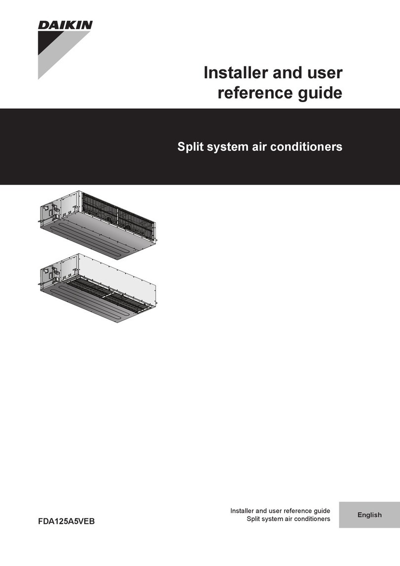
Daikin FDA125A5VEB Installer and user reference guide

Mitsubishi Electric
Mitsubishi Electric MSC-GE20VB operating instructions
Hisense
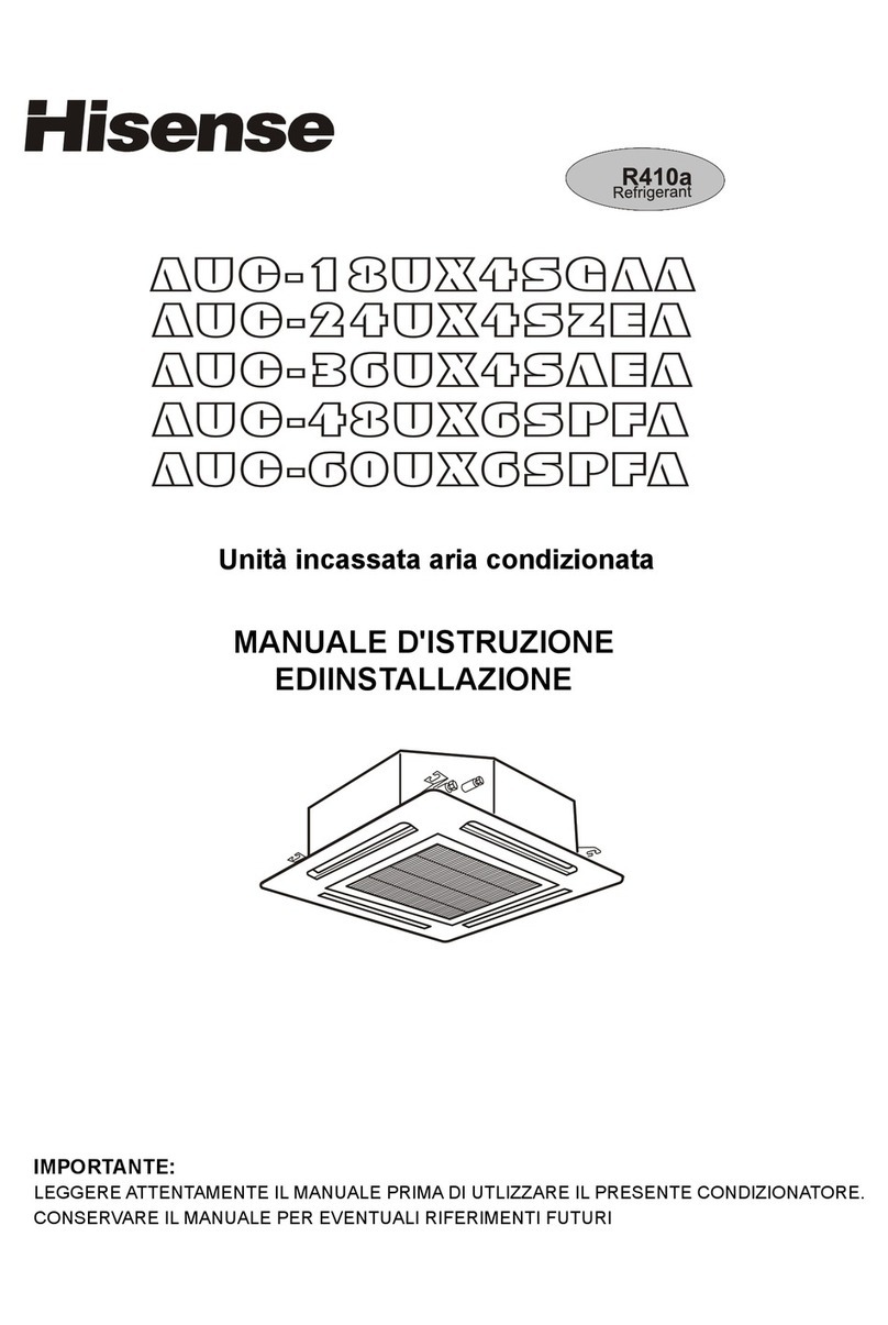
Hisense AUC-18UX4SGAA Instruction and installation manual
EMI
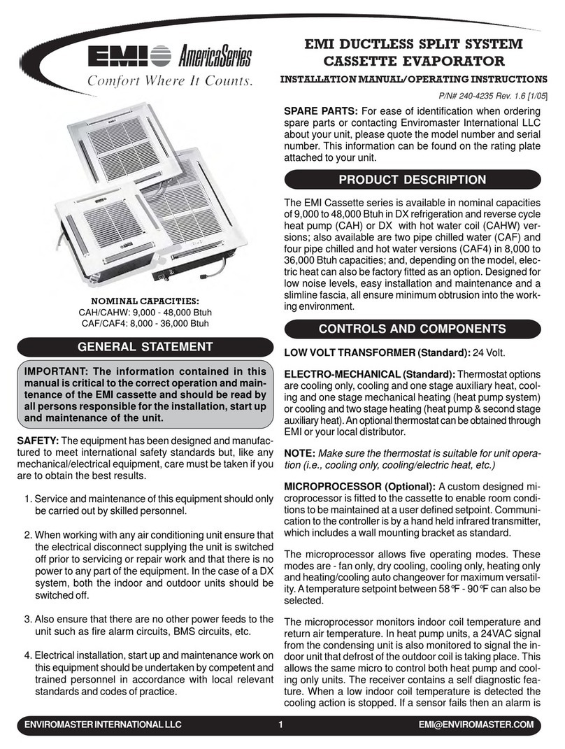
EMI WLCA operation instruction

