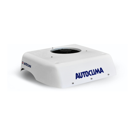
Autoclima FRESCO 5000 BACK User manual

ISTRUZIONI DI MONTAGGIO
AIR CONDITIONER ASSEMBLY
INSTRUCTIONS POUR LE MONTAGE
MONTAGE DER KLIMAANLAGE
INSTRUCCIONES DE MONTAJE


3
IT EN FR DE ES
SOMMARIO PAGINA
DIMENSIONI 5
CARATTERISTICHE TECNICHE 6
FISSAGGIO UNITÀ 7
EVAPORATORE E CONDENSATORE IN LINEA 8
SCHEMA IMPIANTO ELETTRICO 9
COLLEGAMENTO ELETTRICO 10
INCLINAZIONE EVAPORATORE 11
AVVERTENZE GENERALI 17
MONTAGGIO EVAPORATORE - OPERAZIONI PRELIMINARI 17
MONTAGGIO CONDENSATORE 18
OPERAZIONI TERMINALI 18
PROCEDURA CARICA REFRIGERANTE 18
CONTENTS PAGE
DIMENSIONS 5
NOMINAL TECHNICAL DATA 6
UNIT FIXING 7
IN LINE INSTALLATION 8
ELECTRIC DIAGRAM 9
ELECTRICAL CONNECTION 10
INCLINATION OF THE EVAPORATOR 11
GENERAL WARNINGS 19
EVAPORATOR ASSEMBLY - PRELIMINARY OPERATIONS 19
CONDENSER ASSEMBLY 20
FINISHING OPERATIONS 20
COOLANT FILLING PROCEDURE 20
NOTE/NOTE/NOTES/NOTES/NOTAS
IT Le indicazioni che si riferiscono alla DESTRA ed alla SINISTRA, sono relative al conducente del mezzo rivolto in direzione del senso di marcia.
EN The indications which refer to the RIGHT and to the LEFT concern the driver of the vehicle on the drive way.
FR Les indications qui se réferent à DROITE et GAUCHE, sont considérées par rapport au conducteur du véhicule dirigé dans le sens de la
marche, par conséquence.
DE Die Anzeigen RECHTS und LINKS sind auf den Fahrer in Fahrtrichtung bezogen.
ES Las indicaciones que hacen referencia a la DERECHA o la IZQUIERDA, se reeren al conductor del vehículo en el sentido de la marcha.

4
IT EN FR DE ES
SOMMAIRE PAGE
DIMENSIONS 5
DONNEES TECHNIQUES NOMINALE 6
FIXATION UNITÉ 7
MONTAGE EN LIGNE 8
SCHEMA ELECTRIQUE 9
BRANCHEMENT ÉLECTRIQUE 10
INCLINATION DU L’ÉVAPORATEUR 11
AVERTISSEMENTS GENERAUX 21
MONTAGE DU BLOC EVAPORATEUR - OPERATIONS PRELIMINAIRES 21
MONTAGE CONDENSEUR 22
OPERATIONS TERMINALES 22
CHARGEMENT DE REFRIGERANT / PROCEDURE 22
INHALT SEITE
DIMENSIONEN 5
TECHNISCHEN EIGENHEITEN 6
BEFESTIGUNG DER EINHEIT 7
EINBAUMÖGLICHKEIT IN LINIE 8
SCHALTSCHEMA 9
ELEKTRISCHER ANSCHLUSS 10
NEIGUNGSWINKEL DES VERDAMPFERS 11
ALLGEMEINE HINWEISE 23
MONTAGE VERDAMPFER - VORBEREITUNGEN 23
MONTAGE KONDENSATOR 24
ABSCHLIESSENDE SCHRITTE 24
EINFÜLLEN KÜHLMITTEL / VERFAHREN 24
RESUMEN PÁGINA
DIMENSIONES 5
DATOS TECNICOS 6
FIJACIÓN DE LA UNIDAD 7
MONTAJE EN LINEA 8
ESQUEMA ALAMBRICO 9
CONEXIÓN ELÉCTRICA 10
INCLINACIÓN DEL EVAPORADOR 11
ADVERTENCIAS GENERALES 25
MONTAJE EVAPORADOR - OPERACIONES PRELIMINARES 25
MONTAJE CONDENSADOR 26
OPERACIONES TERMINALES 26
CARGA DE REFRIGERANTE / PROCEDIMIENTO 26

5
IT EN FR DE ES
EVAPORATORE
EVAPORATOR
EVAPORATEUR
VERDAMPFER
EVAPORADOR
CONDENSATORE “BACK”
CONDENSER “BACK”
CONDENSEUR “BACK”
KONDENSATOR “BACK”
CONDENSADOR “BACK”
DIMENSIONI/DIMENSIONS/DIMENSIONS
DIMENSIONEN/DIMENSIONES
463
695
187
260
625 107
MAX
MIN
AUTO
MODE

6
IT EN FR DE ES
AUTO
Potenza refrigerante fornita (AUTO)
1400W (4781 BTU/h)
Supplied cooling capacity (AUTO)
Puissance frigorique (AUTO)
Kälteleistung (AUTO)
Potencia frigorica (AUTO)
Assorbimento elettrico
18A (24V)
Power consumption
Absorption éléctrique
Stromverbrauch
Intensidad absorbida
MIN
Potenza refrigerante fornita (MIN)
1100W (3757 BTU/h)
Supplied cooling capacity (MIN)
Puissance frigorique (MIN)
Kälteleistung (MIN)
Potencia frigorica (MIN)
Assorbimento elettrico
11.5A (24V)
Power consumption
Absorption éléctrique
Stromverbrauch
Intensidad absorbida
MAX
Potenza refrigerante fornita (MAX)
1600W (5464 BTU/h)
Supplied cooling capacity (MAX)
Puissance frigorique (MAX)
Kälteleistung (MAX)
Potencia frigorica (MAX)
Assorbimento elettrico
21A (24V)
Power consumption
Absorption éléctrique
Stromverbrauch
Intensidad absorbida
Funzionamento a motore
spento
Functioning with engine off Fonctionnement, le moteur
arreté
Funktion bei abgeschalte-
tem Motor
Funcionamiento con el
motor apagado
Voltaggio: 24V DC Voltage: 24V DC Voltage: 24V DC Spannung: 24V DC Voltaje: 24V DC
Gas refrigerante: R134a Refrigerant: R134a Gaz réfrigérant: R134a Kühlgas: R134a Gas refrigerante: R134a
6 velocità di ventilazione 6 ventilation speeds 6 vitesses de ventilation 6
Lüftungsgeschwindigkeiten
6 velocidades de ventilación
Controllo elettronico della
temperatura con pannello di
comando digitale
Temperature’s electronic
control with digital control
panel
Contrôle électronique de la
température avec panneau
de commande digitale
Elektronische Tempera-
turkontrolle mit digitalem
Schaltfeld
Control electrónico de la
temperatura con panel de
mandos digital
Timer per la
programmazione
funzionamento
Functioning program timer Temporisateur pour la
programmation
fonctionnement
Timer für die
Betriebsprogrammierung
Timer para la programación
funcionamiento
Telecomando Remote control Telecommande Fernbedienung Mando a distancia
Funzione di
autospegnimento con basso
voltaggio delle batterie
(Salva-batterie)
Auto-switch off with low
batterie’s voltage (Battery
saver)
Fonction d’auto-extinction
à bas voltage des batteries
(dispositif de protection des
batteries)
Selbstabschaltfunktion mit
geringer Batteriespannung
(Batterieschutz)
Función de autocierre con
bajo voltaje de las baterías
(ahorra-baterías)
Peso evaporatore 5 Kg Evaporator weight 5 Kg Poids evaporateur 5 Kg Verdampfer Gewicht 5 Kg Peso evaporador 5 Kg
Peso condensatore
"BACK" 18 Kg
Condenser "BACK"
weight 18 Kg
Poids condenseur "BACK"
18 Kg
Kondensator "BACK"
Gewicht 18
Peso condensador
"BACK" 18 Kg
CARATTERISTICHE TECNICHE/NOMINAL TECHNICAL DATA/DONNEES TECHNIQUES NOMINALE/
TECHNISCHEN EIGENHEITEN/DATOS TECNICOS

7
IT EN FR DE ES
M6
M8
1
1
2
3
4
5
6
CONDENSATORE “BACK”
CONDENSER “BACK”
CONDENSEUR “BACK”
KONDENSATOR “BACK”
CONDENSADOR “BACK”
78
EVAPORATORE
EVAPORATOR
EVAPORATEUR
VERDAMPFER
EVAPORADOR
Immagine della versione 24V
Image of 24V version
Image de la version 24V
Bild von 24V-Version
Imagen de la versiòn 24V
FISSAGGIO UNITÀ/UNIT FIXING/FIXATION UNITÉ/
BEFESTIGUNG DER EINHEIT/FIJACIÓN DE LA UNIDAD
1
Parabordo
Seal
Bourrelet
Köder
Anillo de caucho
2
Tubo in gomma
Rubber hose
Tuyau en caoutchouc
Kautschukschlauch
Tubo de caucho
3
Isolante
Insulating material
Isolant thermique
Wärmedämmung
Aislante térmico
4
Guaina protettiva
Protective coating
Revêtement de protection
Schutzumhuellung
Revestimiento de protección
5
Tubo in rame
Copper hose
Tuyau de cuivre
Kupferner Schlauch
Manguera de cobre
6
Tubo scarico acqua di condensa
Condensate water exhaust pipe
Tube d’évacuation eau de
condensation
Kondenswasserablaßrohr
Tubo de descarga del agua de
condensación
7
Vite M6 con rondella sottotesta
M6 hexagon ange bolt
Vis M6 tête hexagonal embase
M6 Sechskantschraube
Tornillo M6 de cabeza hexagonal
con reborde
8
Tappo
Cap
Bouchon
Stopfen
Tapón

8
IT EN FR DE ES
1
Parabordo
Seal
Bourrelet
Köder
Anillo de caucho
2
Tubo in gomma
Rubber hose
Tuyau en caoutchouc
Kautschukschlauch
Tubo de caucho
3
Isolante
Insulating material
Isolant thermique
Wärmedämmung
Aislante térmico
5
Tubo in rame
Copper hose
Tuyau de cuivre
Kupferner Schlauch
Manguera de cobre
6
Tubo scarico acqua di condensa
Condensate water exhaust pipe
Tube d’évacuation eau de
condensation
Kondenswasserablaßrohr
Tubo de descarga del agua de
condensación
7
Vite M6 con rondella sottotesta
M6 hexagon ange bolt
Vis M6 tête hexagonal embase
M6 Sechskantschraube
Tornillo M6 de cabeza hexagonal
con reborde
8
Tappo
Cap
Bouchon
Stopfen
Tapón
CONDENSATORE “BACK”
CONDENSER “BACK”
CONDENSEUR “BACK”
KONDENSATOR “BACK”
CONDENSADOR “BACK”
EVAPORATORE
EVAPORATOR
EVAPORATEUR
VERDAMPFER
EVAPORADOR
Immagine della versione 24V
Image of 24V version
Image de la version 24V
Bild von 24V-Version
Imagen de la versiòn 24V
11
5
33
2
6
78
EVAPORATORE E CONDENSATORE IN LINEA/IN LINE INSTALLATION/MONTAGE EN LIGNE
EINBAUMÖGLICHKEIT IN LINIE/MONTAJE EN LINEA

9
IT EN FR DE ES
C
A
B
L
G
H
M
N
S
R
V
Z
ARANCIO
AZZURRO
BIANCO
BLU
GIALLO
GRIGIO
MARRONE
NERO
ROSA
ROSSO
VERDE
VIOLA
I
C
A
B
L
G
H
M
N
S
R
V
Z
ORANGE
AZURE
WHITE
BLUE
YELLOW
GREY
BROWN
BLACK
PINK
RED
GREEN
VIOLET
GB
C
A
B
L
G
H
M
N
S
R
V
Z
ORANGE
BLEU CIEL
BLANC
BLEU
JAUNE
GRIS
MARRON
NOIR
ROSE
ROUGE
VERT
VIOLET
F
C
A
B
L
G
H
M
N
S
R
V
Z
ORANGE
HELLBLAU
WEISS
BLAU
GELB
GRAU
BRAUN
SCHWARZ
HELLROT
ROT
GRÜN
VIOLETT
D
C
A
B
L
G
H
M
N
S
R
V
Z
NARANJA
AZUL
BLANCO
TURQUI
AMARILLO
GRIS
MARRON
NEGRO
ROSA
ROJO
VERDE
VIOLETA
E
8
7
9
6
5
43
2
1
1
Batteria 24V
24V battery
Batterie 24V
Batterie 24V
Batería de 24 V
2
Fusibile 25A
25A fuse
Fusible 25A
Sicherung 25A
Fusible de 25 A
3
ECU gestione A/C
A/C management ECU
ECU gestion A/C
ECU-Management A/C
ECU de gestión A/C
4
Pannello di controllo
Control panel
Panneau de commande
Bedienfeld
Panel de control
SCHEMA IMPIANTO ELETTRICO/ELECTRIC DIAGRAM/SCHEMA ELECTRIQUE
SCHALTSCHEMA/ESQUEMA ALAMBRICO
5
Sonda di temperatura
Temperature sensor
Sonde de température
Temperaturfühler
Sonda de temperatura
6
ECU compressore
Compressor ECU
ECU compresseur
ECU-Kompressor
ECU de compresor
7
Compressore
Compressor
Compresseur
Kompressor
Compresor
8
Elettroventilatore evaporatore
Evaporator electric fan
Électro-ventilateur évaporateur
Elektrolüfter Verdampfer
Ventilador eléctrico evaporador
9
Elettroventilatore
condensatore
Condenser electric fan
Électro-ventilateur condenseur
Elektolüfter Kondensator
Ventilador eléctrico
condensador

10
IT EN FR DE ES
CABLAGGIO ELETTRICO CON CONDENSATORE “BACK”
ELECTRICAL HARNESS WITH CONDENSER “BACK”
CABLAGE ELECTRIQUE AVEC CONDENSATEUR “BACK”
ELEKTRISCHE KABELBAUM MIT KONDENSATOR “BACK”
CABLEADO ELECTRICO CON CONDENSADOR “BACK”
+
B
B
24
23
A
22
20
21
20
Pannello di controllo
Control Panel
Panneau de contrôle
Schalttafel
Panel de mando
21
Elettroventola evaporatore
Evaporator fan
Electroventilateur du l’évaporateur
Verdampferslüfter
Electroventilador del évaporador
22
Elettroventola condensatore
Condenser electric fan
Ventilateur électrique condenseur
Kondensator-Elektroflügelrad
Electroventilador condesador
23
- Batteria
- Battery
- Batterie
- Batterie
- Báteria
24
+ 24V Batteria
+ 24V Battery
+ 24V Batterie
+ 24V Batterie
+ 24V Báteria
COLLEGAMENTO ELETTRICO/ELECTRICAL CONNECTION/BRANCHEMENT ÉLECTRIQUE/
ELEKTRISCHER ANSCHLUSS/CONEXIÓN ELÉCTRICA

11
IT EN FR DE ES
Livella (Bolla aria) / Level (Spirit level) / Niveau ( à bulle d’air) / Libelle (Wasserwaage) / Nivel de aire
Ø25 Ø60
Ø20
Ø25 Ø60
Ø20
Ø25
Ø60
Ø20
Ø25
Ø60
Ø20
SI/YES/OUI/JA SI/YES/OUI/JA
SI/YES/OUI/JA NO/NEIN
INCLINAZIONE EVAPORATORE/INCLINATION OF THE EVAPORATOR/INCLINATION DU L’ÉVAPORATEUR
NEIGUNGSWINKEL DES VERDAMPFERS/INCLINACIÓN DEL EVAPORADOR

12
IT EN FR DE ES
MODALITA’ DI AGGRAFFATURA TUBI
HOSES CLAMPING MODE
MODALITE DE SERTISSAGE DES TUYAUX
LÄNGSNAHTART DER SCHLÄUCHE
GRAPADO DE LAS TUBERIAS
a
fg
b
d
c
eA
B
A B
A B

13
IT EN FR DE ES
43 5
2
NB: Prima di aggraffare il 2° raccordo sul tubo rif.2, inserire i rif. 5-3-4 (vedi pag. 7-8)
NOTICE: Before to clamp the 2nd fitting on the hose ref. 2, the refs. 5-3-4 should be
inserted (see pag. 7-8)
ATTENTION: Avant de sertir le 2eme raccord sur le tuyaux réf. 2, inserer les réfs. 5-3-4
(voir pag. 7-8)
ACHTUNG: Bevor zu dem 2er Fitting auf dem Schlauch Ref. 2 zu Klammen, sollt man
die Ref. 5-4-3 einsetzen (siehe Seite 7-8)
NOTA: Antes de grapar la 2° conexion sobre el tubo ref. 2, poner las referencias 5-3-4
(ver pag. 7-8)
NO/NEIN
h
SI/YES/OUI/JASI/YES/OUI/JA
SI/YES/OUI/JA
SI/YES/OUI/JA
NO/NEIN
NO/NEIN

14
IT EN FR DE ES
CON CENTINE / WITH RIBS / AVEC NERVURES
MIT SPRIEGELN / CON CIMBRAS
SENZA CENTINE / WITHOUT RIBS /
SANS NERVURES / OHNE SPRIEGEL / SIN CIMBRAS
1
Pannello di rivestimento / Panelling / Panneau de
revêtement / Verkleidungsplatte /
Panel de revestimiento
2
Piastra evaporatore / Evaporator’s plate / Plaque
d’évaporation / Verdampferplatte /
Plancha evaporador
3Boccola M6 / M6 bushing / Douille M6 / Buchse M6 /
Cojinete M6
4Centina di rinforzo / Reinforcing rib / Nervure de
renfort / Verstärkungsspriegel / Cimbra de refuerzo
5
Parete posteriore cabina / Cabin’s back wall / Paroi
arrière cabine / Rückwand Fahrerhaus /
Pared posterior cabina
7Distanziale / Spacer / Entretoise / Distanzscheibe /
Distanciador
8Interno cabina / Cabin’s Interior / Intérieur cabine /
Fahrerhaus Innenraum / Interior cabina
9
Passaggio per tubo scarico acqua di condensa /
Hose’s space for draining of condensed water /
Passage pour tuyau déchargement de l’eau de
condensation /
Durchgang Kondenswasserabussleitung /
Paso para tubo de desagüe agua de condensación
FIG. 1
18
5
4
7
3
2
Ø6
FIG. 2
5
Ø6
1
7
8
2
FIG. 4
5
1
8
9
Pannello di rivestimento
Panelling
Panneau de revêtement
Verkleidungsplatte
Panel de revestimiento
Asportare
Cut off
Eliminer
Abnehmen
Transportar FIG. 3

15
IT EN FR DE ES
Ø60
Ø25
Antiossidante
Antioxidant
Anti-oxydant
Oxidationsschutz
Antioxidante
Parabordo
Seal
Bourrelet
Köder
Anillo de caucho
Ø60
Ø25
FIG. 5 FIG. 6
FIG. 8
FIG. 7
FIG. 9
SIGILLARE ACCURATAMENTE
SEAL ACCURATELY
SCELLER TRÈS SOIGNEUSEMENT
SEHR SORGFÄLTIG ABDICHTEN
SELLAR CON SUMO CUIDADO

16
IT EN FR DE ES
Tappo
Cap
Bouchon
Stopfen
Tapón
Tappo
Cap
Bouchon
Stopfen
Tapón
Tappo
Cap
Bouchon
Stopfen
Tapón
CONDENSATORE BACK
BACK CONDENSER
CONDENSEUR ARRIÈRE
RÜCKSEITIGER KONDENSATOR
CONDENSADOR TRASERO
EVAPORATORE
EVAPORATOR
EVAPORATEUR
VERDAMPFER
EVAPORADOR
M5

17
IT EN FR DE ES
17
AVVERTENZE GENERALI
Per l'installazione, è importante attenersi scrupolosamente alle indicazioni riportate nel presente manuale.
Il costruttore declina ogni responsabilità, in caso di danni a cose e persone provocati da installazioni o variazioni non conformi
dell'impianto.
Sulla dima evaporatore fornita con il set di montaggio sono segnati, oltre alle asole per il suo ssaggio, anche 2 fori Ø60 e Ø20 per il
passaggio piastra raccordi e tubo scarico acqua di condensa. Accertarsi che non esistano ingombri od interferenze nei punti dove
si dovranno eseguire questi 2 fori.
La distanza tra il blocco evaporatore (all’interno della cabina) ed il blocco condensatore (all’esterno) è vincolata dalla lunghezza del
tubo in rame di collegamento.
MONTAGGIO EVAPORATORE - OPERAZIONI PRELIMINARI
SCEGLIERE LA POSIZIONE PIU’ IDONEA PER IL MONTAGGIO DEL BLOCCO EVAPORATORE.
IN PRESENZA DI CENTINE O TRAVERSE DI RINFORZO dietro al pannello di rivestimento interno (VEDI FIG.1 PAG.14), appoggiare la
dima in cartoncino fornita contro la parete posteriore. SCEGLIERE 4 PUNTI DI FISSAGGIO TRA LE 12 ASOLE presenti sulla dima, 2 PER
PARTE, in modo che siano IL PIU’ LONTANO POSSIBILE TRA DI LORO.
Accertarsi che almeno i 2 punti di ssaggio SUPERIORI (se non tutti e 4) siano posizionati in corrispondenza di una centina di rinforzo.
Segnare i punti sul pannello ed eseguire i 4 fori Ø6 (NON PASSANTI). Allargare quanto basta i fori ed inserire le boccole a mandrinare
M6 no ad incassarle nelle centine.
N.B. Eventualmente (se necessario) introdurre davanti alle boccole, un distanziale di altezza adeguata per evitare che il pannello di rive-
stimento si possa deformare durante il ssaggio del blocco evaporatore.
NEL CASO IN CUI NON VI SIANO CENTINE DI RINFORZO tra il pannello di rivestimento e la parete posteriore della cabina (VEDI FIG.2
PAG.14) dopo aver individuato il punto più idoneo per il montaggio dell’evaporatore, scegliere i punti di ssaggio (utilizzando la dima
fornita) (2 PER PARTE, IL PIÙ LONTANO POSSIBILE TRA DI LORO) ed eseguire 4 FORI Ø6 PASSANTI.
N.B. Eventualmente (se necessario) introdurre distanziali di altezza adeguata per evitare che il pannello di rivestimento si possa deformare
durante il ssaggio del blocco evaporatore.
DOPO AVER ESEGUITO I FORI PER IL FISSAGGIO DELL’EVAPORATORE, segnare i CENTRI per eseguire i rimanenti 2 fori indicati
sulla dima (Ø60 e Ø20). Realizzare SOLO SUPERIORMENTE, un foro Ø6 PASSANTE.
Operando dall’esterno, mediante una fresa a tazza, allargare a Ø60 il foro Ø6 (sia sulla parete in lamiera che sul rivestimento interno)
che sarà poi utilizzato per il passaggio piastra raccordi (VEDI FIG.4 PAG.14)
Operando dall’interno, eseguire un foro Ø6 PASSANTE in corrispondenza del CENTRO INFERIORE, INCLINANDO OPPORTUNA-
MENTE L’ATTREZZO (VEDI FIG.4 PAG.14).
N.B: QUEST’ULTIMO ACCORGIMENTO È’ NECESSARIO PER AGEVOLARE IL PASSAGGIO DEL TUBO SCARICO ACQUA DI CON-
DENSA CHE DEVE SCORRERE CORRETTAMENTE INCLINATO.
Allargare quindi a Ø25 il foro eseguito sulla parete in lamiera e a Ø20 lo stesso foro sul pannello di rivestimento interno (per l’in-
serimento del tubo scarico condensa) (VEDI FIG.4 PAG.14)
N.B. NEL FORARE, PRESTARE MOLTA ATTENZIONE PER NON DANNEGGIARE LA TAPPEZZERIA.
Operando dall’esterno, DISTRIBUIRE ANTIOSSIDANTE SUL PERIMETRO DI TUTTI I FORI PASSANTI ESEGUITI ed inserire intorno
al foro Ø60 ed al foro Ø25 le guarnizioni parabordo fornite (VEDI FIG.5-6 PAG.15).
Introdurre il tubo scarico acqua di condensa attraverso l’apertura eseguita sul pannello di rivestimento interno e farlo fuoriuscire
attraverso il foro Ø25 con gommino, verificandone la corretta pendenza.
Togliere la copertura ed appoggiare l’evaporatore contro la parete posteriore del veicolo, facendo fuoriuscire la piastra raccordi attraverso
il foro Ø60 eseguito in precedenza.
Raccordare il tubo scarico acqua di condensa al beccuccio presente sulla vaschetta di scarico acqua sotto l’evaporatore
PRIMA DI BLOCCARE DEFINITIVAMENTE il blocco evaporatore contro il pannello, verificare la sua corretta inclinazione, appoggiando
una livella (bolla d’aria) sulla parete superiore, trasversalmente rispetto ad esso.
Quest’ultimo DEVE SEMPRE RIMANERE VERTICALE O LIEVEMENTE INCLINATO VERSO LA PARETE POSTERIORE, MAI INCLINATO
VERSO L’AVANTI: se così risultasse CORREGGERE interponendo distanziali di compensazione adeguati nei punti di ssaggio, no a
raggiungere la posizione ottimale (VEDI PAG.11)
Dopo aver eseguito i vari collegamenti, ssare l’evaporatore alla parete di supporto mediante viterie fornite dall’interno verso l’esterno
distribuendo in modo molto accurato sigillante sul perimetro dei fori ed intorno alle viti.

18
IT EN FR DE ES
18
MONTAGGIO CONDENSATORE
Togliere la copertura del blocco condensatore.
Appoggiare la dima fornita dietro la cabina, nel punto ritenuto più idoneo per il montaggio del condensatore.
PRESTARE PARTICOLARE ATTENZIONE ALLA POSIZIONE DEL CONDENSATORE IN MODO CHE NON VI SIANO INTERFERENZE
TRA LO STESSO E GLI ORGANI FISSI ANCORATI SUL TELAIO DURANTE LE OSCILLAZIONI O IL RIBALTAMENTO DELLA CABINA.
Scegliere 4tra le 11 asole presenti sulla dima del condensatore, 2 PER PARTE, IN MODO CHE SIANO IL PIÙ LONTANO POSSIBILE
TRA DI LORO, CERCANDO DI FARLE COINCIDERE CON LE NERVATURE PRESENTI SULLA CARROZZERIA.
In caso di dislivelli sulla parete posteriore della cabina, nella zona di appoggio del condensatore, compensare con distanziali di
adeguata misura.
Segnare sulla carrozzeria i 4 punti di ssaggio ed eseguire i fori Ø13. Distribuire antiossidante sul perimetro dei fori, quindi inserire 4
inserti ingabbiati M8 forniti, tirandoli opportunamente. COSPARGERE SIGILLANTE IN MODO ACCURATO INTORNO AI PUNTI DI
FISSAGGIO (VEDI FIG.7 PAG.15).
Appoggiare e bloccare il condensatore mediante le viti fornite con relative rondelle.
OPERAZIONI TERMINALI
SIGILLARE MOLTO ACCURATAMENTE il foro Ø60 con guarnizione parabordo eseguito sulla carrozzeria del veicolo ed il foro eseguito
per il passaggio del tubo scarico acqua di condensa, mediante schiuma poliuretanica e silicone.
Proteggere con la guaina corrugata piccola il tubo capillare dove necessario.
Montare IL TERMINALE 90°: eseguire 3 fori sul bordo esterno nei punti più idonei per il suo ssaggio, forando anche la carrozzeria retrostante.
Applicare bene il sigillante su tutto il perimetro di contatto del terminale contro la parete del veicolo; applicare antiossidante e
sigillante intorno ai fori eseguiti sulla carrozzeria quindi, dopo aver posizionato il terminale, ssarlo mediante le viti autolettanti fornite.
Fissare il tubo refrigerante alla carrozzeria mediante la fascetta fermatubo con viterie fornite, forando in opera, dopo aver applicato
antiossidante e sigillante adeguato (VEDI FIG.9 PAG.15)
Montare, all’interno della cabina, la copertura del blocco evaporatore (VEDI PAG.16).
Montare all’esterno la copertura del blocco condensatore (VEDI PAG.16)
PROCEDURA CARICA REFRIGERANTE
Prima di eseguire la carica di refrigerante, (attraverso il raccordo di carica presente sul blocco condensatore) effettuare 30 min.
di vuoto.
Immettere nel circuito circa 500 grammi di R134a.
Accendere il FRESCO 5000 BACK per circa 10 minuti prima di scollegare il tubo di carica.
A carica refrigerante ultimata, verificare l’assenza di perdite ed il corretto funzionamento dell’impianto.

19
IT EN FR DE ES
19
GENERAL WARNINGS
When installing, be sure to follow carefully the instructions given in this manual.
The manufacturer declines all responsibilities for damage to equipment or people caused by non-standard system installations
or modifications.
On the evaporator template supplied together with the assembly set, are indicated, besides the slotted holes for fastening the evaporator,
2 Ø60 and Ø20 holes for the connections plate and the draining of condensed water. Make sure there are no obstructions or obstacles
on the spots where these 2 holes will be made.
The distance between the evaporator block (inside the cabin) and the condenser block (on the outside) depends on the length of the
connection copper hose.
EVAPORATOR ASSEMBLY - PRELIMINARY OPERATIONS
CHOOSE THE BEST POSITION FOR ASSEMBLING THE EVAPORATOR BLOCK.
IN THE PRESENCE OF REINFORCING RIBS OR CROSSBARS behind the inner panelling (SEE FIG.1 PAG.14), lay the carton template
against the back wall. CHOOSE 4 FASTENING POINTS OUT OF THE 12 slotted holes on the template, 2 ON EACH SIDE, choosing them
AS FAR AS POSSIBLE FROM EACH OTHER.
Make sure that at least the 2 UPPER fastening points (if not all 4) are placed in correspondence of a reinforcing rib. Mark the spots
on the panel and make the 4 Ø6 holes (NON FEED-THROUGH). Widen the holes sufficiently and insert the expanding M6 bushings
until they are set in the ribs.
N.B. In case, place an adequate spacer before the bushings in order to avoid the deformation of the panelling during the fastening of the
evaporator.
IN CASE THERE ARE NO REINFORCING RIBS between the panelling and the cabin’s back wall (SEE FIG.2 PAG.14), after locating the
most suitable spot for the installation of the evaporator choose the fastening holes (using the provided template) (2 ON EACH SIDE, AS
FAR AS POSSIBLE FROM EACH OTHER) and make 4 Ø6 holes FEED-THROUGH.
N.B. If it is necessary, they may eventually insert some spacers with a proper height, to avoid the covering panel to become distorted
when xing the evaporator block.
AFTER MAKING THE HOLES NEEDED TO FASTEN THE EVAPORATOR, mark the CENTRES on the template to make the 2 remaining
holes (Ø60 and Ø20). Make a FEED-THROUGH Ø6 hole ONLY ON THE UPPER PART.
Operating from the outside, and with the aid of a bucket mill, widen the Ø6 hole to make it Ø60 both on the steel wall and on the internal
panel (which will then be used for the transit of the connections plate) (SEE FIG.4 PAG.14).
Operating from the inside, make a FEED-THROUGH Ø6 hole in correspondence of the LOWER CENTRE, SUITABLY TILTING THE
TOOL (SEE FIG.4 PAG.14)
N.B.: THIS PRECAUTION IS NECESSARY TO FACILITATE THE TRANSIT OF THE HOSE FOR THE DRAINING OF CONDENSED
WATER WHICH MUST HAVE A PROPER SLOPE.
Then expand the hole made in the metal wall to Ø25 and the same wall on the inner covering panel to Ø20 (for housing the con-
densation drainage pipe) (SEE FIG.4 PAG.14)
N.B.: WHILE MAKING THE HOLE PAY SPECIAL ATTENTION IN ORDER TO AVOID DAMAGING THE UPHOLSTERY.
Operating from the outside, PUT ANTIOXIDANT AROUND ALL THE FEED-THROUGH HOLES PREVIOUSLY MADE and insert the
grommets supplied around the holes Ø60 and Ø25 (SEE FIG.5-6 PAG.16).
Introduce the condensation drain pipe through the opening made on the internal covering panel and poke it through the Ø25 hole
with grommet insert, checking the correct slope.
Remove the covering and lean the evaporator against the vehicle’s back wall bringing out the connections plate through the Ø60 hole
previously made.
Connect the condensation drainage pipe to the lip on the water drainage tray under the evaporator.
BEFORE BLOCKING THE EVAPORATOR UNIT ONCE FOR ALL against the panel make sure it has a proper slope, placing a level
(spirit-level) crosswise on the upper part.
IT MUST ALWAYS BE VERTICAL OR SLIGHTLY LEANING TOWARDS THE BACK WALL, BUT NEVER FORWARD: should it be so
MAKE A CORRECTION inserting adequate spacers in the fastening spots, until the optimal position is reached. (SEE PAG.11).
After making the connections, t the evaporator to the rear wall through the supplied screws. Insert the screws from the inside towards
the outside spreading the sealant very carefully around the holes and around the screws.

20
IT EN FR DE ES
20
CONDENSER ASSEMBLY
Remove the condenser cover.
Rest the template provided behind the cab, in the point considered most suitable for the assembly of the condenser.
PAY SPECIAL ATTENTION TO THE CONDENSER’S POSITION IN ORDER TO AVOID INTERFERENCE BETWEEN IT AND THE
MACHINE-MEMBERS FIXED ON THE CHASSIS, DURING SWINGING OR DURING CABIN’S OVERTURNING.
Choose 4among the 11 slots from the condenser’s template, 2 ON EACH SIDE, SO THAT THEY ARE AS FAR AS POSSIBLE FROM
EACH OTHER, TRIYING TO MATCH THEM WITH THE RIBS PRESENT IN THE BODY OF THE VEHICLE.
Should there be differences of levels on the cabin’s back wall, in the condenser’s area, use adequate spacers.
Mark the 4 fastening spots on the chassis and make the Ø13 holes. Spread antioxidant around the holes, then insert the 4 M8 caged inserts
given, pulling them properly. SPREAD THE SEALANT VERY CAREFULLY AROUND THE FASTENING POINTS (SEE FIG.7 PAG.15)
Rest and block the condenser using the screws supplied with relative washers.
FINISHING OPERATIONS
SEAL the Ø60 hole with grommet made on the vehicle’s chassis and the hole made for the draining of condensed water VERY ACCU-
RATELY with polyurethane foam and silicone.
Protect with the small corrugated jacket the capillary hose where required.
Assemble the 90° TERMINAL: make 3 holes on the outer border on the most appropriate points for its fastening, drilling the bodywork
at the back. Spread the sealant well on all the area of contact between the terminal and the vehicle’s wall; put the antioxidant and
the sealant around the holes made on the chassis, then fasten it with the self-tapping screws 3.9x16 given after the terminal has been
positioned.
Fasten the coolant pipe to the bodywork using the pipe clamp with the screws supplied, drilling the necessary holes, after applying
an appropriate rustproof seal (SEE FIG.9 PAG.15)
Assemble the cover of the evaporator block inside the cab (SEE PAG.16)
Install to the outside the covering of the condenser block (SEE PAGE 16)
COOLANT FILLING PROCEDURE
Before to make the refrigerating charge, (through the charge id fitting placed on the condenser block) make 30 min. vacuum cycle.
Put into the circuit ca. 500 grams of R134a.
Switch the FRESCO 5000 BACK on for ca. 10 minutes before to disconnect the charging hose.
When the refrigerating charge cycle is over, the leakages and the correct operation of the system should be checked.
Other manuals for FRESCO 5000 BACK
1
Table of contents
Languages:
Other Autoclima Air Conditioner manuals
Popular Air Conditioner manuals by other brands

Sanyo
Sanyo KS2432 instruction manual
Daikin
Daikin FFQ09Q2VJU Operation manual
Daikin
Daikin FDA125A5VEB Installer and user reference guide

Mitsubishi Electric
Mitsubishi Electric MSC-GE20VB operating instructions
Hisense
Hisense AUC-18UX4SGAA Instruction and installation manual
EMI
EMI WLCA operation instruction


