Autoclima 12121583 User manual
FIAT
DUCATO
Ampliamento impianto di condizionamento per veicoli con:
- Impianto cabina originale predisposto per collegamento 2° evaporatore (cod. 12121583)
- Impianto cabina originale non predisposto per collegamento 2° evaporatore (cod. 12121605)
- Impianto cabina Autoclima (cod. 12121606)
Extension of air-conditioning system for vehicles with:
- Original cab system prepared for connection of 2nd evaporator (cod. 12121583)
- Original cab system not prepared for connection of 2nd evaporator (cod. 12121605)
- Autoclima cab system (cod. 12121606)
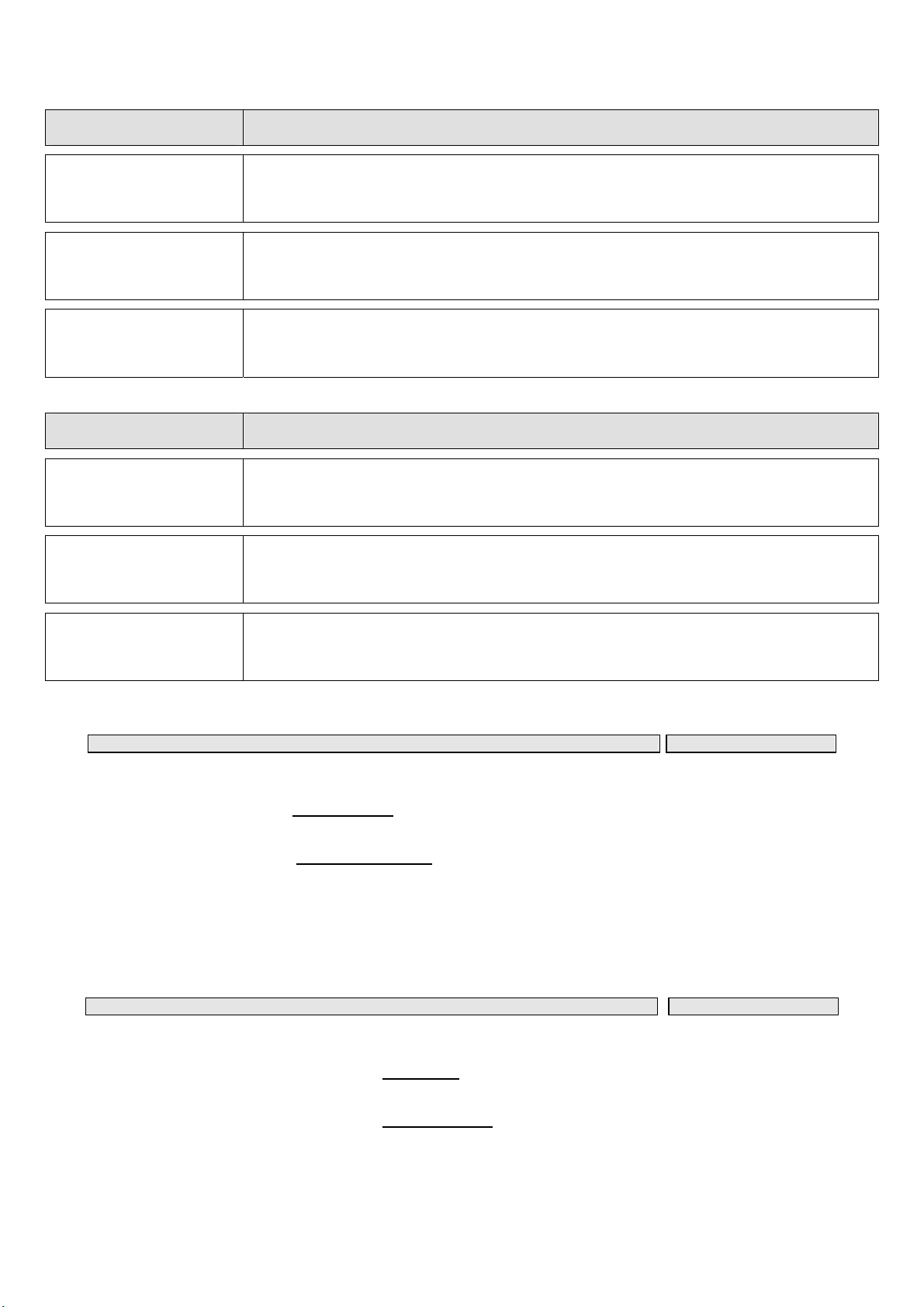
COD. A/C DESCRIZIONE
12121583
A/C con impianto cabina ORIGINALE predisposto per collegamento 2° evaporatore
+
evaporatore supplementare (MISTRAL)
12121605
A/C con impianto cabina ORIGINALE NON predisposto per collegamento 2° evaporatore
+
evaporatore supplementare (MISTRAL)
12121606
A/C con impianto cabina AUTOCLIMA
+
evaporatore supplementare (MISTRAL)
COD. A/C DESCRIPTION
12121583
A/C with ORIGINAL cab system prepared for connection of 2nd evaporator
+
supplementary rear evaporator (MISTRAL)
12121605
A/C with ORIGINAL cab system NOT prepared for connection of 2nd evaporator
+
supplementary rear evaporator (MISTRAL)
12121606
A/C with AUTOCLIMA cab system
+
supplementary rear evaporator (MISTRAL)
SOMMARIO PAG.
Istruzioni di montaggio evaporatore posteriore 1 - 5
Impianto cabina originale PREDISPOSTO per collegamento 2° evaporatore +
evaporatore posteriore 6 - 7
Impianto cabina originale NON PREDISPOSTO per collegamento 2° evaporatore
+ evaporatore posteriore 8 - 9
Impianto cabina AUTOCLIMA + evaporatore posteriore 8
10 - 11
Schema collegamenti elettrici 12
CONTENTS PAG.
Assembly instructions of supplementary rear evaporator 1 - 5
Cooling system with original cab system PREPARED for connection of 2nd
evaporator + supplementary rear evaporator 6 - 7
Cooling system with original cab system NOT PREPARED for connection of 2nd
evaporator + supplementary rear evaporator 8 - 9
Cooling system with AUTOCLIMA cab system + supplementary rear evaporator 8
10 - 11
Electrical wiring diagram 12

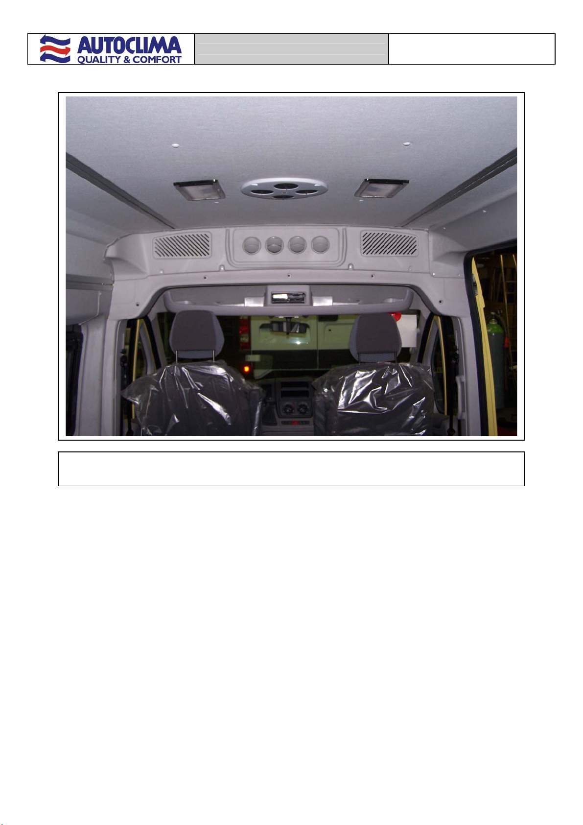
FIAT DUCATO CON 2°
EVAPORATORE
1
Senso di marcia
Drive way
Montare la cornice sul blocco evaporatore utilizzando 4 rivetti
2,9x9
Fit the frame supplied to the evaporator unit using 4 2.9x9
rivets
3inserti esagonali M.6
3 M.6 hexagonal inserts
4 inserti ingabbiati M.6 (allargare i fori orig. a Ø10)
4 M.6 caged inserts (enlarge holes to Ø10)
Fissare la staffa supporto evaporatore mediante 7 viti
M.6x20 + rond. piana Ø6xØ18 + rond. ond. Ø6
Fasten the evaporator support post in place using 7
M.6x20 screws + Ø6xØ18 flat washer + Ø6 undulated
washer

FIAT DUCATO CON 2°
EVAPORATORE
2
Modificare il pianale di appoggio asportando la parte
indicata in figura.
Fissare quindi l’evaporatore alla staffa di supporto
utilizzando 4 viti autofilettanti 2 principi 5x14.
Change the edge of the support panel, removing the
p
art shown in the figure.
Fasten the evaporator to the support post using 4
self-threading screws 5x14 - 2 principles.
Eseguire un foro Ø70 sulla copertura in
plastica all’interno del montante in lamiera dx.
Make a Ø70 hole in the plastic cover inside
the right-hand metal strut.
Eseguire un’asola sulla parte inferiore del montante
in lamiera dx ed inserire la guarnizione parabordo.
Create a slot in the lower part of the right-hand metal
strut and insert the edge protection seal.
A
pplicare la guarnizione adesiva fornita,
lungo tutto il profilo della cornice.
A
pply the adhesive seal supplied along the
p
rofile of the evaporator frame.
FIAT DUCATO CON 2°
EVAPORATORE
3
Vite M.6x14 + Ø6 rond. ondulata
M.6x14 screw + Ø6 undulated washer
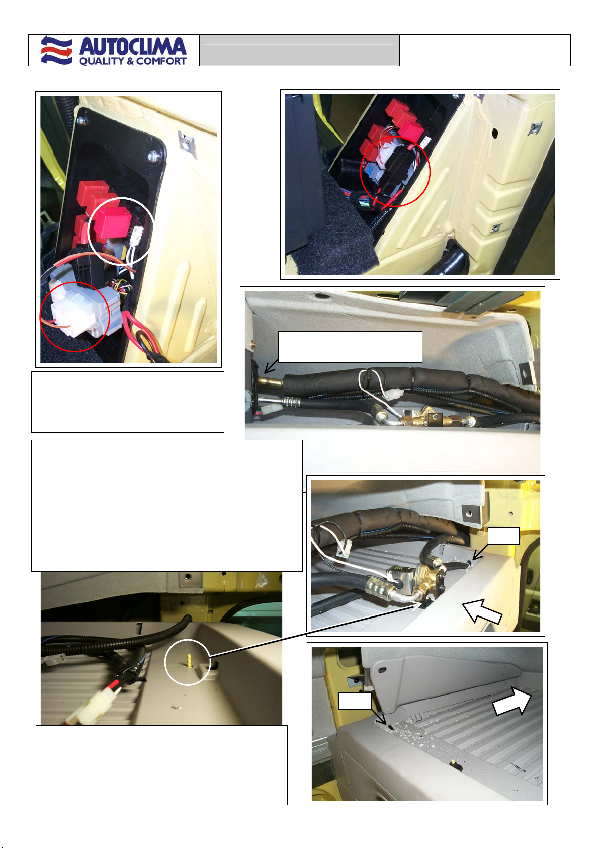
Inserire relay e fusibile nelle predisposizioni
esistenti sul montante dx. Eseguire i collegamenti
elettrici.
Insert the relay and fuse on the existing right-hand
strut. Make the electrical connections.
Ø20
Far scorrere i tubi G6 e G12 e collegare quest’ultimo alla valvola di espansione.
Fissare la staffetta ad “L” fornita alla vite originale mediante un dado in plastica.
Fissare sulla staffa l’elettrovalvola fornita utilizzando le viti T.C.E.I. 8/32” con relative
rondelle.
Collegare il tubo G6 L. 350 alla valvola di espansione e all’elettrovalvola.
Slide in pipe G6 and G12 and connect the latter to the expansion valve.
Fasten the L-shaped post supplied to the original screw using a plastic nut.
Fasten the solenoid supplied to the post using the 8/32” T.C.E:I. screws with relative
washers.
Connect pipe G6 L. 350 to the expansion valve and the solenoid.
G6 L.350
Ø20
Eseguire 2 fori Ø20 sul pianale di appoggio evaporatore a dx e a sx
per il passaggio dei tubi scarico acqua di condensa (che dovranno
essere collegati alle predisposizioni laterali dell’evaporatore).
Make 2 Ø20 holes in the evaporator support panel on the right and
left-hand sides for the passage of the condensation discharge pipes
(which must be connected to the lateral connections on the
evaporator).
FIAT DUCATO CON 2°
EVAPORATORE
4
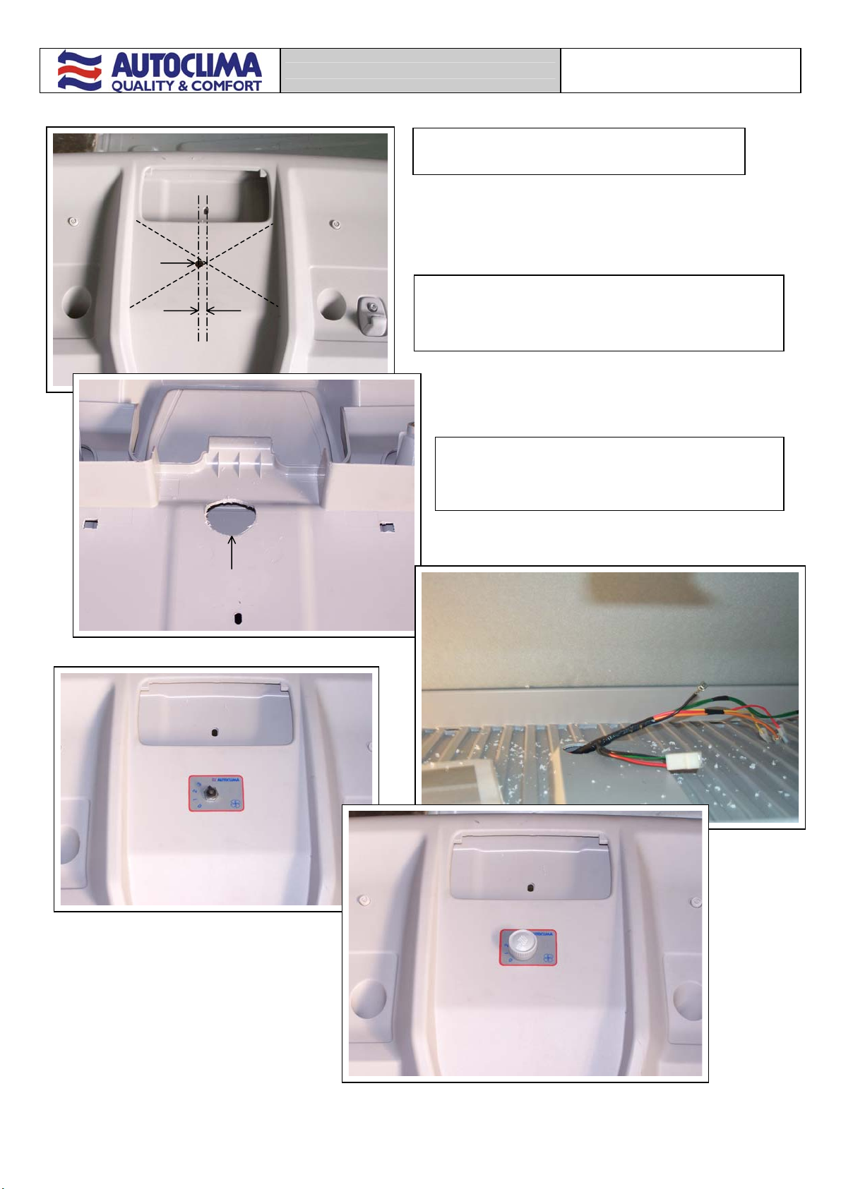
10
Ø10
Eseguire un foro Ø10 sul tunnel in plastica tra le alette parasole.
Make a Ø10 hole in the plastic tunnel between the sunshades.
Ø35
Eseguire un foro Ø35 sul pannello superiore in corrispondenza del foro
Ø10 appena eseguito.
Make a Ø35 hole in the upper panel in combined with the Ø10 made
earlier.
Montare il selettore, collegare il cablaggio elettrico e farlo
fuoriuscire dal foro Ø35 eeguito.
Fit the selector, connect the electric wiring and slide it through the
Ø35 hole made earlier.
FIAT DUCATO CON 2°
EVAPORATORE
5
Montare la copertura evaporatore utilizzando viti autofilettanti 3,5x15,9.
Fit the evaporator cover using 3.5x15.9 self-threading screws.

FIAT DUCATO CON 2°
EVAPORATORE
6
Collegare i tubi G6-G12 ai raccordi già presenti in origine.
Connect pipes G6-G12 to the original connections.
SOLO PER VEICOLI CON IMPIANTO CABINA ORIGINALE PREDISPOSTO PER COLLEGAMENTO 2° EVAPORATORE
ONLY FOR VEHICLES WITH ORIGINAL CAB SYSTEM PREPARED FOR CONNECTION OF 2ND EVAPORATOR
FIAT DUCATO CON 2°
EVAPORATORE
7
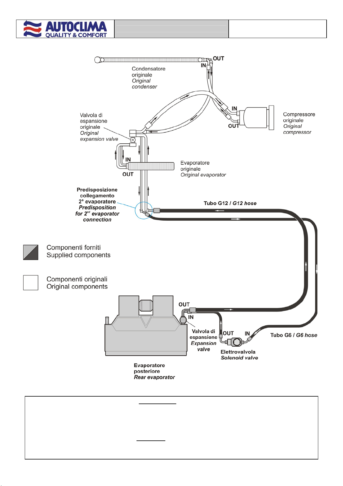
IMPIANTO CABINA ORIGINALE PREDISPOSTO PER COLLEGAMENTO 2° EVAPORATORE
+
EVAPORATORE SUPPLEMENTARE (MISTRAL)
ORIGINAL CAB SYSTEM PREPARED FOR CONNECTION OF 2ND EVAPORATOR
+
SUPPLEMENTARY REAR
E
VAPORATO
R
(
MISTRAL
)

FIAT DUCATO CON 2°
EVAPORATORE
8
Interporre tra la valvola di espansione e i tubi G12/G6 di collegamento evaporatore cabina, il blocchetto raffigurato.
Collegare ad esso anche i tubi G12/G6 provenienti dall’evaporatore posteriore.
Insert the block shown between the expansion valve and pipes G12/G6 for connection to the cab evaporator.
A
lso connect pipes G12/G6 from the rear evaporator to the same block.
Valvola di
espansione
Expansion
valve
G12-G6 AC cabina
G12-G6 AC cab
Tubo G12 -Tubo G6 collegamento evaporatore posteriore.
Pipe G12 – Pipe G6 rear evaporator connection.
SOLO PER VEICOLI CON IMPIANTO CABINA ORIGINALE NON PREDISPOSTO PER COLLEG
A
MENTO 2° EVAPORATORE
O
CON IMPIANTO CABINA AUTOCLIMA
ONLY FOR VEHICLES WITH ORIGINAL CAB SYSTEM NOT PREPARED FOR CONNECTION OF 2ND EVAPORATOR
OR
WITH AUTOCLIMA CAB SYSTEM
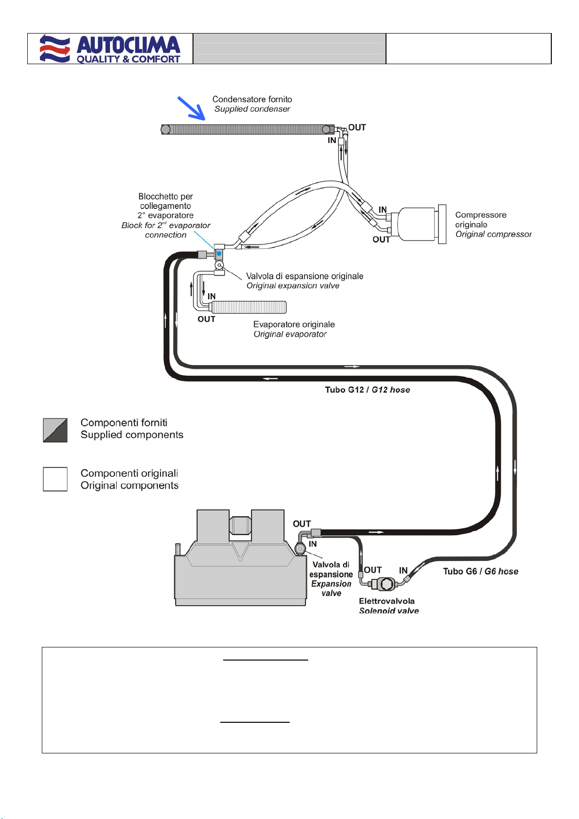
SOLO PER VEICOLI CON IMPIANTO CABINA
ORIGINALE NON PREDISPOSTO PER
COLLEGAMENTO 2° EVAPORATORE
Smontare ed eliminare il condensatore frontale,
sostituirlo con quello in dotazione.
ONLY FOR VEHICLES WITH ORIGINAL CAB
SYSTEM NOT PREPARED FOR CONNECTION
OF 2ND EVAPORATOR
Dismantle and eliminate the front condenser,
replacing it with that supplied.
FIAT DUCATO CON 2°
EVAPORATORE
9
IMPIANTO CABINA ORIGINALE NON PREDISPOSTO PER COLLEGAMENTO 2° EVAPORATORE
+
EVAPORATORE SUPPLEMENTARE (MISTRAL)
ORIGINAL CAB SYSTEM NOT PREPARED FOR CONNECTION OF 2ND EVAPORATOR
+
SUPPLEMENTARY REAR
E
VAPORATO
R
(
MISTRAL
)
FIAT DUCATO CON 2°
EVAPORATORE
10
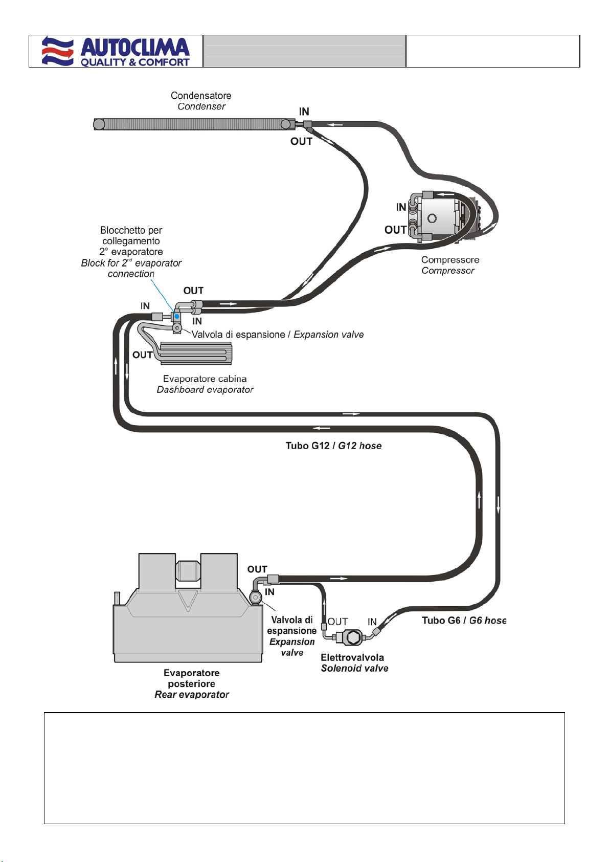
IMPIANTO CABINA AUTOCLIM
A
+
EVAPORATORE SUPPLEMENTARE (MISTRAL)
AUTOCLIMA CAB SYSTEM
+
SUPPLEMENTARY REAR
E
VAPORATO
R
(
MISTRAL
)

FIAT DUCATO CON 2°
EVAPORATORE
11
IMPIANTO CABINA AUTOCLIMA + EVAPORATORE SUPPLEMENTARE (MISTRAL)
AUTOCLIMA CAB SYSTEM + SUPPLEMENTARY REAR EVAPORATOR (MISTRAL)

FIAT DUCATO CON 2°
EVAPORATORE
12
Schema elettrico / Wiring diagram
C ORANGE
A AZURE
B WHITE
L BLUE
G YELLOW
H GREY
M BROWN
N BLACK
S PINK
R RED
V GREEN
Z VIOLET
2
80817521 - Maggio 2007 AC 12121583
AUTOCLIMA S.p.A.
Via Cavalieri di Vittorio Veneto, 15 Tel. (011) 944.32.10
Telefax (011) 944.32.30
10020 CAMBIANO (TO) Italy
This manual suits for next models
2
Other Autoclima Automobile Accessories manuals


