Mennekes AMTRON Xtra User manual


1
Wechs el ein-auf z weis palti g
About this Document
© Copyright MENNEKES Elektrotechnik GmbH & Co. KG
Content subject to changes without notice.
This document is protected by copyright. It helps to ensure
the device is used safely and efficiently by the user. The
contents may not be duplicated or reproduced, in whole or
in part, without the prior consent of the copyright holder.
Document symbols
Listing
Check / Result
Tip
Reference to another page in this document
Reference to another document
Table of Contents
1General.................................................................. 2
1.1 Structure of the installation instructions .................. 3
2Safety .................................................................... 3
2.1 General Safety Information ..................................... 3
2.2 Safety Information .................................................. 4
2.3 Intended Use........................................................... 4
2.4 Qualification of Personnel ....................................... 4
2.5 Warranty................................................................. 4
2.6 Returning Devices ................................................... 4
3Product Description.............................................. 5
3.1 General information................................................ 5
3.2 Optional equipment ................................................ 5
3.3 Identification Plate .................................................. 6
3.4 Delivery Contents.................................................... 7
3.5 Assembly................................................................. 7
3.5.1 Exterior view............................................... 7
3.5.2 Interior view................................................ 8
3.6 Components ........................................................... 9
3.6.1 Front panel ................................................. 9
3.6.2 HC controller ............................................ 10
4Technical Data .................................................... 11
4.1 General data ......................................................... 11
4.1.1 Maximum cable cross-sections at terminals11
4.2 Ambient conditions............................................... 11
5Installation.......................................................... 12
5.1 Choice of location................................................. 12
5.2 Unpacking ............................................................ 12
5.3 Opening the charging station................................ 13
5.4 Assembly .............................................................. 13
5.4.1 Minimum distances .................................. 13
5.4.2 Installing the supply cable......................... 13
5.4.3 Installing the charger station on the wall .. 14
5.5 Electrical connection ............................................. 15
5.5.1 Voltage supply / supply network connection
................................................................ 15
5.5.2 Safeguarding and personal protection ...... 15
5.5.3 Terminals.................................................. 16
5.5.4 LAN connection........................................ 17
5.5.5 Tariff-switching signal............................... 17
5.5.6 RS485 bus ................................................ 18
6Commissioning................................................... 19
6.1 Turning on the charging station............................ 19
6.2 Setting up the network connection....................... 19
6.2.1 LAN connection (Ethernet)........................ 19
6.2.2 WLAN connection .................................... 19
6.3 Configuration of the charging station ................... 19
6.3.2 Access over LAN ....................................... 19
6.3.3 Calling up the service interface................. 20
6.3.4 Setting up a direct connection (access point
mode)....................................................... 20
6.3.5 Setting up the connection to the wireless
home network.......................................... 21
6.3.6 Time synchronisation ................................ 21
6.3.7 Menu description ..................................... 22
6.4 MENNEKES Charge APP........................................ 26
6.4.1 Requirements ........................................... 26
6.4.2 Automatic connection of the Charge APP. 26
6.4.3 Manual connection of the Charge APP ..... 27
6.5 Checking the charging station .............................. 28
6.6 Closing the charging station ................................. 29
7Operation............................................................ 29
7.1 General information on operation......................... 29
7.2 LED Info bar.......................................................... 30
7.3 Multi-function button ........................................... 31
7.3.1 Terminating an on-going charging process31
7.3.2 Re-activating the residual current circuit
breaker and circuit breaker....................... 31
7.3.3 Testing the integrated residual current circuit
breaker (RCCB)......................................... 31
7.4 Description of operating modes ............................ 32
7.4.1 Settings in operating mode "Energy
Manager"................................................. 37
7.5 Charging the vehicle ............................................. 38
7.5.1 Charging without authorisation................ 38
7.5.2 Authorisation with RFID............................ 38
7.5.3 Authorisation with Charge APP ................ 38
7.5.4 Mode 3 charging...................................... 39
7.5.5 Terminating the charging process............. 39
7.5.6 Power failure during charging process ...... 39

2
7.6 Managing RFID cards ............................................ 40
7.6.1 Adding RFID cards with the master RFID card
................................................................. 40
7.6.2 Adding and deleting RFID cards with the
Charge APP .............................................. 40
7.6.3 Adding and deleting RFID cards with the
service interface........................................ 40
7.6.4 Notes on RFID cards taught as masters ..... 40
8Maintenance....................................................... 41
8.1 Maintenance plan ................................................. 41
9Troubleshooting................................................. 42
9.1 Troubleshooting by a qualified electrician.............. 42
9.2 Emergency release of charging plug...................... 44
9.3 System monitoring ................................................ 44
10 Disassembly, Storage and Disposal .................. 45
10.1 Disassembly .......................................................... 45
10.2 Storage ................................................................. 45
10.3 Disposal ................................................................ 45
11 Appendix ............................................................ 46
11.1 Accesories............................................................. 46
11.2 Glossary ................................................................ 46
11.3 Index..................................................................... 47
1General
This manual is an essential aid for trouble-free and safe
setting up and use of the device.
The specifications in this manual apply only to the device
stated in the product description.
Read this manual before setting up the device.
Using this manual will help you to:
avoid any risks for the user;
become acquainted with the device;
achieve optimum functioning;
promptly detect and rectify faults;
avoid any malfunctions due to improper installation;
cut down on repair costs and reduce the number of
downtimes;
improve the reliability and increase the service life of the
system;
avoid causing harm to the environment.
This manual is an important part of the product and must be
kept for later use. The complete manual must be kept
available for all authorised people.
MENNEKES Elektrotechnik GmbH & Co. KG accepts no
liability for any damage resulting from non-observance of
the information in this manual.

3
1.1 Structure of the installation
instructions
General Information
This chapter contains general information on the Installation
manual.
Safety
This chapter contains details on the presentation of safety
information, provisions for liability and warranty and
information on intended use.
Product Description
This chapter contains basic information on the device and its
construction.
Technical Data
This chapter contains details on the technical data for the
device and the components used.
Installation
This chapter provides information for correctly installing and
mounting of the device.
Operation
This chapter contains information on operating the device.
Maintenance
This chapter provides details on the required maintenance
work and instructions on exchanging components when
necessary.
Disassembly, Storage and Disposal
This chapter provides information on correctly disassembling
storing and disposing of the device.
Appendix
This chapter contains a list of the available accessories, the
glossary and the index of the this document.
2Safety
2.1 General Safety Information
The device has been designed using state-of-the-art
technology and is safe to operate.
Nevertheless, there may be residual risks associated with the
device under the following circumstances:
The device is not used as intended.
The device is not maintained properly.
Non-compliance with the safety information given in
this manual.
The device is modified or converted improperly.
The maintenance work specified in this manual is not
carried out in due time.
Danger
Risk of death resulting from non-compliance with
documentation!
Any person authorised to work on the system must have
read and understood this manual, in particular the "Safety"
chapter.
The electrical installation, initial operation and servicing of
the device may only be performed by qualified electricians
who have been authorised by the operator.
In addition to the safety information in this manual,
compliance with the following rules and regulations is also
required:
relevant accident prevention regulations;
occupational health and safety regulations;
generally recognised technical safety regulations;
country-specific regulations;
requirements regarding intended use.
Furthermore, these rules and regulations may be
supplemented by internal factory or company requirements.
4
2.2 Safety Information
To recognise safety instructions in this manual at a glance,
the following signal words and symbols are used:
Danger
This symbol in conjunction with the signal word "Danger"
indicates an imminent danger.
Failure to follow the safety instructions will result in death or
serious injury.
Warning
This symbol in conjunction with the signal word "Warning"
indicates a potentially hazardous situation.
Failure to follow the safety instructions may result in death
or serious injury.
Caution
This symbol in conjunction with the signa
l word "Caution"
indicates a potentially hazardous situation.
Failure to follow the safety instruction may result in light or
minor injuries.
Caution
This note indicates a potentially harmful situation.
Failure to follow the safety instructions may resu
lt in
damage to, or destruction of the product and / or other
components.
2.3 Intended Use
The device may be used for the purpose described in 3
"Product Description" on page 5 and in conjunction with
the supplied and approved components.
Any use exceeding the aforementioned shall be deemed
unintended. MENNEKES assumes no liability for damage
resulting from non-intended use. The risk is borne solely by
the user / operator.
Intended use also includes:
compliance with all the information in this manual;
carrying out of servicing tasks according to schedule.
The device may present hazards, if it is not used as intended.
2.4 Qualification of Personnel
The electrical installation, setup and maintenance of the
device may only be performed by qualified electricians, who
have received authorisation from the system operator to
perform such tasks. Such persons must have read and
understood the operating manual and must comply with the
information therein.
Requirements of qualified electricians:
Knowledge of general and special safety and accident
prevention guidelines.
Knowledge of relevant electrical guidelines (e.g. DIN
VDE 0100 section 600 DIN VDE 0100722), as well as
valid national regulations.
The ability to recognize risks and avoid possible dangers.
2.5 Warranty
In the event of complaints regarding the product, please
contact your responsible service partner immediately and
provide the following information:
type designation / serial number;
date of manufacture;
reason for complaint;
duration of use;
ambient conditions (temperature, humidity).
2.6 Returning Devices
In case you return the device to MENNEKES for repair,
please use the original packaging or a suitable, safe
transport container.
5
3Product Description
3.1 General information
The MENNEKES AMTRON®Wallbox is a charging station for
use in private and semi-public areas, such as private land,
company car parks and depots.
The charging station is used exclusively for charging
electrically powered vehicles.
Mode 3 charging according to IEC 61851-1:2010.
Plugs and sockets according to IEC 62196.
The charging station is operated as a stand-alone solution or
with connection to a higher-level back-end system.
The charging station is intended solely for fixed installation.
Features:
Status information through LED info bar.
Integration into the home network over WLAN / LAN.
RS485 interface for wired networking with a MENNEKES
ACU or MENNEKES E-Mobility Control Panel (SCU
mode).
Charge APP for controlling the charging process and
displaying statistical data.
MENNEKES HC controller, communication and control
unit.
Multi-function button (termination of charging process,
RCCB test, re-activation of RCCBs and CBs).
Unlocking function in case of power failure for charging
with charging plug type 2 (mode 3) (only for devices
with charging plug type 2).
Enclosure made of AMELAN.
Integrated cable storage.
Wired ready for connection.
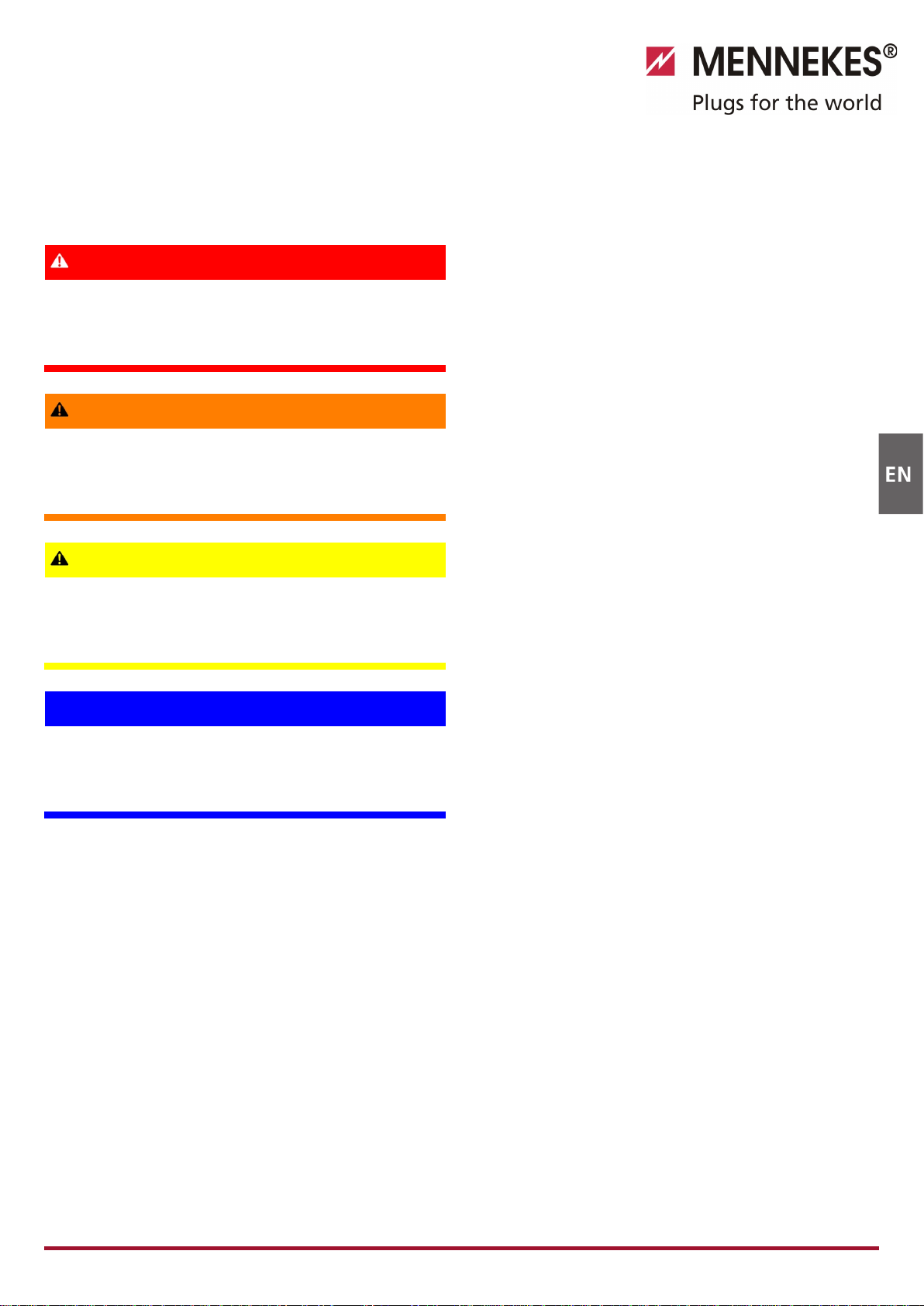
3.2 Optional equipment
Depending on the version of the charging station, the
following optional features are available:
Connector systems
Fig. 1
Depending on the version, the charging station is equipped
one of the following connector systems:
ACharging socket type 2 for use with separate charging
cable.
BPermanently connected charging cable with charging
connector type 2.
CPermanently connected charging cable with charging
connector type 1.
Wechs el ein-auf z weis palti g

6
Xtra
1)
Xtra E
2)
Xtra R
2)
Trend E
2)
Premium
1)
Premium R
2)
LED info bar
Multi-function button
Stop function (adjustable parameters,
deactivated by default)
Reset function
Testing the residual current circuit
breaker
— —
Re-activating the residual current
circuit breaker
— —
Residual current circuit breaker (RCCB)
—
—
Circuit breaker (CB)
—
—
—
—
Calibrated digital energy meter
—
Charge APP for authorising and
visualising charging processes
Statistics function over Charge APP
—
Charged amount of energy displayed on
Charge APP
—
RFID system for authorising charging
processes
— — —
1) Version for Germany
2) EU version
Wechs el ein-auf z weis palti g
3.3 Identification Plate
Fig. 2: Name plate (example)
1
Manufacturer
2
Protection class
3
Barcode
4
Supply network
connection
5
Date of manufacture
6
Part number / serial
number
7
Type
7
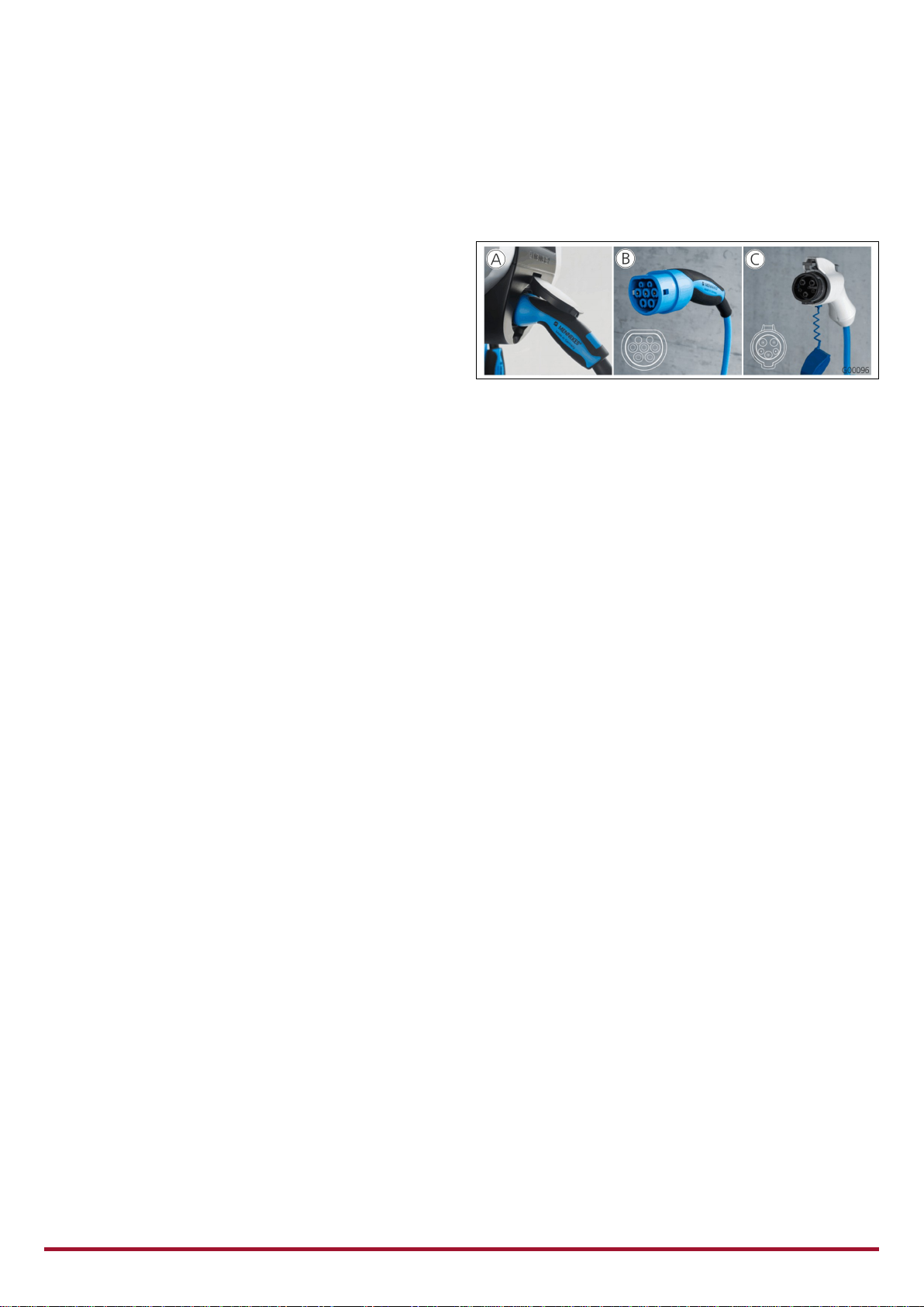
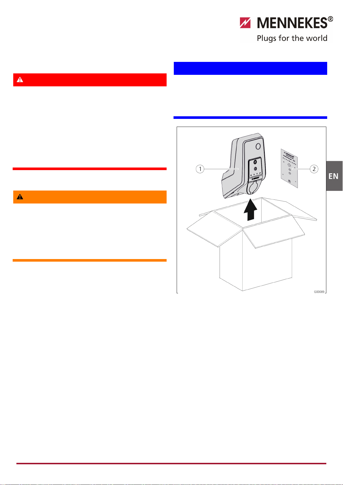
3.4 Delivery Contents
Fig. 3: Delivery contents
1
Charging station
2
RFID cards (2x master, 3x
user)1)
3
Allen key
4
Bag with installation
hardware (screws,
dowels, plugs)
5
Operation manual
6
Installation manual
7
Set-up data sheet
8
Quick guide
1) Only for versions Trend, Premium.
! CAUTION
Negative impact on the device function
Without set
-up data sheet, access to certain functions and
the configuration of the device is not possible.
Keep the set-up data sheet in a safe place for later use.
3.5 Assembly
3.5.1 Exterior view
Fig. 4: Front view (example)
1
Rear enclosure part
2
Front enclosure part
3
Window for counter
4
Front panel
5
Fastening screws for front
enclosure part
6
Predetermined breaking
point for supply line /
cable duct from below
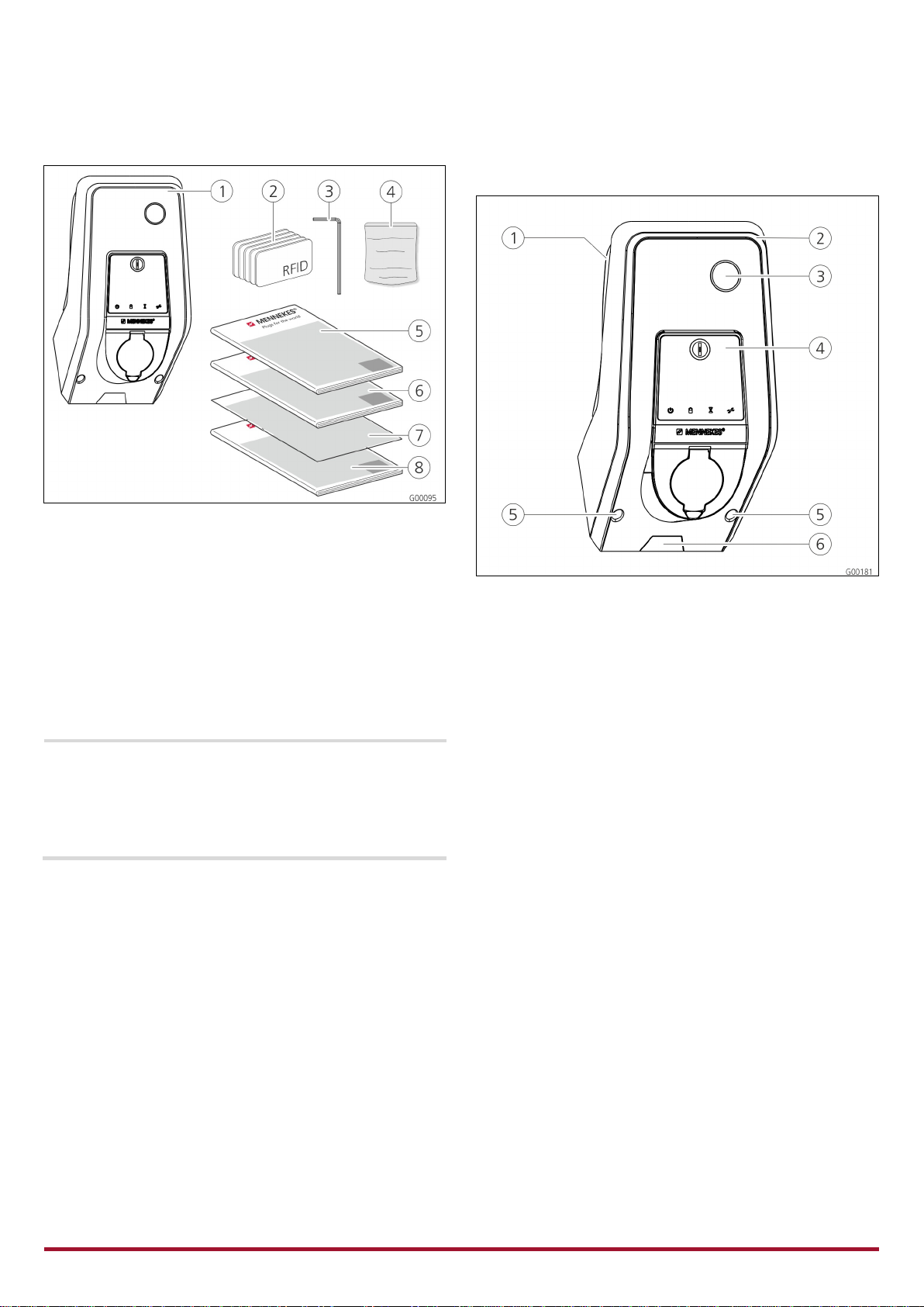
8
Fig. 5: Rear view (example)
1
Rear enclosure part
2
Fastening screws for front
enclosure part
3
Air outlet
4
Opening for cable duct
5
Fastening holes
6
Cable glands
The enclosure of the charging station has three parts and
consists of rear enclosure part, front enclosure part and the
front panel.
The front panel has to be folded down to access the internal
components. The design of the front panel depends on the
version of the charging station.
See Chapter 3.6.1 "Front panel" on page 9.
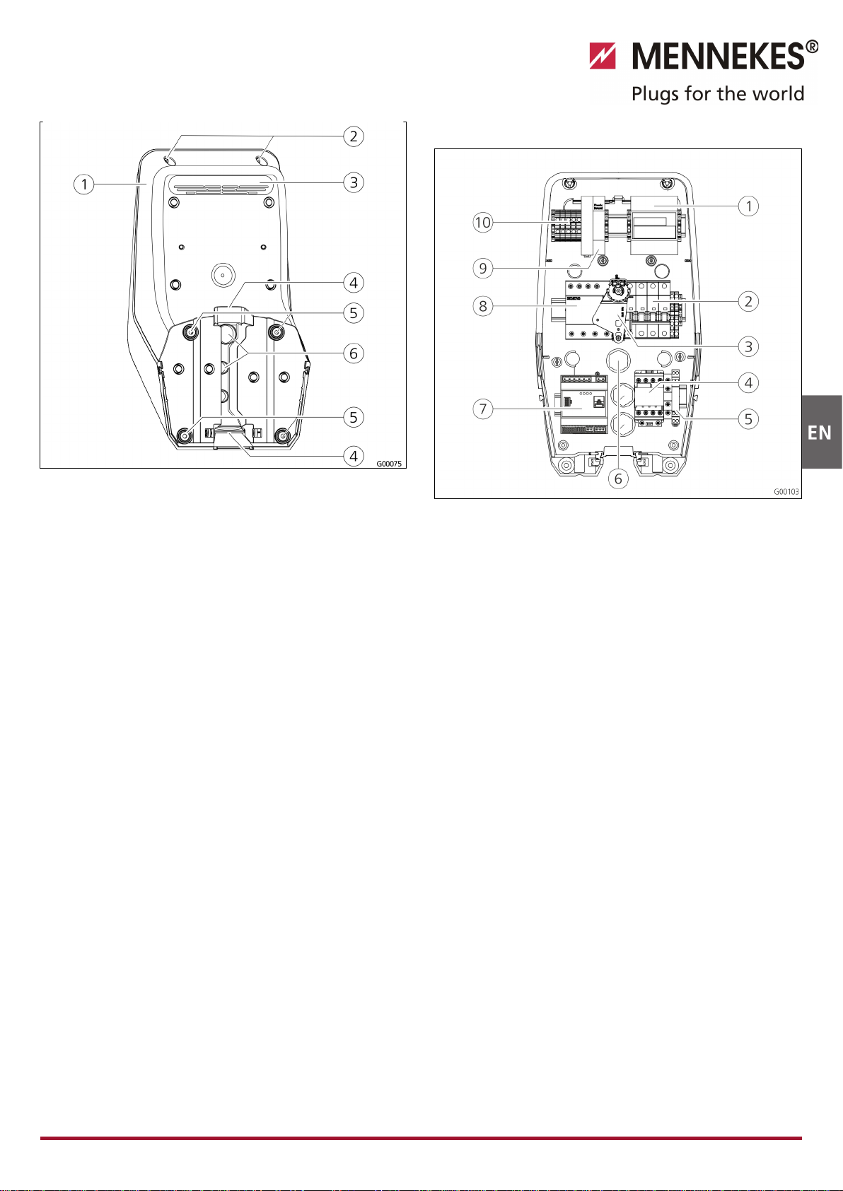
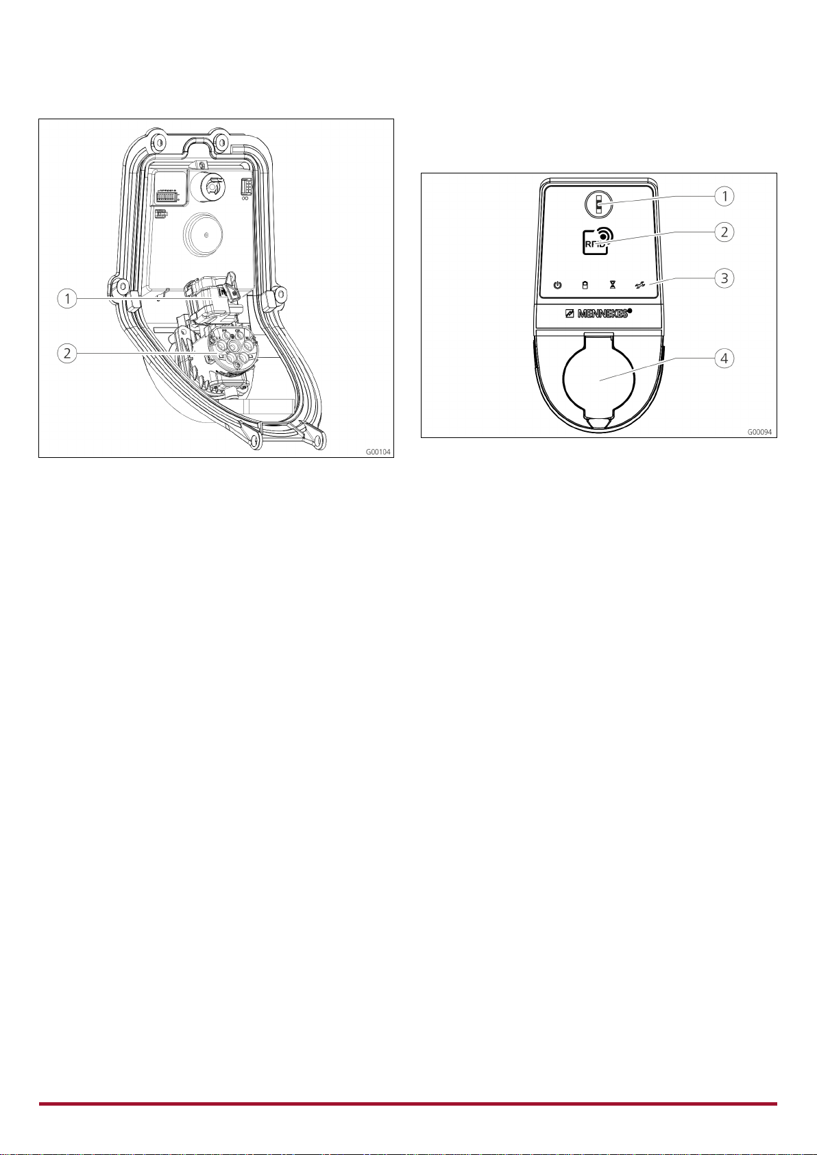
3.5.2 Interior view
Fig. 6: Interior view of rear enclosure part (example)
1
Counter
2
Circuit breaker (CB)
3
Multi-function actuator
4
Charging contactor
5
System monitoring
6
Cable glands
7
Controller (HC controller)
8
Residual current circuit
breaker (RCCB)
9
Mains adapter
j
Terminals for mains
connection
The charging station contains all required components for
controlling the charging process and communicating with
the vehicle.
The design of the components depends on the version of
the charging station.
9
Fig. 7: Interior view of front panel (example)
1
Actuator (plug interlock)
2Socket insert
The actuator interlocks the charging plug in the charging
socket during the charging process (applies only to charging
stations with charging socket Type 2).
3.6 Components
3.6.1 Front panel
Fig. 8: Front panel (example)
1
Multi-function button
2
RFID card reader1)
3LED info bar
4
Charging socket type 2
with hinged lid
1) Only for versions Premium und Trend.
The control and display elements as well as the charging
socket of the charging station are located on the front
panel.
The design of the front panel depends on the version of the
charging station.

10
3.6.2 HC controller
Fig. 9: HC controller
1
Plug strip for tariff
switching
2
Status LEDs
3
Network connector (RJ45)
4
Plug strip for power
supply 12 V DC
5
Plug strip for RS485 bus
(MENNEKES ACU)
6
Plug strip for charging
socket
7
Plug strip for S0 counter
8
Plug strip for front panel
9
Plug strip for low voltage
230 V AC
The HC controller controls the charging process in a fully
automatically and performs the following functions:
Communication with Charge APP over WLAN.
Communication with service interface over WLAN / LAN.
Analysis of the data from a connected meter.
Analysis of the monitoring system's data
Detecting the current-carrying capacity of the charging
cable with resistance coding. Unsuitable charging cables
are rejected.
It checks that the requirements for proper charging have
been met.
Querying an external signal (tariff switching).
It uses the CP contact to communicate with the vehicle.
Using a PWM signal, the charging current upper limit is
transmitted to the vehicle. The ground conductor
connection is checked at the same time.
Controlling the locking of the charging plug in the
charging socket (for devices with charging socket Type
2).
Controlling the charging contactor.
The HC controller provides five operating modes that can be
changed even during operation depending on the
configuration. The operating mode is selected over the
service interface or the MENNEKES Charge APP.
The availability of the operating modes and functions
depends on the version of the charging station and the
configuration of the charging station during the setting-
up process. When switching to operating mode "SCU",
the HC controller must be restarted.
Operating mode "Manual (Remote)"
In this operating mode, the charging process is controlled by
the Charge APP.
See table "Functional description of manual operating
mode (remote)" on page 32.
Operating mode "Time-Controlled (internal)"
In this operating mode, the charging process is controlled by
the integrated tariff-switching timer. This allows adapting
the available charging current to various main / off-peak
tariffs. For example, during an off-peak period the charging
station can charge with higher charging power than during
more expensive main tariff periods.
The valid tariff periods supplied by the electricity provider
are entered in the Charge APP and the charging station
adapts the charging current according to the periods
entered.
Updating the tariff-switching timer and changing of
daylight saving / standard time happen in connection
with the charge APP.
See table "Functional description for operating mode
time-controlled (internal)" on page 33.

11
Operating mode "External Tariff Signal"
In this operating mode, the charging process is controlled
over an external contact (such as a ripple control receiver).
In addition, the available charging current can be adapted to
various main / off-peak tariffs as in operating mode "Time-
Controlled"
See table "Functional description of operating mode
External Tariff Signal" on page 34.
Operating mode "Energy Manager"
In this operating mode, the charging process is controlled
over the SUNNY HOME MANAGER (www.SMA-Solar.com).
The charging station is connected to the SUNNY HOME
MANAGER over LAN / WLAN. Both devices must be on the
same network.
The SUNNY HOME MANAGER then controls the charging
power depending on the energy generated by the
photovoltaic system and user preferences.
See table "Functional description of operating mode
Energy Manager" on page 35.
Operating mode "SCU"
In this operating mode, the charging process is controlled by
a higher-level back-end system (such as MENNEKES E-
Mobility Control Panel).
The charging station is connected to a MENNEKES ACU over
RS485.
In operating mode SCU, control over Charge APP or
switching to other operating modes is not possible.
See table "Functional description of operating mode
SCU" on page 36.
4Technical Data
4.1 General data
3.7 kW 7.4 kW 11 kW 22 kW
Nominal voltage
230 / 400 V AC ±10 %
Nominal
frequency
50 Hz
Nominal current
16 A
32 A
16 A
32 A
Maximum back-
up fuse
according to name plate /
configuration
Charging power
Mode 3
3.7 kW 7.4 kW 11 kW 22 kW
Max. charging
current
Mode 3
16 A,
single-
phase
32 A,
single-
phase
16 A,
three-
phase
32 A,
three-
phase
Protection class IP 44 (with permanently attached
charging cable or charging socket Type
2 with shutter)
IP 54 (with charging socket Type 2)
Protection class
I
Overvoltage
category
CAT III according to EN60664-1
Dimensions
(H x W x D)
474.8 mm x 259.2 mm x 220.1 mm
Weight 5 to 8.5 kg (depending on version)
4.1.1 Maximum cable cross-sections at terminals
rigid
flexible
3.7 kW
3 x 6 mm²
3 x 4 mm²
7.4 kW
3 x 10 mm²
3 x 6 mm²
11 kW
5 x 6 mm²
5 x 4 mm²
22 kW
5 x 10 mm² 5 x 6 mm²
4.2 Ambient conditions
Ambient temperature
-25 to +40 °C
Average temperature
over 24 hours
< 35 °C
Storage temperature
-25 to +40 °C
Altitude max. 2,000 metres above
sea level
Relative humidity max. 95 % (non-
condensing)
12
5Installation
Danger
Mortal danger posed by improper installation.
There is a risk of injury for persons performing tasks for
which they are neither qualified nor have received
appropriate training.
The device may only be installed by persons who are
familiar with this task, have been instructed with
regard to the associated hazards and who possess the
necessary qualifications.
Before installing, all safety requirements must first be
met.
5.1 Choice of location
Warning
Risk due to unsuitable environmental conditions /
installation locations.
Unsuitable ambient conditions and installation locations
may lead to dangerous situations when dealing with
electricity.
Please observe the following points when selecting an
installation location:
Do not install in potentially explosive atmospheres (e.g.
gas refuelling stations).
Do not install in flood-prone areas.
Comply with local technical connection requirements
and safety rules.
For ambient conditions, see Chapter 4.2 "Ambient
conditions" on page 11.
The charging system must be protected from direct
exposure to water jets.
The mounting surface must have sufficient strength to
withstand the mechanical stresses. When mounting on
plasterboard walls they must have at least two layers.
5.2 Unpacking
Caution
Damage to the charging station by improper
handling.
Collisions and impacts may damage the charging station.
Move the charging station with utmost caution.
Use a soft base to set aside the charging station.
Fig. 10: Unpacking
Unpacking the charging station:
1. Remove the charging station 1and the drilling jig 2
from cardboard box.
2. Place the charging station on a soft base.
13
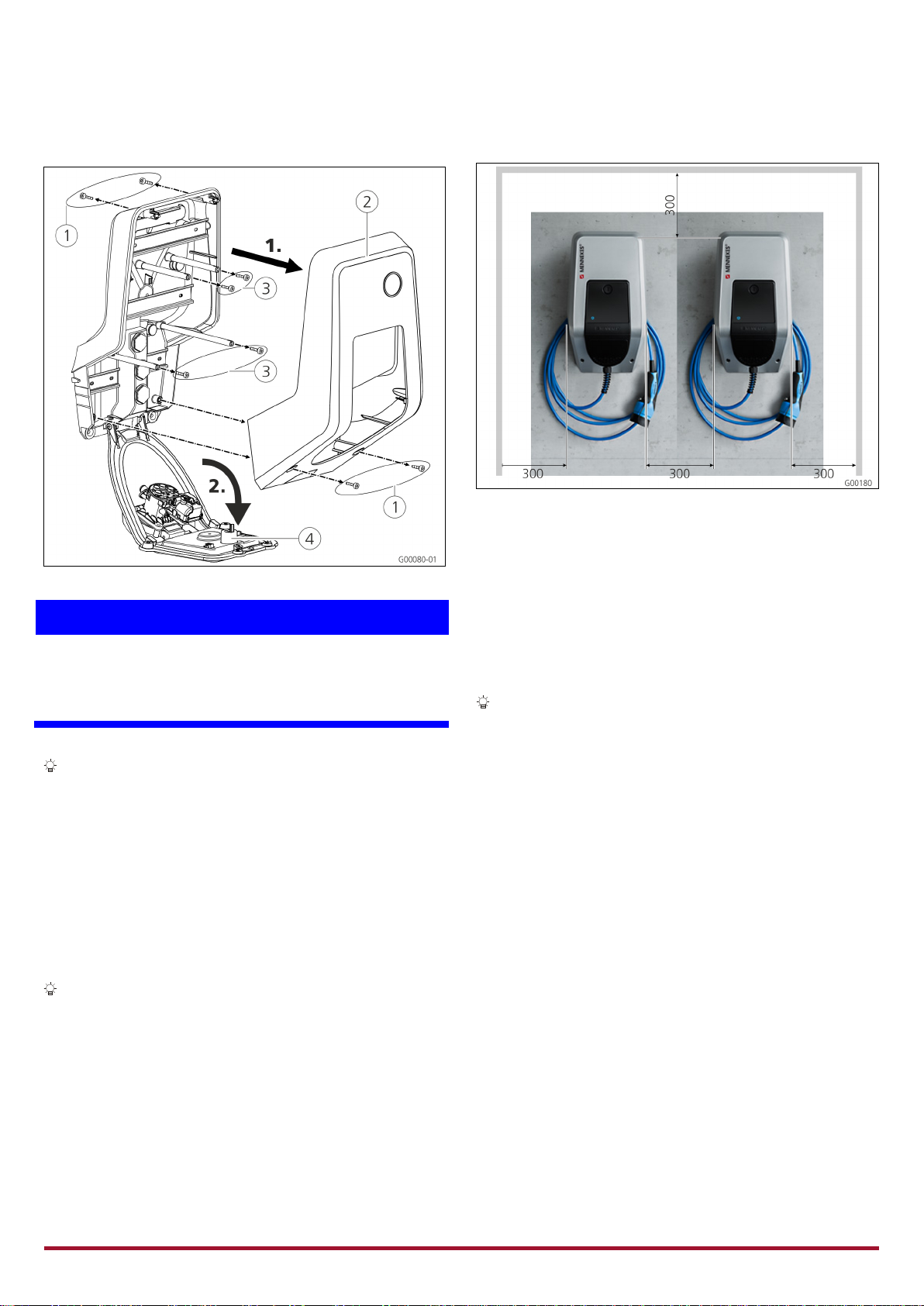
5.3 Opening the charging station
Fig. 11: Opening the charging station
Caution
Damage to the device.
Damage to the device by improper handling.
Do not use the brass bolts for attaching the front panel as
transport support or handle.
When delivered, the front enclosure part is not attached
with screws. The screws 1are stored in the enclosed
accessory bag.
Opening the charging station
1. Remove the screws 1and the front enclosure part 2.
Make sure that the screws are not lost.
2. Remove the screws 3for the front panel and fold
down the front panel 4. Make sure that the screws are
not lost.
After the installation of the charging station, the
enclosure screws on the back of the charging station
can be reached only with a shortened Allen key. The
supplied Allen key can be used.
Assem bly
5.3.1 Minimum distances
Fig. 12: Minimum distances (mm)
Maintain the specified minimum distances for unrestricted
access during operation, maintenance and repair.
5.3.2 Installing the supply cable
On-wall installation of supply cable
If supply cable or cable duct comes from below, you have to
break out the pre-cut opening in the front enclosure part.
The charging station can be placed on an on-site
installed cable duct (H 30mm x W 45mm). Suitable
recesses can be found on the back of the rear enclosure
part.
See also Fig. 13: Wall mounting.
Concealed installation of the supply cable
In a concealed installation of supply, data, and control lines,
their positions must be arranged in accordance with the
drilling jig.
14
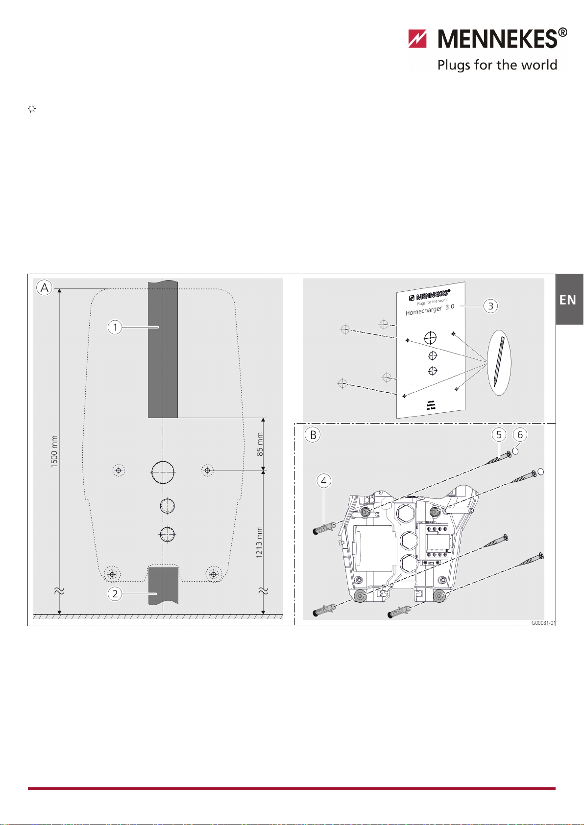
5.3.3 Installing the charger station on the wall
For installation on concrete, brick and wood walls, use
the included installation hardware.
For other surfaces, a suitable on-site mounting method must
be chosen.
MENNEKES recommends the installation of the charging
station at a height (up to the top edge of the enclosure) of
approximately 1.50 metres above the finished floor.
See also Fig. 13: Wall mounting.
1. Mark the mounting holes using the supplied drilling jig
and a spirit level.
2. Drill the holes in the wall with the diameter specified for
the selected installation hardware.
3. Route the supply cable and possibly the data and
control cables to the positions specified on the frilling
jig. A cable of approx. 40 cm cable is needed for the
electrical connection inside the charging station.
4. Open the charging station (see Chapter 5.3 "Opening
the charging station" on page 13).
5. Run the supply cable and possibly the data and control
cables through the cable glands into the charging
station.
6. Secure the charging station to the wall by using dowels
and screws.
7. Check the charger for firm and secure fit.
Wechs el ein-auf z weis palti g
Fig. 13: Wall mounting
A
Marking
1
Cable duct (for supply cable from above)
2
Cable duct (for supply cable from below)
3Drilling jig
B
Installation
4
Dowels
5
Screw
6Plug (touch guard)
Wechs el ein-auf z weis palti g

15
5.4 Electrical connection
5.4.1 Voltage supply / supply network connection
Danger
Risk of death by electric shock!
Components have voltage applied.
Contact with current conducting parts results in an electric
shock, burns or death.
When working with the electrical system, the following
points must be observed:
Disconnect device from voltage.
Secure device from being turned back on.
Ensure that no voltage is applied.
Earth and short-circuit the unit.
Cover neighbouring componets that are under voltage
and secure the danger area.
During installation, the following points must also be
observed:
The electrical installation, setting-up and maintenance
of the device may only be carried out by qualified
electricians and in compliance with the applicable
national regulations (see chapter entitled 2.4
"Qualification of Personnel" on page 4).
Before connecting the device, caution must be taken to
ensure that it is free of voltage or the appropriate
protective measures have been taken.
Note the following points when connecting to the power
supply:
Observe DIN VDE 0100 Part 530 for installation in
Germany.
Observe the applicable national / local regulations when
installing in other countries.
Ensure a clockwise rotating field for a three-phase
connection.
5.4.2 Safeguarding and personal protection
Danger
Danger to life by electric shock
Residual current circuit breakers (type B) sensitive to
universal currents may not installed behind residual
current circuit breakers (type A) sensitive to pulse currents.
Depending on the equipment package, the charging
stations are fitted with the required safety equipment
according to the following table.
Version
RCCB
type A
RCCB
type B
CB
Xtra, Premium
(3.7
kW / 7.4 kW, single-
phase)
—
Xtra, Premium
(11 kW / 22 kW, three
-
phase)
—
Xtra E, Trend E
(3.7
kW / 7.4 kW, single-
phase)
— — —
Xtra E, Trend E
(11
kW / 22 kW, three-
phase)
— — —
Xtra R, Premium R
(3.7
kW / 7.4 kW, single-
phase)
— —
Xtra R, Premium R
(11 kW / 22 kW, t
hree-
phase)
— —
Note the following points when connecting the charging
station:
Each charging station must be connected using a
separate residual current circuit breaker (residual current
circuit breaker type A for single-phase versions, residual
current circuit breaker type B for three-phase versions).
No other circuits may be connected to this residual
current circuit breaker.
For versions Xtra E and Trend E, the residual current
circuit breaker (RCCB) must be provided on site.
For versions Xtra E, Xtra R, Trend E, Premium E and
Premium R, the circuit breaker (CB) must be provided on
site.

16
Design of the on-site circuit breaker
Danger
Fire hazard due to device overload.
Fire hazard due to device overload in case of wrong
design of the on-site circuit breaker.
The nominal current of the selected circuit breaker must
not exceed the specifications on the nameplate.
The EU versions of the devices (Xtra E, Xtra R, Trend E,
Premium E und Premium R) are supplied without integrated
circuit breakers. The circuit breakers must be scaled
according to the specifications on the name plate, the
required charging power, the supply line (line length, cable
cross-section) to the charging station and national
regulations.
5.4.3 Terminals
Fig. 14: Terminals for the supply line (example)
Connect the supply line:
1. Strip the supply cable over a length of 370 mm and
remove the core insulation over a length of 12 mm.
2. Connect the cores 2of the supply cable to the
terminal block 1according to the circuit diagram. The
protective earth conductor (PE) must be longer than all
other conductors!
3. Check that the individual cores are properly connected
and that the screws are tightened.

17
5.4.4 LAN connection
The charging station can be integrated into a home network
wirelessly over WLAN or wired over an Ethernet cable (RJ45).
Wireless networking
If the charging station is within range of the wireless
network, no additional wiring is required.
For more information on setting up the WLAN connection,
see the Chapter 6.2.2 "WLAN connection" on page 19.
Wired networking
If the charging station should be integrated into the home
network through Ethernet, a suitable network cable with
RJ45 plug must be routed to the charging station.
The network cable must have sufficient dielectric strength,
and be suitable for common routing with live conductors.
MENNEKES recommends using Ethernet cables type Cat 5e
or higher.
Fig. 15: Connecting the network cable
Connect the network cable:
1. Route the network cable into the charging station.
Make sure that the bending radius of the network cable
does not exceed the specified permissible value and the
network cable is not kinked.
2. Connect the plug 2of the network cable to the
network socket of the HC controller 1.
For more information on setting up the Ethernet connection,
see the Chapter 6.2 "Setting up the network connection"
on page 19.
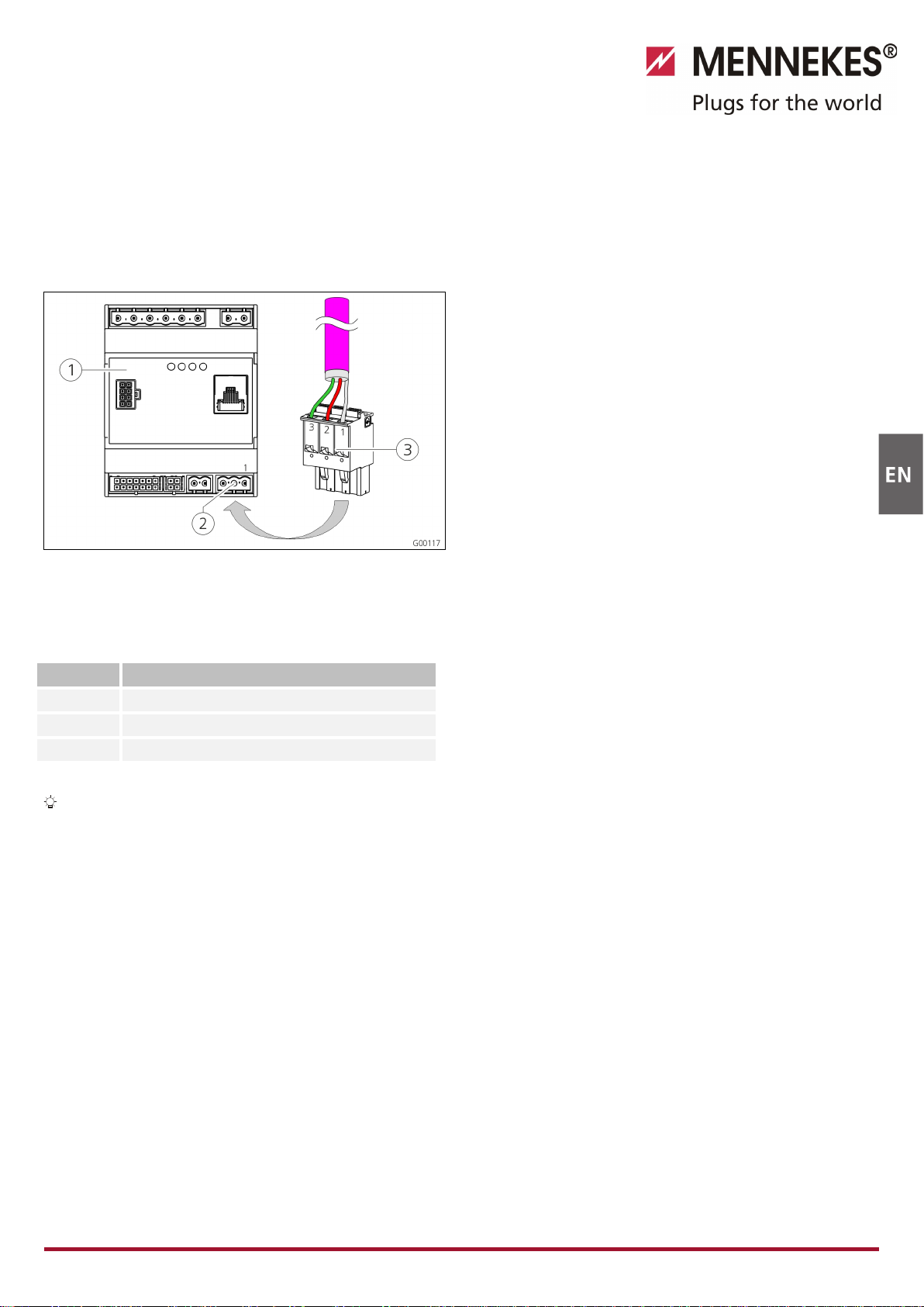
5.4.5 Tariff-switching signal
For operating the charging station in mode "external tariff
signal", a connection to, for example, a ripple control
receiver is required.
The tariff-switching signal is connected to the HC controller
with a connector.
If the off-peak tariff is active, the tariff-switching signal
must be present at the input.
If the main tariff is active, no tariff-switching signal must
be present at the input.
Fig. 16: Connecting the tariff-switching signal
1
HC controller
2
Plug strip for tariff-switching signal
3Plug
Terminals Description
1 (N) Neutral conductor for tariff-switching signal
230 V AC
2 (L)
Phase for tariff-switching signal 230 V AC
Connect the tariff-switching signal:
1. Route the control line into the charging station.
2. Connect the control line as shown to the plug of the
input.
3. Insert the plug into the appropriate plug strip at the HC
controller.
When connecting the tariff-switching signal to an
external voltage source, a note conforming to national
regulations must be attached (e.g. in form of a sticker).
For further information on tariff switching, refer to the table
"Functional description of operating mode External Tariff
Signal" on page 34.
18
5.4.6 RS485 bus
If a higher-level back-end system (e.g. MENNEKES E-
Mobility Control Panel) should control the charging process,
the charging station must be connected to a MENNEKES
ACU over RS485 bus. The bus cable is connected to the HC
controller with a connector.
Fig. 17: Connecting the RS485 bus
1
HC controller
2
Plug strip for RS485 bus
3
Plug
Terminal Description
1 (C)
Reference level (shielding, see note!)
2 (B)
Bus signal B
3 (A)
Bus signal A
To avoid balancing currents, the shielding of the bus
cable may be earthed only on one side. This is usually
done at the ACU or E-Mobility Control Panel.
Connect the RS485 bus:
1. Route the control line into the charging station.
2. Strip the bus line and bare the shielding.
3. Connect the shielding to the terminal 1 of the plug.
4. Connect the single cores to terminals 2 and 3 (e.g. for
Siemens Profibus communication: green wire to
terminal 3, red wire to terminal 2).
MENNEKES recommends the following cables for the RS485
bus:
For installation in the ground: Siemens PROFIBUS line,
underground cable 6XV1830-3FH10 (manufacturer EAN
4019169400428).
For installation without mechanical stress: Siemens
PROFIBUS line 6XV1830-0EH10 (manufacturer EAN
4019169400312).
When using the recommended cables, trouble free
operation at bus lengths up to 300 metres can be expected.

19
6Commissioning
Warning
Danger due to incorrect commissioning!
There is an increased risk of injury for persons performing
tasks for which they are neither qualified nor have received
appropriate instruction.
The device may only be installed by persons who are
familiar with this task, have been instructed with
regard to the associated hazards and who possess the
necessary qualifications.
Before installing, all safety requirements must first be
met.
6.1 Turning on the charging station
To turn on the charging station, proceed as follows:
1. Make sure that all protective devices (RCCBs and CBs) in
the charging station are turned on.
2. Turn on the power supply (back-up fuses, residual
current circuit breaker or circuit breaker).
3. Check the supply voltage at the charging station for
clockwise rotating field (see Chapter 9.3 "System
monitoring" on page 44).
The LED on the power supply unit will light.
The corresponding symbol on the LED info bar indicates
the operational readiness of the charging station.
6.2 Setting up the network connection
6.2.1 LAN connection (Ethernet)
If the charging station has been integrated into the home
network over a LAN cable (Ethernet, RJ45), no further
configuration on the network connection is usually
necessary.
The charging station receives the IP address over the DHCP
function of the customer's Internet router.
6.2.2 WLAN connection
When delivered, the internal WLAN module operates in
access point mode. This means that the charging station
provides a separate WLAN, ensuring that a connection of
the Charge APP to the charging station is possible without
on-site WLAN.
The access point mode is always active when the
charging station has not yet been integrated into a
WLAN or WLAN is not available.
6.3 Configuration of the charging station
Functions and operating modes are configured with the
service interface in the Internet browser of the charging
station. The service interface of the charging station is
accessible over LAN or WLAN.
Requirements for Internet browsers:
JavaScript activated
Microsoft Internet Explorer 11 or higher
Mozilla Firefox version 30 or higher
Google Chrome version 35 or higher
Opera version 20 or higher
Current smart phone browsers (iOS, Android)
6.3.1.1 Access over WLAN
In access point mode, the service interface is accessible
over http://172.31.0.1:25000.
In a home network, the charging station receives the IP
address over the DHCP function of the customer's
Internet router. You can retrieve the IP address with the
web interface of the internet router or with an app such
as the free of charge network scanner Fing.
The address looks as follows: http://AMTRONIP:25000
(e.g. http://192.168.0.20:25000).
Access is the same as for the direct connection.
6.3.2 Access over LAN
The charging station receives the IP address over the
DHCP function of the customer's Internet router. You
can retrieve the IP address over web interface of the
Internet router.
If DHCP is not available, access is possible over LAN with
IP address http://192.168.0.100:25000, network
mask 255.255.255.0.
A direct cable connection without DHCP is possible.
Other manuals for AMTRON Xtra
1
This manual suits for next models
5
Table of contents
Other Mennekes Automobile Accessories manuals


Popular Automobile Accessories manuals by other brands


ULTIMATE SPEED
ULTIMATE SPEED 279746 Assembly and Safety Advice

SSV Works
SSV Works DF-F65 manual

ULTIMATE SPEED
ULTIMATE SPEED CARBON Assembly and Safety Advice

Witter
Witter F174 Fitting instructions

WeatherTech
WeatherTech No-Drill installation instructions

TAUBENREUTHER
TAUBENREUTHER 1-336050 Installation instruction