EROAD CoreHub Xtreme User manual

EROAD
EROAD CoreHub Xtreme
Install Guide
Thermo King, AUS, NZL
Technical support
USA 1-855-503-7623 [email protected]
AUS 1800 437 623 [email protected]
NZL 0800 437 623 [email protected]

Parts & equipment
CoreHub Xtreme (the ‘unit’)
Trailer & reefer Smart harness
External antenna
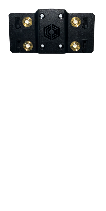
Bracket
Zip ties, screws

•
•
•
•
•
•
1.
2.
3.
Required tools
Socket/ Spanner set
Side cutters
Impact driver and hex bits
18/20ga butt splice crimping tool
Propane torch
Platform to safely reach the top of the reefer
Pre-prep
Start the reefer to ensure it’s working with no
console alarms.
Ensure the reefer has its iBOX/REB/Bluebox 1
or 2 firmware updated.
Use the Safety Lockout Procedure -
disconnect any AC power source and battery
NEGATIVE.
A ladder is fine for heights up to 2 m (7
ft) but should not be considered safe
for reaching the top of a reefer. Where
possible, use a scissor-lift, forklift
basket, or similar stable, load-bearing
platform.

•
Mount the unit
For SR4 units, mount the unit to the front of the
trailer above the battery.
Bracket

Precedent
•
•
Legacy units
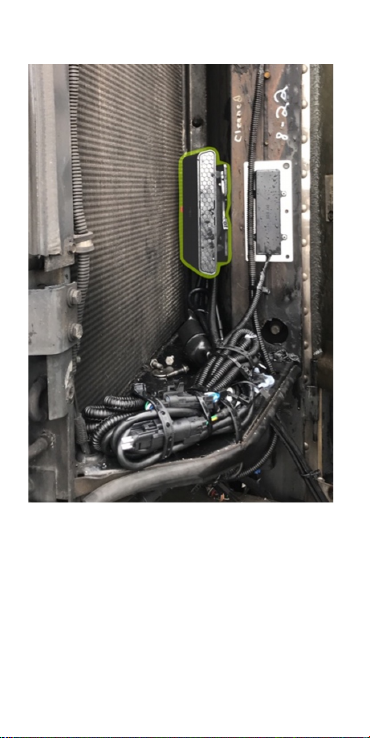
For legacy units (SR3 and before), mount the
unit vertically on the upper half of the reefer
next to the condenser inflow (above the
display).
Keep the unit and cables away from hot or
moving parts, and high voltage lines (usually
colored orange).
•
•
Mount the antenna
Attach the antenna to the top of the reefer or
the side front of the trailer. It should directly
see the sky.
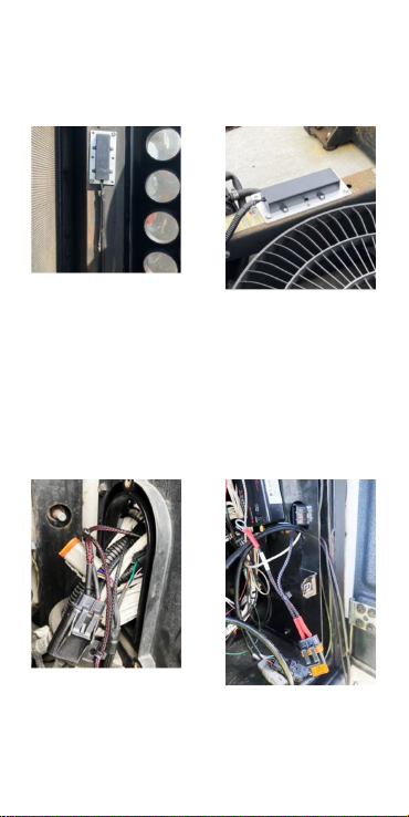
Run the cables into the controller
enclosure
Open the Precedent control compartment
cover. Unscrew the cable cover to push the
cables through to reach the power and data
connections. In legacy models, remove the fuse
cap to push the cables through a round hole.

1.
2.
1.
2.
Plug the unit into the
reefer 3rd party port
The unit’s harness has connectors for reefer
data and fuel sensor. It plugs into the 3rd
party communications port located inside the
reefer controller module.
Depending on the reefer type and readiness
for telematics it may be necessary to do
additional work to add this port to the reefer.
This is described in additional documentation
covering legacy, I-Box, REB and Blue-Box
connections.
Connect reefer power
Connect the BLACK ground ring to the “CH”
stud on the reefer controller board.
Connect the RED power ring at the “2” stud on
the reefer controller board.

1.
2.
Reefer on; look for a
solid red light
Reconnect the battery.
Use the displayed table to troubleshoot the
unit’s status.
Color Flash Desc
Pink Solid Bootup
Blue Solid Starting Services
Green Solid /Ignition
On
Disconnected from
Cloud
Red Flashing /
Ignition Off
Connecting to Cloud
Red Solid /Ignition
Off
Connected to Cloud
Orange Flashing /
Ignition On
Connecting to Cloud
Orange Solid /Ignition
On
Connected to Cloud

1.
2.
3.
4.
5.
6.
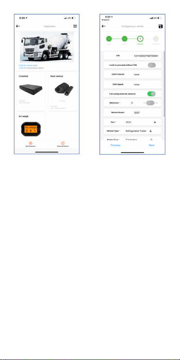
Use the Installer app to
commission the unit & wireless
sensors
Scan the QR code to download or search for
Unit in Google Play or Apple’s App Store.
Log in to the app using your Core360
credentials.
Turn on the reefer and verify that the unit’s
status LED is solid red and that you are within
5 m of it.
Select Install from the home screen.
Use the Unit QR code to identify the unit to the
app.
Enter the trailer and reefer information.
•
•
•
•
Add sensors one at a time by scanning their QR
codes. Each sensor has diagnostics.
Photo verification
Installers are encouraged to photo-document their
work to assist in supporting work order
documents.Any digital camera may be used for 2
or 3 images per site, but images must:
Show the device clearly, mounted in place,
oriented appropriately.
Show connections and wiring secure and tidily
managed.
Indicate the environment in which the device is
installed (its position in the cab, or on the
asset).
You may also wish to note the vehicle make/
model for future reference.

Health and safety
There are no user-serviceable parts.
This device was designed to track land-based
Assets that may be subjected to rain, light
impacts and general mud and dust. Installation in
or on water-borne equipment is not
recommended and is not covered by EROAD's
warranty.
This device is factory-sealed; tampering will void
the warranty.
Before installing EROAD equipment in a vehicle
you must be, in Australia, an approved EROAD
installer and, in New Zealand, an accredited
EROAD installer. EROAD expects installers and
contractors to understand and follow all relevant
health and safety regulatory requirements.
The installer must wear appropriate Personal
Protective Equipment (PPE) for the install risk and
customer requirements. PPE may include safety
glasses, safety shoes, work gloves, hard hat, high
visibility vest, sun cream, sun hat and coveralls.
You must understand and comply with the safety
requirements of customers or third parties.
Photos are evidence of a
compliant install. They protect
EROAD’s and the Installer’s
liability, should a future 3rd party
or incident affect compliance
integrity.

Avoid fitting EROAD equipment in locations that
could impede or cause injury to people. This
includes potential head strike zones on the
windshield or dashboard, airbag deployment
locations, seatbelts, and other safety-relevant
devices.
The vehicle must be parked and level, with the
parking brake engaged.
Before installation, check that other safety-
relevant equipment is working properly and report
any issues to the customer.
Before installers are permitted to work under or
around suspended equipment – held aloft with
slings, hoists, or jacks – ensure the equipment is
secured to prevent collapse or falls.
Avoid running cables close to heat sources, sharp
edges, obstacles or safety-relevant devices.
After installation, check that all other safety-
relevant equipment continues to work properly.
While EROAD hardware is comprehensively tested
against corrosion and ingress, devices are not
invulnerable to water, fire or impact damage. Do
not subject EROAD devices to extreme heat, high-
pressure water force or other intense physical
forces.
Protect this device and other EROAD devices from
extreme temperatures. Operating temperatures
for the equipment related to this guide are found
in the specifications page.
Installers must ensure they fully understand these
instructions before installing an EROAD-supported
device and immediately seek advice from a
Regional Installation Manager on any matter that
is not understood.

Legal
The legislation and rules concerning the
installation and operation of GPS driver aids vary.
You are required to be familiar with the applicable
laws of the jurisdiction(s) in which the vehicle will
be operated. This includes the rules governing
installation of GPS driver aids, distracted driving
legislation and other road rules.
It is your and your vehicle driver’s sole
responsibility to install and use the device in a
manner that complies with the law and will not
cause accidents, personal injury or property
damage. To the fullest extent permitted by law,
EROAD disclaims all liability and excludes all
warranties for installation or use of this device in
a way that may violate such laws and regulations.
As EROAD is continuously improving its products,
EROAD may make changes to this device at any
time, which may not be reflected in this
document. Please contact your nearest EROAD
office if you require any further assistance.
If you think that the installation of this device may
have caused your vehicle’s performance to be
impeded, please contact EROAD Technical
Support immediately to resolve the issue. EROAD
is not liable for any costs or expenses incurred by
engaging a third party to repair the fault without
EROAD’s prior consent.

1.
2.
3.
4.
1.
2.
Addendum
Migrating from a TMU to Xtreme
Unplug the TMU unit from all cabling.
Take photos of the installation beyond this
step. Record/confirm the serial number of the
TMU before moving on.
Except for the fuel sensor and its cabling,
remove the antenna and any connected TMU-
related hardware (harnesses, door sensors,
etc).
If other equipment was removed as part of the
de-install, fill holes with appropriate
grommets, and weatherproof with silicone.
Mount the Xtreme
Follow the steps detailed in this guide, with the
following call-outs:
If using the same TMU locations for the
Xtreme and its antenna, (re-use holes, braces/
supports, changes in reefer layout/
appropriateness, gotchas)
For some customers, a new wireless door
sensor will need to be installed.

Specifications
Cellular 4G LTE
WiFi 2.4 & 5 GHz 802.11 a/b/g/n, 150
Mbps
Bluetooth Classic+BLE 4.2
GPS GPS, BEIDOU, GLONASS, Galileo
Power 12 V, 0.5 A
24 V, 0.25 A
Int. Battery Lion rechargeable, or
Li-hybrid Supercap (Optional)
Dimensions 160 x 90 x 25 mm (6.3 x 3.5 x 1
in)
250–400 g (0.5–0.8 lb)
Temperature -40 — +70°C
IP Rating IP66K

Pinout
# Function # Function
1 RX2 (normally debug) 11 ADIO 5
2 TX2 (normally debug) 12 ADIO 4
3 RX1 (shared J1708) 13 ADIO 3
4 TX1 (shared J1708) 14 ADIO 2
5 CAN LOW 15 ADIO 1
6 CAN HIGH 16 GND
7 1708-/ CAN1 LOW 17 1-Wire
8 1708+/ CAN1 HIGH 18 EXT 5/ 5V SW
9-VIN/ Solar Panel- 19 EX 12/ 12V
SW
10 +VIN 20 Solar Panel+
Other manuals for CoreHub Xtreme
1
Table of contents
Other EROAD Automobile Accessories manuals


