AutoCrib C User manual

AUTO
CRIB
16812 Gothard Street, Huntington Beach, CA 92647
Phone: (714) 274-0400 Fax: (714) 274-0399
RoboCrib Operations Manual
Model C Last Revision 6/20/2003
1

AUTO
CRIB
Section I. Initial Placement & Installation
Set up …………..…………………………………...……………………………………………………….4
i. Initial Placement……………………………………………………………………………….4
ii. Installation……………………………………………………………………………………..4
Section II: Technical Specifications:
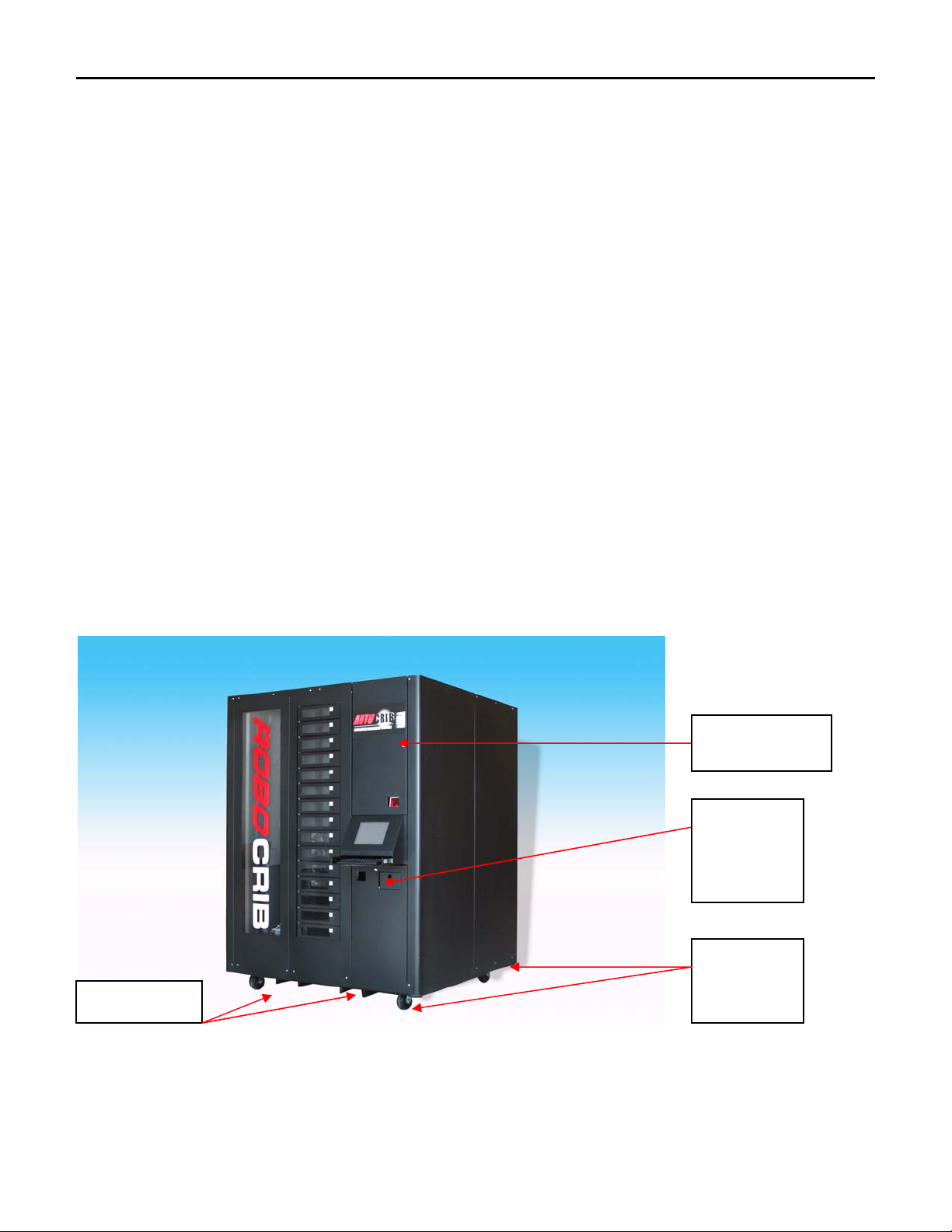
RoboCrib’s External Parts..……………………………………….……………………….………………..10
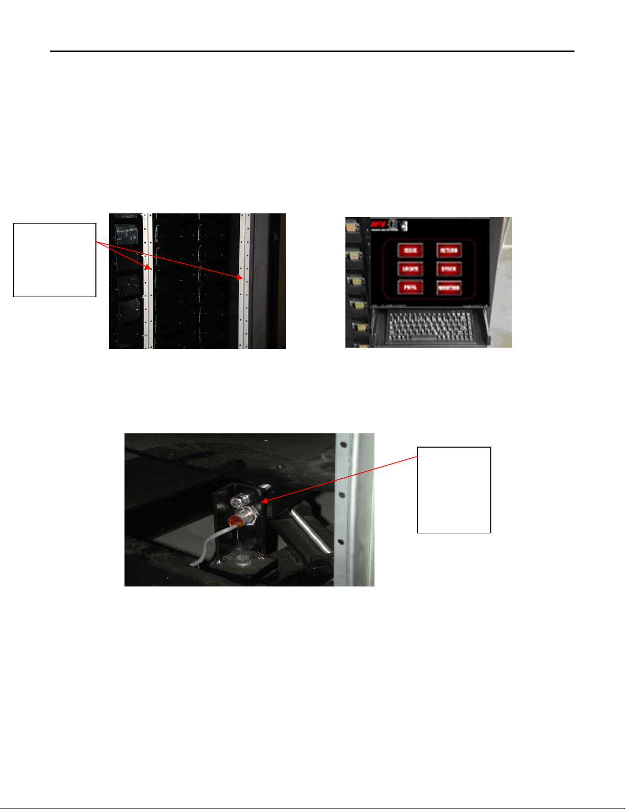
Drive System …………………………………………… …….…………………………………………..11
Posts, Hex Shafts Mounting Arms, Tray Assemblies ………….………………..…………………………11
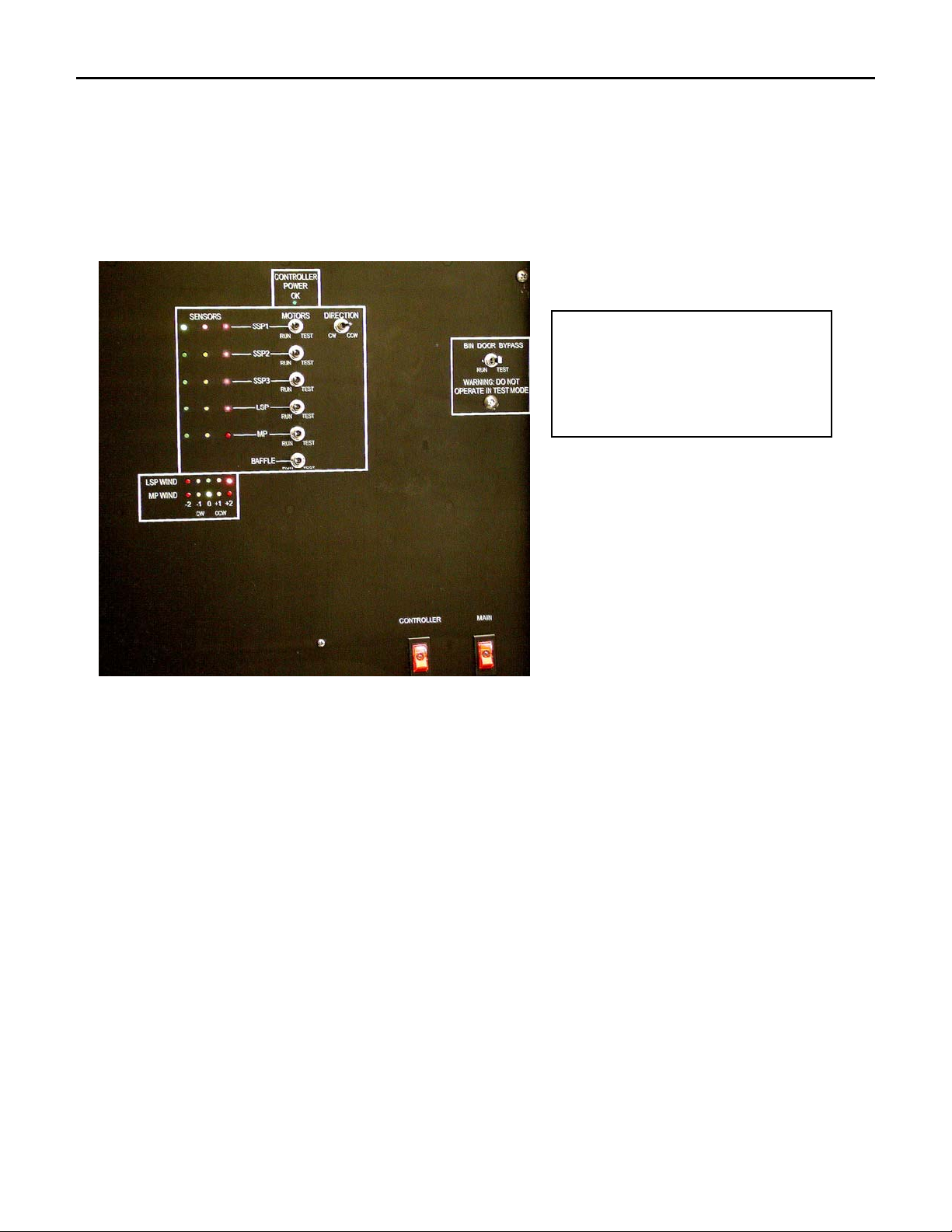
Calibration and Alignment……………………………………………………………………………..…...12
Bin Doors and Baffle Assemblies..……………………………………………………………………….....12
Wind Protection……………………………………………………………………………………………..12
Section III: Commonly Performed Procedures
Hardware ……………………………………………………………………………………………………14
i. Perform a calibration sequence…………….…………………………………………….…...14
ii. Exiting RoboCrib Software…………………………………………………………………...14
iii. Proper Loading Procedure……………………………………………………………………14
iv. Removing Walls of RoboCrib………………………………………………………………..15
v. Maintenance Mode……………………………………………………………………………15
vi. Using the MTTTY Editor……………………...……………………………………………..15
RoboCrib Software Operations
i. Restocking using the Automatic Bin Method……………...….…….………………………..16
ii. Restocking Using the Automatic Tag Method………………………………………………..16
iii. Restocking Using the Manual Method………………………………………………………..17
iv. Perform a Physical Count on One Bin………………………………………………………..17
v. Perform a Physical Count on All Bins………………………………………………………..17
vi. Issue an Item from the RoboCrib……………………………………………………………..17
vii. Return an Item to the RoboCrib………………………………………………………………17
viii. Locate an Item in the RoboCrib or anywhere in the AutoCrib system……………………….18
ix. Troubleshooting Using the “Maintain” Function……………………………………………..18
Section IV: Trouble Shooting Common Problems
Install or Replace a Touch Screen.………………………………………………………………………….19
System will not Calibrate……………………………………………………………………………………19
System will not initiate Calibration…………………………………………………………………………19
RoboCrib will not Dispense…………………………………………………………………………………19
Manual switches are not Operational (Need to get to product)……………………………………………..19
Bin Door will not open..…………………………………………………………………………………….20
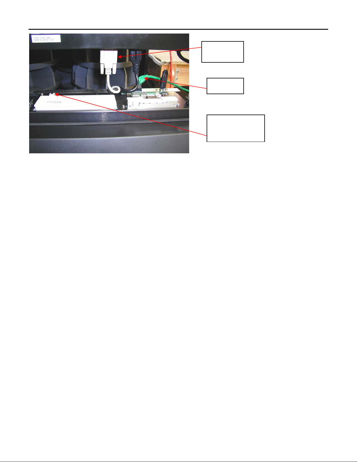
Replacement of Controller…………………………………………………………………………………..20
Chain Needs to be Remounted because it has Broken or Come off of the Gears…..………………………20
Section V: Preventative Maintenance
Cleaning Exterior surfaces…….………………………………………………………………………..…..21
Hardware……………………..……………………………………………………………………..………21
Appendix I
RoboCrib Controller Commands……………………………………………………………………………23
Appendix II
Explanation of Errors on a RoboCrib……………………………………………………………………….24
2

AUTO
CRIB
Tools Needed for Installation
•Outlet Tester (can be purchased at Radio Shack)
•Open End Wrench
o(2) 9/16: Used to remove the main platter locking bolt during installation.
o(1) 3 /4: Used to install the leveling feet during installation.
o(1) 3/8: Used to tighten the nyloc bolts on the RoboCrib PC.
•Level
•Cordless Drill: Used to uncrate the RoboCrib.
•Socket Driver (7/16): Used to remove the bolts on the panels of the RoboCrib.
•#2 Phillips Screwdriver
•Pin-In-Hex Screwdriver (included): Used to remove the security bolts on the panels of the
RoboCrib.
•Flat Head Screwdriver
3

AUTO
CRIB
Section 1 Initial Placement & Installation
I. Initial Placement
1. Upon Arrival, check the following:
a. Damage to the pallet and/or wrapping
b. Status of “TipNTell”
c. Note any damage or irregularities on shipping document
d. DO NOT SIGN FOR SHIPMENT IF ANY DAMAGE HAS OCCURRED.
REFUSE THE SHIPMENT.
2. Uncrate the machine
a. Use a cordless drill with a #2 Phillips head bit.
b. Retain the screws and crate in case there is damage to the machine.
3. Use a forklift to place the RoboCrib and pallet near the final location.
4. Undo the hold-down straps and lift RoboCrib from the pallet with the forklift
a. Make sure the forks of the forklift are inserted properly into the fork points on the
frame. Do not lift on the Main platter. It is important that the feet of the forklift are
completely inserted into the fork points.
b. Unwrap the unit and roll the RoboCrib to its set-up location
c. Return the pallet and straps to AutoCrib, Inc for credit, or store for future use.
II. Installation
1. Locate the keys which are attached to the Z channel with a zip tie.
2. Unlock the access door and return bin.
3. Remove the pin-in-hex driver and leveling feet from the return bin.
Access Door and
Service Panel
Return Bin,
Unlock and
retrieve
needed items
Install
Leveling feet
here.
Fork Points
4. Install the leveling feet
a. Use a forklift to lift the RoboCrib off the ground.
b. Install feet into the threaded plates in each corner.
4

AUTO
CRIB
c. Place the RoboCrib in its final location and adjust the nuts, using a ¾” open end
wrench, to level the machine. Use the level to make sure the RoboCrib is level on each
side. Lock the nuts in place.
5. Tighten the cap of the wiring harness at the top of the RoboCrib.
Do not move RoboCrib platters while Tighten the wiring harness on top of RoboCrib.
the wiring harness is not attached!
6. Remove the Right Front wall section and the Bin Door cover panel. (Use the Pin-In-Hex
driver to remove the screws).
Remove
screws using
the pin-in-hex
screwdriver
and 7/16
socket driver.
Remove these
panels
Keys to RoboCrib
are connected to Z
channel
7. Lift up on panels to disengage the tabs located on edges and pull out on the panel to
remove it.
8. Remove display assembly from box and prepare for the installation.
a. Note: the keypad drawer slides in and out freely. Take care to handle Display
Assembly securely.
b. Remove Display Assembly from the shipping box and remove the wing nuts from the
studs on each side.
c. Align the studs with the corresponding holes in the z-channel rack mounts.
5

AUTO
CRIB
d. The Display Assembly fits below the power panel and above the return tray assembly.
e. Install the studs through the holes, attach, and tighten the 2 extended wing nuts and 2
nylocks from the backside. Install the extended wing nuts on the right of the computer
(while looking at the back of the PC). Install the nylocks on the left of the computer
using a 3/8 open end wrench.
f. Attach the DB9 cable and AC plug to the outlets located on the bottom of the power
panel.
g. Attach the Cat5 cable from the NIC card located at the top of the Display Assembly to
the hub provided by AutoCrib, Inc.
Mount display
Studs In Z
channel holes
here.
9. Remove main platter locking bolt
a. Bolt is located on the sensor bracket below bin door #1.
Remove bolt
before using
machine
using the 2 –
9/16 open end
wrenches.
b. Loosen the lock nuts and unscrew the bolt using two 9/16 wrenches.
c. Retain the bolt and nuts for possible future use.
Note: This bolt is inserted horizontally through the top of the bracket and into one of the radial arms on the main
platter. Do NOT loosen the bracket-mounting bolt, which holds the bracket down on the frame.
10. Attach power and network services
a. Uncoil the power cord and route it through the bottom of the frame.
b. Attach power cord to a standard UPS (provided with the system) to a 120 VAC power
outlet – (max usage 4 Amps).
6

AUTO
CRIB
c. Use a tester to ensure the power outlet is correctly grounded. These types of tester are
available at Radio Shack.
d. Attach the DB9 cable and AC plug to the outlets located on the bottom of the control
panel.
e. Route the CAT 5 cable into the machine along the same path as the power cord.
f. Attach the CAT 5 cable from the NIC card located at the top of the Display Assembly
to the hub provided by AutoCrib, Inc.
g. Turn the Main power switch ON. Make sure the switch lights up.
h. Turn the Controller power switch ON. Make sure the green “OK” LED is lit.
i. Replace the Return Bin assembly and lock it into place.
11. Check platter actuation
Note: ENSURE THAT THE MAIN PLATTER LOCKING BOLT IS REMOVED (see #9 above), AND THAT THE
ROTATION AREA IS CLEAR!
a. Test each motor clockwise (CW) and counter-clockwise (CCW) for a few seconds. In
order to test each motor, you must hold the Motor switch at the Test position and
position the Direction switch in either the CW or CCW position.
b. As each Motor switch is actuated, the appropriate platter should turn, and the sensor
lights should blink. While testing each motor, please note how the platters should react
to the movement.
i. Main: Main Platter – the entire internal array will rotate
ii. LSP: Large Sub Platter – 3 individual and 3 groups of 3 tray assemblies
will rotate
iii. SS3,2,1: Small SubPlatters - Individual tray assemblies in groups of 3
will rotate
c. Test the door baffle by positioning the Baffle switch into the test position and the
Direction switch in either the CW or CCW position.
d. Test each door (The panel must be removed to be able to test the doors)
i. Look at each door to make sure there is an equal amount of space
between the top and bottom of the door.
ii. Pull each door switch to the right.
The door should open with ease and the “open door” indicator light
should illuminate until the door has been closed.
To actuate the
solenoid, pull the “L”
shaped, silver door
latch to the right.
iii. Due to movement during shipment, the alignment of the doors may have
shifted. If a door is not opening with ease, adjustments of the door will
be necessary to ensure free operation.
7

AUTO
CRIB
1. Swing the door back and forth to loosen the spring
2. Look to see if the plunger is aligned with the door latch. If the
alignment is off, adjust the door up or down depending on how
the door shifted during shipment.
3. While the doors are closed, there should be an equal amount of
space between the top and bottom of each door.
SWITCH DEFINITIONS
MP = MAIN PLATTER
LSP = LARGE SUB PLATTER
SSP3 = SMALL SUBPLATTER #3
SSP2 = SMALL SUB PLATTER #2
SSP1 = SMALL SUB PLATTER #1
9. Assuming this is a master RoboCrib, the Management Station and RoboCrib have been pre-
configured for a peer-to-peer network. Therefore, it is important to complete the setup of
the management station before starting the Robocrib computer.
a. Locate the “Quick Start” form in the software packet provided with the management
station. Use this form to begin the setup of the management station. .
b. Upon startup of the management station, Carbon Copy and the Autocrib software will
start.
c. Exit the Autocrib software.
d. Place the database file sent to you in the C:\Program Files\Autocrib folder. (You may
have received a zipped file. This will require use of the WinZip software.)
e. Restart the Autocrib software.
f. Connect the cat 5 cable from the management station’s Ethernet port to a port in the
hub provided. Once this connection has been made, the corresponding light on the hub
should be lit. (These instructions are based on a peer-to-peer configuration. If the
customer’s network is being used for the installation, the network administrator may
need to be contacted.)
g. Connect the cat 5 cable from the RoboCrib’s Ethernet port to an available port in the
hub. Once this connection has been made, the corresponding light on the hub should
be lit.
h. Start the RoboCrib computer.
8

AUTO
CRIB
NIC port
Touch Screen Power
switch
DB9 cable
i. The Carbon Copy and RoboCrib software will automatically start.
i. The RoboCrib program will prompt, “Machine Will Calibrate”
ii. Select “OK”
iii. The RoboCrib will begin its calibration sequence.
iv. If the machine does not complete its calibration sequence, an error
message will appear on the screen. If an error occurs, do the following:
1. Manually move the platter in the CW and CCW direction to
ensure there is not an object impeding its movement.
2. To reset the RoboCrib software, type the supervisor password
and restart the RoboCrib software.
3. Allow the RoboCrib to recalibrate.
4. If an error message appears again during the calibration, call
Autocrib Technical Support.
v. Once the calibration sequence has been completed, the RoboCrib
software will go into its “normal” mode – the main menu appears.
1. Replace the right front panel.
2. Ensure that the bottom edge rests in the channel on the frame.
3. Install the screws snugly, but do not over-torque.
9

AUTO
CRIB
Section 2 Technical Specifications of the RoboCrib
I. RoboCrib External Parts and Platters
1. RoboCrib External Parts
a. Frame i. A 2” steel tube frame supports a chain drive system which actuates 12
individual platters.
ii. The frame is 62” wide, 62” deep, and 83” high (including the wheels)
b. Wheels i. Omni-Directional
ii. Non-Locking
iii. Leveling footpads are included with the shipment of the RoboCrib if using
the wheels is not preferred.
c. Walls i. Made from 16Ga steel
ii. Sit in a channel, lock together with interlocking tabs, and attach to the frame
by pin-in-hex tamper-resistant screws
iii. Types of Walls:
1. Right Front and Left Rear corner panels (2 each)
2. Right Rear and Left Front corner panels (2 each)
3. Back Panels (2 each)
4. Bin Door Panel (1 each)
5. Return Bin (1 each)
6. Vertical Z Channel (3 upright rack mount rails) which holds the
a. Bin Door Assembly
b. Control Panel
c. Touchscreen Display Assembly
2. Platters
a. Main Platter (MP)
i. Large center platter
ii. 4’ 8” diameter
iii. Driven by the main platter motor and chain
b. Large Sub Platter (LSP)
i. Three platters each with 3 small sub platters
ii. 1’ 8” diameter
iii. The LSP motor and chain drive the 3 large sub platters and the 01X, 02X,
and 03X small sub platters.
iv. The LSP chain is also called the “serpentine” chain.
c. Small Sub Platters (SSP)
i. Nine 10” diameter sprockets
ii. Located on the three large sub platters
10

AUTO
CRIB
II. Drive System
1. Motors
a. Electric Gear Motors
b. 3 sizes i. Main Motor (1 each)
ii. Large Sub Platter Motor (1 each)
iii. Small Sub Platter Motor (3 each)
2. Encoders and Position Sensors – Hall effect slotted interrupts
a. Encoders
i. Main and Large Sub Platter: located on the motor backshaft
ii. Small Sub Platters: located on the sprocket teeth
b. Position Sensors and Reference Marks
i. Main Platter: located on the perimeter
ii. Large Sub Platter: located on the 03X platter
iii. Small Sub Platters: one is located on each the 11X, 21X, and 31X platters
3. Chains
a. Main Platter is tensioned at the motor mount. There is about an inch deflection.
b. Large Sub Platter and the Small Sub Platters are tensioned at the motor mount.
4. Wiring
a. There are two cables per system
i. Motor Driver
1. 2 cond. 18 AWG Stranded BW
2. Attached with .093 pin and socket connectors
ii. Signal
1. 5 cond. 22 AWG Shielded
2. Attached with HDE MTA 156 connectors
III.Posts, Hex Shafts, Mounting Arms, and Tray Assemblies
1. Main Post
a. The large center support post with top and bottom mounting collars.
b. Houses the wiring for the Large Sub Platter motor
c. Supports the three Large Sub Platter arms and the three Small Sub Platter arms.
2. Large Sub Platter Posts
a. There is one post per Large Sub Platter with top and bottom collars.
b. Houses the wiring for the Large Sub Platter and Small Sub Platter arms
3. Hex Shafts
a. The machine contains 3 long hex shafts and 9 short hex shafts
b. Support the trays and dividers
c. Permanently oriented to position sensors by the center pins of the sprockets
d. Bearings are stock UHMW polyethylene. These can be replaced if necessary.
e. Mounting Arms
i. There are 3 on each RoboCrib
ii. The flat head screws allow the tray assemblies to be removed and replaced.
11

AUTO
CRIB
IV. Calibration and Alignment
1. Shafts, sprockets, and sensor points are permanently oriented to each other at the factory
2. Alignment is set in the controller firmware
3. The system counts pulses from the position sensors and encoders which are located on the
platters. The system stores these pulses in the hard drive.
4. The number of pulses can be adjusted to center the bins.
5. The calibration sequence resets the “home” position for the RoboCrib program to bin 111.
Note: If bins do not align correctly contact AutoCrib for instructions on fine-tuning the machine.
V. Bin Doors & Baffle Assemblies
1. Bin Doors
a. There are 15 levels.
b. Each door has an LED indicator which light red when the door is sensed to be open or
unlatched.
c. The doors are spring-loaded and are latched by a solenoid assembly.
d. The doors will open after the fetch command has been completed.
e. The doors have a safety switch interlock.
i. Prevents the system from turning when a door is open.
ii. The door switches can be over-ridden by moving the bin door bypass to
“Test”.
2. Baffle Assembly
a. The moveable baffles adjust according to the size of the bins.
b. The baffle assembly is protected by a slide pot assembly that converts its absolute
position into a signal which is sent to the controller. This signal is used to position the
baffle doors and calibrate at start-up.
c. The baffle assembly can be removed and replaced. (There are four screws on the
vertical Z channels and on ribbon cable connection.)
VI. Wind Protection
1. Mechanical Wind Indicator
The Wind Indicator is a bead on a spring-loaded string which is attached to the center
post of the main platter.
a. The bead and string are housed in a clear vertical tube.
b. The tube has markings which indicate how many winds from the zero position the
main platter has traveled.
c. As the main platter turns, the string is wound around the center post. The bead rises
and falls accordingly.
d. Wind Indicator only indicates the number of winds currently on Main platter.
2. Model C RoboCrib
a. An electronic wind indicator and restrictor are located on the Main platter and
LSP/Serpentine Chain.
b. A 10-turn pot is driven by sprocket idler assemblies which are near the MP motor and
LSP motor.
i. The pot translates the absolute position of the platter into a signal.
ii. The signal is sent to a PIC chip in the RoboCrib controller.
iii. This restricts the platters to no more than 2-1/2 winds from the zero position
in either direction (CW/CCW).
c. The number of winds is indicated by LEDs on the controller.
12

AUTO
CRIB
i. Green: the platter is less than one wind from zero.
ii. Yellow: The platter is between one and two winds from zero.
iii. Red: The platter is greater than two winds from zero.
d. The PIC chip will prevent the platter from moving any farther than 2-1/2 winds.
Therefore, the system will not allow the platters to be moved manually or through the
Maintain program greater than 2-1/2 winds.
13

AUTO
CRIB
Section 3 Commonly Performed Procedures – Hardware and Software
I. Hardware Section
1. Perform a Calibration Sequence. (This will be done automatically every time you restart
the RoboCrib software.)
a. Check the wind counter’s position.
b. Restart the RoboCrib software.
c. Select “OK” when prompted to calibrate the machine.
d. Re-check the wind counter’s position.
2. Exiting RoboCrib software on the Touch Screen to access the Microsoft Windows
desktop
a. Ensure the RoboCrib software is in the “home” screen.
b. Ensure the Caps Lock is not on.
c. Type the supervisor password and then “Enter”. (The password is case sensitive).
d. The Windows Desktop will appear.
3. Proper Loading Procedure
a. Before installing the RoboCrib, use the test pies to select a proper bin size for the
items.
b. ITEMS MUST NOT PROTRUDE FROM BIN TRAY PERIMETERS! Therefore, if
an item does not fit easily into the bin, choose a larger bin size.
c. Print the “Reorder by RoboCrib” report which is found in Standard Reports under the
Purchasing Category.
d. Create a purchase order and a tag for the Robocrib.
e. Print the “Inventory Input Sheet – RoboCrib” report which is found in Standard
Reports under the Purchasing Category.
f. The proper bins will align to the door. The RoboCrib program will display the item
and the bin it is assigned to. Once the bin has been stocked, close the door. The
RoboCrib program will display the next item to be stocked and the bin it is assigned to.
Continue this process until the stocking procedure has been completed.
14

AUTO
CRIB
g. The process may be cancelled at any time. The tag will still apply to all items that have
not been stocked. When ready to restart the stocking process, follow the same
procedures as above. (The RoboCrib will start with the next bin on the tag).
h. IMPORTANT: The stocking screen does not timeout. Therefore, make sure the Main
screen is present once the restocking procedure has been completed.
i. DO NOT USE THE MANUAL SWITCHES TO RESTOCK!!!
4. Removing Walls
a. The panels are keyed in a clockwise sequence beginning with the Bin Door panel.
b. Exception: the Right Front Panel can be removed independently.
c. To remove the screws from the panels, you must use a pin-in-hex 5/32 hex driver and a
7/16 socket driver.
d. Once the screws have been removed, lift the panels up to disengage the keys.
e. To replace the panels, replace the Right Rear panel first and proceed counterclockwise.
f. Make sure to set the bottom edge of each panel in the channel on the frame.
5. Maintenance Mode (Instructions on the use of the Maintain function can be found under
Software Operations)
a. Times when Maintenance Mode may be used are:
i. Access items from the machine in an emergency or for testing purposes
ii. Rotate platters
iii. Open doors
iv. Perform other basic tasks without using the RoboCrib software
v. To ensure the machine is operating normally on initial installation of the
machine.
vi. To ensure a bin has been set up properly and has an item inside it.
vii. While lubricating a chain, you may want to have the platter move.
viii. Troubleshoot a specific problem with the machine.
b. When Maintenance Mode is being used, no changes are made to the AutoCrib
databases.
c. Machine can move and open its bin access doors.
6. MTTTY Editor (The MTTTY program should only be used when the RoboCrib software
will not start).
a. Exit the RoboCrib Software.
b. Launch the MTTTY editor.
c. Select the File menu ÆCom Port ÆSelect Com2 ÆConnect
d. The system will position a black cursor in the lower left of the editor screen
d. To call a bin, type FET BBB P (B is for Bin Number, P is for Baffle Position). Ie. FET
21L 3. This will call bin 21L and set the baffle position for a fourth pie.
e. Baffle Positions (P) are as follows:
i. (1) = twelfth pie
ii. (2) = sixth pie
iii. (3) = fourth pie
iv. (4) = third pie
v. (5) = half or full pie
15

AUTO
CRIB
f. Once the bin has been positioned in front of the doors, you must call the door. LON
DD (D is for Door Number). Ie. LON 15. This will open door 15.
g. An invalid bin number will return an error (E2). If the tray configuration is unknown,
please refer to the numbering scheme provided at the time of installation.
h. Other commands that can be used:
i. RSA (Report Status All): If system is calibrated and all doors are closed,
the system will report back “OK”. If a door is open, the system will report
back “DO”.
ii. TST M or TST L: moves the main platter or LSP one complete clockwise
revolution.
iii. CAL M or CAL L: moves the main platter or LSP one complete counter
clockwise revolution.
iv. To view more Controller Commands, please reference Appendix I.
Note: Under normal circumstances, the Maintenance function should be used. In an instance where the
RoboCrib software has locked up, the MTTTY editor may be necessary to troubleshoot problems or call
bins.
II. RoboCrib Software Operations
NOTE: An employee must be designated as a stocker in order to perform the following functions.
1. Restocking Using the Automatic Bin Method.
a. Press the “Stock”button
b. Enter your employee ID and PIN number.
c. Press the “Automatic” button
d. Press the “By Bin” button
e. Type in the bin number or hold the bar coded label on the package in front of the laser
scanner window
f. The system will then retrieve the correct bin, open the bin access door and increment
the on hand quantity by 1
g. Repeat the above process until complete
2. Restocking Using the Automatic Tag Method.
a. Press the “Stock” button.
b. Enter your employee ID and PIN number.
c. Press the “Automatic” button.
d. Press the “By Tag” button.
e. Type in the Tag number. You can find the tag number by printing the Inventory Input
Sheet – RoboCrib report.
f. The system will prompt “Is this tag complete?”
i. If the option “YES” is chosen, everything on that tag will be received.
ii. If you cannot fill the entire tag, you must choose the option “NO”. This
option allows the user to tell the system whether or not each bin can be
filled.
16

AUTO
CRIB
g. The system will retrieve the first bin on the report. The screen will instruct you on
which item to place in the bin.
h. Repeat the above step until all items have been received.
3. Restocking Using the Manual Method
a. Press the “Stock” button.
b. Press the “Manual” button.
c. Enter your Master ID and PIN.
d. Type in the Item Code you wish to restock. The system will only show items where
the quantity in the RoboCrib is less than the item maximum.
e. Press the “Restock” button.
f. Enter in quantity you will restock, and put the item in the bin.
4. Perform a Physical count on one bin.
a. Press the “Physical” button.
b. Press by “By Bin”.
c. Enter your Master ID and PIN.
d. Enter or scan in the bin number.
e. After the system retrieves the bin, enter in the correct on hand and burn quantities.
Note: If you make no changes to the physical counts the system will write the default 0 into the
on hand and burn fields.
5. Perform a Physical count on all bins
a. Print the RoboCrib physical count sheet from the Reports/Inventory module.
b. Press the “Physical” button.
c. Enter you Master ID and PIN number.
d. Press the “All” button and then wait for the machine to position to the first bin.
e. When prompted, move the bin door bypass switch to TEST.
f. Physically count the items in the bins.
g. When you have completed all bins on the column displayed, press the next button.
h. Repeat process until complete.
6. Issue an Item from the RoboCrib.
a. Press the ”Issue” button .
b. Enter your employee number and PIN.
c. At the main issue screen, select appropriate responses from blue validation tables, (i.e.
Dept. Job etc.).
d. Click on the Item field and begin typing in the item code or description field. Press
Enter.
e. The system will find the closest match. Select the item you want and press the “Issue”
button.
f. The system will then dispense the item.
7. Return an item to the RoboCrib.
a. Press the “Return” button.
17

AUTO
CRIB
b. Enter your Employee ID and PIN .
c. Select the item you wish to return by either scrolling down, or typing in the Item Code
or Description of the item. Press “Enter”.
d. When the return dispatch screen appears, type in the quantity being returned in the
appropriate field (i.e. Return, Scrap, Regrind).
e. Place the inventory in the correct return location (Regrind bin, Active RoboCrib Bin, or
Trash).
f. Note: An item can only be returned to the RoboCrib if the crib has been designated as
“returnable” in the AutoCrib software and the item being returned is a
perishable/durable item.
8. Locate an Item in the RoboCrib or another crib in the AutoCrib System.
a. Press the “Locate” button.
b. Type in an Item Code or Partial Description of the item you wish to Locate.
c. The system will Filter the database to the closest possible matches.
d. Select the item and the Crib and Bin number will be displayed as well as the current on
hand inventory.
9. Troubleshooting the RoboCrib using the “Maintain” Button.
a. Press the “Maintain” button.
b. Type in the your Employee ID and PIN . You must have “Supervisor” level access
indicated in your employee detail record in the AutoCrib software.
c. To call a bin, type FET BBB P (B is for Bin Number, P is for Baffle Position). Ie.
FET 21 L 3. This will call bin 21L and set the baffle position for a fourth pie.
d. Baffle Positions (P) are as follows:
i. (1) = twelfth pie
ii. (2) = sixth pie
iii. (3) = fourth pie
iv. (4) = third pie
v. (5) = half or full pie
e. Once the bin has been positioned in front of the doors, you must call the door. LON
DD (D is for Door Number). Ie. LON 15. This will open door 15.
f. An invalid bin number will return an error (E2). If the tray configuration is unknown,
please refer to the numbering scheme provided at the time of installation.
g. Other commands that can be used:
i. RSA (Report Status All): If system is calibrated and all doors are
closed, the system will report back “OK”. If a door is open, the system
will report back “DO”.
ii. TST M or TST L: moves the main platter or LSP one complete
clockwise revolution.
iii. CAL M or TST L: moves the main platter or LSP one complete counter
clockwise revolution.
iv. To view more controller commands, please reference Appendix I.
18

AUTO
CRIB
Section 4 Troubleshooting Common Problems
1. Install or replace the touchscreen display
a. To remove Display Assembly:
i. Remove the Right Front Wall. This allows access to the display controller.
ii. Detach the DB9 cable and the power cord from the controller.
iii. Remove the wing nuts/nylocks that hold the display assembly to the
Vertical Z channel.
iv. The entire display comes straight out.
1. Take care to protect the screen.
2. Note that the keypad drawer slides freely.
b. To replace the Display Assembly:
i. Align the mounting studs with the marked holes in the Vertical Z channel.
ii. Attach and tighten the wing nuts.
iii. Attach the DB9 cable and power cord to the controller module.
iv. The RoboCrib computer will have to configured for the network. Please
find the instructions on how to configure a peer-to-peer network. (If the
RoboCrib computer will be using the customer’s network, the network
administrator may have to be contacted).
2. System will not calibrate
a. The RoboCrib will automatically begin the calibration procedure when the RoboCrib
software is started.
b. If the machine is unable to calibrate, the software will provide the user with an error
message. Please refer to Appendix II.
3. The software will not initiate the Calibration Sequence.
a. Check to make sure all of the doors are closed, or set the bin door bypass switch to
“TEST”.
b. Controller power switch should be “ON”.
c. Ensure the RoboCrib and Management Station are still connected on the network.
4. RoboCrib will not dispense.
a. All doors should be closed. If doors appear to be closed, but the system thinks a door
is open, set the bin door bypass switch to “TEST”.
b. Controller power switch should be “ON”.
c. Ensure the DB9 cable is connected from the controller to the computer’s COM 2.
d. Ensure there are no COM port conflicts in the Device Manager.
e. If the MTTTY is launched, the RoboCrib software will not connect. The software will
produce errors if the RoboCrib program is started.
5. Manual Switches are not operational. (User needs to get to the product)
a. Remove the Right Front Panel.
19

AUTO
CRIB
b. Manually rotate the Main Platter with your hands until you have access to the LSP
motor.
c. Drive the motor back shaft (see diagram below) until you are able to access the correct
tray assembly or small platter motor.
If you are unable to get platters to
move. You may take a cordless
drill, gently chuck on the motor
back shaft and drive the motors until
you have moved the desired bin to
the access location. This is helpful
in the event of a power outage.
6. Bin Door will not open
a. The Bin Door must be removed.
b. Manually pop the door by pushing on the solenoid shaft.
c. Check the alignment of the doors.
d. Clean out any debris found inside the door.
e. Check the wiring connection.
f. Make sure the other doors work.
g. Replace a non-functioning assembly with a known good assembly.
7. Replacement of Controller
a. Remove the Right Front panel section so that the display and controller are accessible.
b. Disconnect the door wiring, motor wiring, sensor wiring (on top of controller), the
DB9 cable and the power cable from the PC.
c. Remove the six screws that hold the control panel to the vertical Z channels.
8. The chain needs to be remounted because it has broken or come off of the gears.
a. Position the platters at their home position, column 111.
b. Through the holes in the LSP, align the threaded holes in the Main Platter.
c. Lock the LSPs to the Main Platter with ¼-20 bolts.
d. Loosen the motor mounts and reinstall the chain.
e. Tighten the motor mounts, remove the bolts, and adjust the tension.
20
Table of contents
Other AutoCrib Vending Machine manuals
Popular Vending Machine manuals by other brands

Dixie Narco
Dixie Narco DNCB 168 Parts Service Troubleshooting Manual

EVOCA
EVOCA Opera Touch Installation operation & maintenance

Saeco
Saeco D.A. CRISTALLO 400 Use and maintenance

Westomatic
Westomatic EVOLVE Technical manual

SandenVendo
SandenVendo SVE C36-XS User and maintenance manual

RSL
RSL Bag & Overstrom B4 Cleaning guide