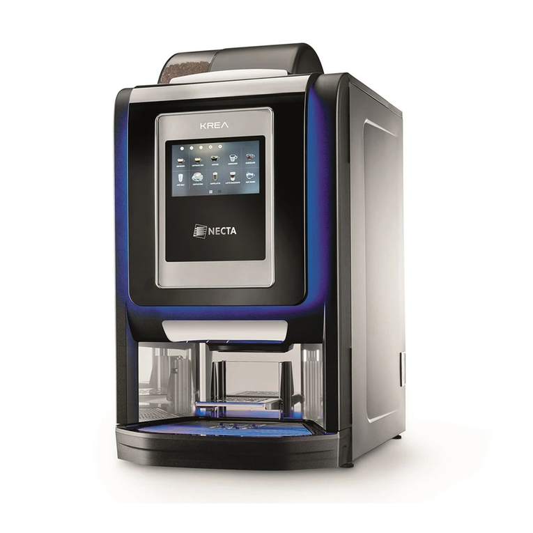
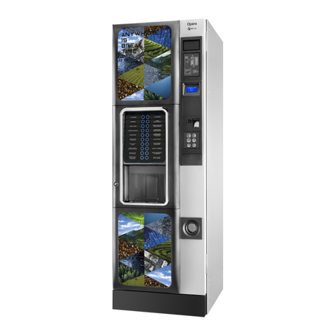
EVOCA Opera Touch Owner's manual

INSTALLATION, OPERATION, MAINTENANCE
Translation of original instructions
EN English
Doc. No. H6095EN00
Edition 1 02 - 2023
Opera Touch ESB7-R/US 120V


EVOCA S.p.A.
ad unico socio
Sede amministrativa, operativa e legale: Via Roma 24
24030 Valbrembo (BG) Italia
Tel +39 035 606111
Fax +39 035 606463
www.evocagroup.com
Cap. Soc. € 41.138.297,00 i.v.
Reg. Impr. BG, Cod. Fisc. e P.IVA: 05035600963
Reg. Produttori A.E.E.: IT08020000001054
Cod. identicativo: IT 05035600963
01/11/2022

integration of radio modules
In compliance with the national laws in
force, the manufacturer must check the
compliance of the radio equipment with
the essential requirements of the national
legislation.
The procedure used to check compliance
is at the manufacturer’s discretion.
If a radio module is built in a “non-radio”
equipment, the subject integrating the
module will become the manufacturer of
the end product and it must therefore check
the compliance of the end product with the
essential requirements of the national laws
in force in the country of installation of the
equipment.
As a matter of fact, the integration of radio
modules in other products can inuence
the compliance of the end product with the
essential requirements of the national laws
in force.
definitions according to the law
The manufacturer is a natural person who
or a public body which manufactures radio
equipment and/or electric material or has it
engineered, manufactured or marketed by
putting its own trademark or name on it.
An importer or distributor who places
radio equipment or electric material on the
market by putting its own name or trade-
mark becomes the manufacturer.
An importer or distributor who makes any
change to radio equipment or electric mate-
rial already placed on the market to such an
extent that the said change may condition
the compliance with the listed directives
is held to be the manufacturer and it must
therefore assume the relative obligations
according to the said directives.
Symbology
The following symbols may be present
inside the machines, according to models
(signs of danger)
Attention: dangerous voltage
Power o before removing the
cover
To reduce the risk of re or
electric shock, don’t remove
the cover. No user-servicea-
ble part inside.
Repairs should be done by
authorized service personel
only.
Attention
Danger of crushing your han-
ds
Attention
Hot surface
The signs of danger must be readable
and visible; they shall be neither hidden
nor removed. Damaged or unreadable
labels must be replaced.

Warnings
This document intended for the technical
personnel is made available in the electron-
ic format at the manufacturer’s (reserved
area web site).
for installation
The installation and any subsequent
maintenance operation shall be carried
out by the personnel skilled and trained
on the utilisation of the machine ac-
cording to the rules in force
The use of kits and/or accessories not
type-approved by the manufacturer can not
guarantee the observance of safety stand-
ards, in particular for live parts.
The installer will be the sole person respon-
sible for any damage improper installation
may cause to the machine or to things and
people.
The manufacturer declines all responsibility
for the use of non type-approved compo-
nents.
Assembly and any testing operation
must be carried out by qualied per-
sonnel who have a specic knowledge
of the machine operation from the point
of view of electric safety and health
rules.
The intactness of the machine and its
compliance with the standards of rel-
evant installations must be checked by
skilled personnel at least once a year.
Package materials must be disposed of in
observance of the environment.
For the vending machines of hot drinkts
only
The machine is equipped with an automatic
washing system for the mixers with the rela-
tive water circuit and the brewing unit.
If the machine is not used for some time
(weekends, etc.) even for pauses longer
than two days, it is recommended to enable
the automatic washing functions (e.g. be-
fore starting to use the VM.
for use
The machine can be used by children over
8 years and by people having reduced
physical, sensorial or mental skills under
the supervision of people responsible for
their safety or specically trained on the
use of the machine.
Children shall not be allowed to play with
the machine by the people in charge of
their supervision
Children shall not be allowed to clean or
service the machine.
for the environment
Some tricks will help you to protect the
environment:
-use biodegradable products to clean the
machine;
-properly dispose of all the packages of the
products used to fill and clean the ma-
chine;
-power off the machine during inactivity for
energy saving.
for dismantling and disposal
When dismantling the machine, it is rec-
ommended to destroy the machine rating
plate. The symbol shows that the ma-
chine can not be disposed of as
common waste, but it must be
disposed of as it is established by
the 2012/19/EU (Waste Electrical
and Electronic Equipment - WEEE)
European Directive and by the national
laws arising out of it in order to prevent any
negative consequence for environment and
human health.
The dierentiated collection of the machine
at the end of its life is organised and man-
aged by the manufacturer.
For the correct disposal of the machine
contact the sales point where you have
purchased the machine or our after-sales
service.
The unlawful disposal of the machine im-
plies the application of the administrative
sanctions provided for by the rules in force.
Attention!
If the machine is equipped with a cooling
system, the cooling unit contains HFC-
R134a uoridised greenhouse eect gas
ruled by the Kyoto protocol, the total heat-
ing potential of which is equal to 1300.
for the privacy
Only for the machines having a video ca-
mera and/or webcam.
The video camera and/or webcam for facto-
ry settings is disabled; if enabled, it shoots
soundless imagines without being able to
store them.
The Customer acknowledges that he/she
will become the Holder of the personal data
acquired if the video camera and/or web-
cam built in the equipment is activated.
Starting from that time, the Holder will assu-
me all the relative rights and duties accor-
ding to the provisions in force on the matter.


English
INTRODUCTION 1
transport and storagE 1
in casE of failurE 2
idEntification of thE machinE and its fEaturEs 2
positioning thE vEnding machinE 3
tEchnical fEaturEs 3
variablE combination lock 6
CLEANING AND LOADING 7
switchEs and safEty dEvicEs 7
hygiEnE and clEaning 8
using thE vEnding machinEs of hot drinks 8
coNtrols aND iNformatioN 9
proDuct loaDiNg 9
coffEE bEans 9
instant products and sugar 10
rEfErEncE cup spEcifications 10
cups 10
pErioDical opEratioNs 11
clEaning mixErs and food circuits 11
clEaning thE brEw unit 13
sugar rElEasE 13
dispEnsing compartmEnt 14
mixEr channEls 15
clEaning thE watEr supply tank 15
powEr on 15
sErvicE intErruption 15
wasH cyclEs 15
INSTALLATION 16
door switch 17
connEctivity switch 17
unpacking thE machinE 18
paymEnt systEm assEmbly 18
watEr supply 19
dEcalcifiEr 20
ElEctric connEction 21
nEtwork connEctions 22
mastEr / slavE bank connEction 23
first powEr-oN 24
sanitising for thE first timE 24
opEratioN 25
brEw unit 25
cup sEnsor 26
dispEnsing compartmEnt lighting 27
controlling and adjusting sEttings 27
grindEr-dosErs 27
instant dispEnsing 30
usE of usb kEys 31
connEctivity 31
touch scrEEn 32
Normal opEratioN moDE 32
drink dispEnsing 32
softwarE architEcturE 33
PROGRAMMING 34
accEss to programming mEnus 34
Entry of valuEs 35
Daily actioNs 36
washing and rinsing 36
filling canistErs 36
cash actions 36
slavE machinE rEmotE display 36
sEttiNgs of sElEctioNs 37
arrangEmEnt of sElEctions 37
catEgoriEs 37
products 37
contEnt of thE machinE 42
macHiNE sEttiNgs 43
configuration 43
modify intErfacE strings 44
display sEttings 44
gEnEral display sEttings 44
playlist 45
sEttings of input sEnsors 45
cup sEnsor 45
calibrations 46
output sEttings 47
maintEnancE 48
gEnEral sEttings 48
boilEr paramEtErs 49
prE-dispEnsing sEttings 49
mastEr slavE sEttings 49

macHiNE iNformatioN 50
failurEs 50
statistics 52
favouritEs 52
machinE idEntification numbEr 53
installation datE 53
tEchnical support contacts 53
ENErgy saviNg 53
sEttings 53
EnErgy saving timE bands 54
paymENt systEms 55
protocol 55
pricEs 58
import / Export 59
Export Evadts 59
vidEo 60
imagEs 60
backup 60
logfilE of failurEs 60
systEm 61
Export mEnu trEE 61
display log filEs 61
Export log filEs 61
systEm information 61
import / Export thE translations of strings 61
Export thE sEttings of rEcipEs 61
advancEd functionalitiEs 61
tEchnical fEaturEs 61
filling and Emptying thE boilEr 63
complEtE sElEctions 63
rEstorE sEttings by dEfault 63
schEdulEd EquipmEnt rEstart 63
datE and timE sEtup 63
languagE 63
usErs’ profilEs 64
nEtwork 64
softwarE updatE 65
information 65
coNNEctivity 66
Email sEttings 66
MAINTENANCE 67
gEnEral forEword 67
main switch 68
connEctivity switch 68
brEw unit maintEnancE 69
pErioDical opEratioN 70
sanitising 70
ElEctronic boards 73
cpu board 74
actuation board 75
boilEr control board 76
currEnt rEgulator board 76
powEr supply unit 76
fan rEplacEmEnt 77
boilEr hEat protEction 77
softwarE installation and/or updatE 78
APPENDIX 79

02-2023 6095 00 1
Introduction
The technical documentation supplied
is an integral part of the equipment and
it must therefore accompany the equip-
ment whenever it is either moved or
transferred to enable the various opera-
tors to consult it.
Before starting to install and use the ma-
chine, it is necessary to carefully read and
understand the content of the documenta-
tion since it can supply important informa-
tion on installation safety, utilisation rules
and maintenance operations.
The manual is divided into tree chap-
ters.
The is intended to describe
the ordinary lling and cleaning operations
that shall be carried out in areas of the ma-
chine that can be accessed with the simple
use of the door key, without using any other
tool.
The second chapter contains the instruc-
tions for correct installation as well as the
information necessary for optimal utilisation
of the machine performance.
The third chapter is intended to describe
the maintenance operations involving the
use of tools for access to potentially dan-
gerous areas.
The operations described in the second
and third chapter must be carried out
only by the personnel who have a spe-
-
tion from the point of view of electric
safety and health rules.
TRANSPORT AND STORAGE
traNsport
To avoid any damage to the equipment and
any injury to the people, the equipment
must be handled with great care.
While handling, there is the danger of
crushing one's hands and/or feet: never
shoes.
Handle the equipment by using lifting
means suitable for the size and the
weight of the equipment (e.g. lifting
Lifting means may only be used by per-
Please avoid:
-overturning and/or tilting the equipment;
-dragging or lifting the equipment by means
of ropes or alike;
-lifting the equipment by its sides;
-shaking or impacting the equipment and
its package.
storagE
The storage area must be dry and its tem-
perature lie between 32 and 104 °F
If the equipment should freeze, condition it
at a temperature between 32° and 104 °F.
Wait for the temperature of the equipment
to adjust to the room temperature before
powering it on.
Before powering on the equipment, please
wait for the humidity condensate (if any) to
dry completely.

202-2023 6095 00
IN CASE OF FAILURE
In most cases, any technical problem can
be solved by carrying out minor operations.
As a consequence, we suggest carefully
reading this manual before contacting the
manufacturer.
In case of failures or malfunctions that can
not be solved, please apply to:
Evoca S. p. A.
Via Roma 24
24030 Valbrembo
Italy - Tel. +39 035606111
IDENTIFICATION OF THE
MACHINE AND ITS FEATURES
Every single machine is identied by a spe-
cic serial number that can be found on the
rating plate arranged inside.
The plate is the only one recognised by the
manufacturer and it contains all the data
that enable the manufacturer to supply
technical information of any kind in a quick
and safe manner and to facilitate the man-
agement of spare parts.
TYPECODE MODEL SERIAL NR
BOILER SOLUBLE
PRESSURE Mpa
CAPACITY dm3
MAINS WATER PRESSURE
VOLTAGE FREQUENCY
POWER CURRENT
WPOWER
CAFE VAPOUR
1
2
3
4
5
6
7
8
9
10
Fig. 1
1. product code
2. type
3. model
4. operating voltage
5. absorbed power
6. boiler data
7. serial number
8. operating voltage frequency
9. current
10. water network features

02-2023 6095 00 3
POSITIONING THE VENDING
MACHINE
The machine is not suitable for installation
outdoors. It must be installed in a dry room
and far from any source of heat at a tem-
perature ranging from 41 °F to 93 °F. It can
not be installed in a room where water jets
are used for cleaning (e.g. large kitchens,
etc.).
The machine must be installed near a wall,
but in such a way that the back is min. 1,57
inch far from the wall in order to provide for
regular ventilation; in no case, it shall be
covered with any piece of cloth or alike.
The maximum inclination shall not exceed
2 degrees. If necessary, level it by using the
adjustable feet.
TECHNICAL FEATURES
23.62
47,24
29,13
49,21
72,04
Fig. 2
Weight 297 lb
Voltage 120 VAC
Frequency 60 Hz
Maximum power 1850 W
NoisE lEvEl
The continuous sound pressure level is
below 70 dB.

402-2023 6095 00
watEr supply
Supplied by the network, the water pres-
sure of which lies between 7,25 psi and
123,28 psi.
The machine software can manage the
water supply from an internal tank (optional
kit).
cups
Machine Capacity: 85 cups per turret / 340
total
The capacity has been measured with the
reference cup specified on page 10 and
may vary if different cup models are used.
For machine proper functionning, the cups
used must have the same specifica-tions
than the reference cups.
paymENt systEm
The machine can be electrically arranged
for the systems with an Executive, BDV and
MDB protocol and for the assembly of 24
Vdc validators.
The space is not only arranged to accom-
modate the coin mechanism, but also to
assemble the most widespread payment
systems (optionals).
salEs pricEs
A dierent price can be set for every single
selection.
The sales price is the same for all selec-
tions according to the standard setup.
coiN box
Made of sheet iron. Cover and lock avail-
able as accessories.
EsprEsso rEgulatioNs
-Coffee granulometry
-Coffee dose
-Water dose
iNstaNt rEgulatioNs
-Instant powder doses
-Water dose
tEmpEraturE rEgulatioN
The boiler temperature can be set up via
software.
approvals
-Cup presence
-Water presence
-Coffee presence
-Coffee unit position
-Liquid waste empty
-Operation temperature reached
safEty DEvicEs
-door switch
-connectivity disable micro switch with
open door
-manually resettable boiler safety thermo-
stat
-air-break float jam
-anti-flood solenoid valve
-float controlling liquid waste full
-boiler probe short-circuit / interruption
control
-protection with board and coin mechanism
supply transformer fuse
timE-basED protEctioN for:
-Pump
-Coffee unit ratio-motor
-Coffee dispensing
-Grinder
-Column shift motor
HEat protEctioN of:
-Ingredient motors
-Coffee unit ratio-motor
-Coffee release electromagnet
-Pump
-Whipper motors
-Grinder motor

02-2023 6095 00 5
caNistEr capacity
the machine may have dierent canister
combinations.
The indicative product quantity they can
contain is:
Coee beans (ES version) 7,05 Lb.
canister capacity
Coee
instant
1.8 Lt.
2.5 Lt.
4.5 Lt.
6 Lt.
0,9 Lb
1 Lb.
2 Lb.
3 Lb.
Chocolate
instant
2.5 Lt.
4.5 Lt.
6 Lt.
4 Lb.
7 Lb.
9,9 Lb.
Milk
instant
2.5 Lt.
4.5 Lt.
6 Lt.
1,5 Lb.
2,64 Lb.
3.74 Lb.
Tea
Instant lemon
2.5 Lt.
4.5 Lt.
6 Lt.
4,4 Lb.
7,7 Lb.
11 Lb.
Sugar 2.5 Lt.
4.5 Lt.
6 Lt.
4,4 Lb.
7,7 Lb.
11 Lb.
Ginseng 2.5 Lt.
4.5 Lt.
6 Lt.
3,96 Lb.
-
-
Broth
instant
2.5 Lt.
4.5 Lt.
6 Lt.
3,08 Lb
5,51 Lb.
7,71 Lb.
accEssoriEs aND kits
Accessories and kits can be mounted on
the machine to vary performances thereof.
The accessories and kits that can be ap-
plied on the equipment are made available
at the manufacturer’s.
The accessories and kits are supplied with
mounting and testing instructions that shall
be strictly followed to preserve the machine
safety.
The installer is the sole person responsi-
ble for any damage improper installation
may cause to the machine or to things and
people.
Important !!!
The use of accessories and kits not type-
approved by the manufacturer can not
guarantee the observance of safety stand-
ards, in particular for live parts.
The manufacturer declines all responsibility
for the use of non type-approved compo-
nents.
Assembly and any subsequent test-
ing operation must be carried out by
from the point of view of electric safety
and health rules.

602-2023 6095 00
VARIABLE COMBINATION LOCK
Some models are supplied with a variable
combination lock.
The lock is complete with a silver key, with
the standard combination, for opening and
closing.
It is possible to customise the locks by us-
ing a kit made available as an accessory
and intended to change the lock combina-
tion.
The kit is composed by a change key
(black) of the current combination as well
as by change (gold) and use (silver) keys of
the new combination.
Sets of change and use keys with other
combinations can be supplied upon re-
quest.
Moreover, further sets of use keys (silver)
may be requested by specifying the combi-
nation stamped on the keys.
usual opening operations since this
To change the combination:
1. Open the door of the equipment to avoid
having to force the rotation;
2. Slightly lubricate by using a spray inside
the lock;
3. Insert the current change key (black) and
turn it until you reach the change posi-
tion;
4. Remove the current change key and
insert the change key (gold) with the new
combination;
5. Turn the change key slightly several
times without completing the rotation
6. Turn it until you reach the close position
and remove the change key.
The lock has now assumed the new combi-
nation.
no longer used.
time, it is recommended to lubricate the
Other types of lubricants may trap dirt
Fig. 3

02-2023 6095 00 7
Chapter 1
Cleaning and Loading
The machine is not suitable for installation
outdoors. It must be installed in a dry room
at a temperature ranging from 41 °F to 93
°F. It can not be installed in a room where
water jets are used for cleaning (e.g. large
kitchens, etc.).
Before cleaning and loading, wash
your hands and wear disposable
gloves: the use of gloves is not remov-
ing the need for hand hygiene.
SWITCHES AND SAFETY DEVICES
Door switcH
Whenever you open the door, a special
switch will power o the electric installation
of the equipment to allow the user to carry
out the ordinary lling and cleaning opera-
tions described here below in totally safe
conditions.
All the operations requiring the ma-
chine to be directly connected to a
source of electricity when the door is
open must be ONLY carried out by the
coNNEctivity switcH
On opening the door, a special switch will
deactivate the connectivity components of
the equipment.
When the door is open, the drives of func-
tional units and/or remote control are disa-
bled.
All the operations requiring the
machine to be directly connected to
a source of electricity and the con-
nectivity functions to be active when
the door is open must be ONLY car-
1
2
3
4
5
6
7
89
Fig. 4
1. Waste bucket full
2. Dispensing compartment
3. Door switch
4. Mobile nozzles
5. Brew unit
6. Cup stacker
7. Canister
8. Mixer
9. Connectivity switch

802-2023 6095 00
USING THE VENDING MACHINES
OF HOT DRINKS
The dispensers of drinks in open canisters
may be only used for selling and dispens-
ing drinks obtained by:
-Brewing of products such as coffee and
tea;
-Reconstituting instant or freeze-dry
packed products;
These products shall be declared as “suit-
able for automatic dispensing” in open
canisters by the manufacturer.
Dispensed products shall be consumed
immediately. Under no circumstance
for later consumption.
Any other use shall be considered as im-
proper and thus potentially dangerous.
HYGIENE AND CLEANING
This manual shows the potential criti-
cal points and gives the instructions
necessary to control any bacterial pro-
liferation.
On the basis of the health and safety
rules in force, the operator of the vend-
ing machine shall apply the self-control
procedures established according to
the provisions of the HACCP (Hazard
-
tive and the national laws.
At the time of the installation, it is nec-
essary to completely sanitise the water
circuits and the parts in contact with
-
terium that may have built up during
storage.
It is recommended to use sanitising prod-
ucts to clean the surfaces, even if not di-
rectly in contact with foodstus.
Some parts of the machine can be dam-
aged by aggressive detergents.
The manufacturer disclaims all responsibil-
ity for any damage caused by the non-ob-
servance of the above or the use of aggres-
sive or toxic chemical agents.
before carrying out any maintenance
operation requiring the disassembly of
components.

02-2023 6095 00 9
CONTROLS AND INFORMATION
The controls and information for the user
are arranged outside.
All messages are displayed on the touch
screen of the machine.
6
7
8
9
10
11
5
1
2
3
4
Fig. 5
1. Lower aesthetic panel
2. Dispensing compartment
3. Lock
4. Touch screen
5. Upper aesthetic panel
6. Advertising space
7. Space for bill validator
8. Advertising space or cashless systems
9. Coin return button
10. Coin insert
11. Coin return
PRODUCT LOADING
that they have been preserved accord-
ing to the producer's instructions for
storage and holding temperature.
date.
The products shall be declared as “suitable
for automatic dispensing” in open canisters
by the manufacturer.
Products may even be loaded if canisters
are partially full.
COFFEE BEANS
It is advisable to use good quality cof-
fee beans to avoid any malfunction of the
equipment due to the presence of impuri-
ties.
1. open the canister cover.
2. fill with coffee beans.
3. make sure that the canister shutter is
open

10 02-2023 6095 00
INSTANT PRODUCTS AND SUGAR
It is advisable to use quality instant prod-
ucts to avoid any malfunction of the equip-
ment due to the presence of impurities.
1. open the instant powder canister cover.
2. fill with instant powder
3. close the cover carefully.
-
ing.
have loaded are not lumpy.
MAX
Fig. 6
REFERENCE CUP
SPECIFICATIONS
Fig. 7
CUPS
The cup dispenser shelf has got a double
articulated joint intended to improve the
accessibility to the cup dispenser for lling
columns.
To load the columns, act as follows:
-Open the machine door
-Pull the shelf to release the dispensing
compartment
-Turn the shelf to the outside
-Remove the cover from the cup stacker;
-Load the cups
1
2
Fig. 8
1. Cover
2. Cup column
Capacity 12 oz
Height 114.50 mm
Diameter 81.20 mm
Weight 8.50 g
Type Vending
Line Single Wall
Material PE Coated Paper

02-2023 6095 00 11
PERIODICAL OPERATIONS
This manual shows the potential criti-
cal points and gives the instructions
necessary to control any bacterial pro-
liferation.
On the basis of the health and safety
rules in force, the operator of the vend-
ing machine shall apply the self-control
procedures established according to
the standards of the HACCP (Hazard
-
tive.
Clean and sanitise the machine and the
parts in contact with the foodstus, as it
is described by the following paragraphs,
whenever you load products or more fre-
quently and according to the utilisation of
the machine, the inlet water quality and the
products in use.
It is necessary not only to remove any pow-
der residue from the parts outside brewers
and mixers, in particular in the funnel area,
but also to sanitise the parts in contact with
the mixer drink.
It is absolutely forbidden to direct water
CLEANING MIXERS AND FOOD
CIRCUITS
Whenever products are loaded and/or
weekly or more frequently, according to the
use of the machine, the inlet water quality
and the products in use, sanitise the mixers.
The parts to be cleaned are: powder de-
posit drawers, mixers and the conduit in-
tended to dispense instant drinks
It is absolutely forbidden to use water
3
5
2
1
6
4
Fig. 9
1. Powder funnel
2. Splash-guard ring
3. Water conveyor
4. Mixer impeller
5. Powder port
6. Rear cover

12 02-2023 6095 00
To clean the mixers, act as follows:
1. open the cover of mixers and lift the pow-
der ports as far as the retainer;
2. detach the instant drink tube from the
water funnel connection
3. rotate the ring nut intended to fasten the
water funnel counterclockwise and re-
move the mixer from the machine
4. separate all components (the funnels of
instant products, water funnels, convey-
ors, powder deposit drawers)
5. remove the mixer impeller;
Fig. 10
6. dip the components into a container with
the sanitising solution you have prepared
before for about 20 minutes, wash and
make sure that you have mechanically
removed visible residues and films by
using, if necessary, pipe cleaners or
brushes;
7. re-assemble the impellers
8. re-position the mixer.
Make sure that the water funnel is prop-
erly inserted.
9. rotate the ring nut intended to fasten the
water funnel clockwise to secure the
mixer to the machine
after having assembled the parts, act
as follows, any way:
-wash the mixers and add some drops of
the sanitising solution into the various fun-
nels.
-rinse the parts abundantly to remove any
residue of the solution in use.
All the operations requiring the ma-
chine to be directly connected to a
source of electricity must be ONLY car-
Table of contents
Other EVOCA Vending Machine manuals
Popular Vending Machine manuals by other brands
Jofemar
Jofemar vision multiseller Installation and maintenance guide

VeriFone
VeriFone UX301 installation guide
Cafection
Cafection EMBLEM Service & installation manual
Westomatic
Westomatic Sigma Touch Operator's & installation manual

Goldmedal
Goldmedal 5300 instruction manual
Elektral
Elektral Tru-VEND Maxi-Kafe Instructions for use & maintenance manual
COFFEtek
COFFEtek Neo + Operator's guide
Crane
Crane P Series manual
Sanden
Sanden Vendo Vue SXY 30 manual
Crane
Crane Dixie-Narco Glassfront BevMax 3 5800 Installation & setup guide
Necta
Necta Zenith Fresh Brew Instant Installation, operating and maintenance manual
CribMaster
CribMaster ProStock Removal and Replacement
