AutoCrib AUTOLOCKER FX User manual

1 | P a g e
1-800-671-6501 | autocribsupport.com
2882 Dow Avenue Tustin, CA 92780
Operation Manual
Last Revision December 2018

2 | P a g e
Instructions supplied with the machine are in English. Manufacturer will translate instructions as
necessary. English instructions are considered the original instructions.
Dispensing Machine Limited Warranty
AutoCrib incorporated warrants that its hardware products (see separate warranty agreement for
software products) are free of defects in material and workmanship in accordance with the terms
and conditions stated below. AutoCrib will repair or replace any machine, sub system or
component part that fails during the warranty period.
Standard Warranty Period
For a period of 12 months, following after the actual ship date from AutoCrib to the first
purchaser of use. The warranty period covers all components, sub systems, and complete
machines subject to the limitations and exclusions below.
Software and Technical Support
The standard AutoCrib warranty covers all software systems required for operation of your
AutoCrib equipment including software and firmware embedded, hosted through a client server
network, or hosted on via AutoCrib.Net web based hosting system for a period of 12 months,
following the actual ship date from AutoCrib. Included in the warranty is access to our 24-hour
technical support staff and entitles buyer to any and all software upgrades during that time.
Annual software support can be purchased at the current rate after the initial warranty period
expires. You are not required to purchase extended hardware maintenance to purchase extended
software support.
Extended Warranty Period
For a period of X months as defined in the extended warranty contract, following the actual ship
date from AutoCrib to the first purchaser of use. The warranty period covers all components,
sub systems, and complete machines subject to the limitations and exclusions below.
Any parts or services replaced or serviced pursuant to this warranty are warranted only for the
balance of the remaining warranty period. AutoCrib will dispatch an AutoCrib technician,
authorized AutoCrib dealer technician, or a certified third party technician to your facility to
perform any necessary troubleshooting tasks. It is your responsibility to provide an internet
connection with proper permissions to allow AutoCrib technical support associates to access the
controlling computer as well as the individual machines. If you do not provide this, you will be
charged an hourly rate at then current hourly rate for onsite troubleshooting services. Any
defective parts must be returned to AutoCrib within 30 days at your expense. You must indicate
the RMA number on the box(es) that will contain any and all defective parts to be returned. If
you do not provide the RMA number or fail to send the defective part back to AutoCrib you be
charged for the defective part.
Further, no authorized AutoCrib dealer/distributor is authorized to waive, modify, or change any
terms, conditions, or limitations of this warranty. This warranty is a part of the invoice which the
warranted machine or hardware relates.

3 | P a g e
Machines and Systems purchase through an authorized AutoCrib Distributor
All AutoCrib systems purchased through an authorized AutoCrib Distributor may contact their
distributor or AutoCrib directly. AutoCrib technical support will make every effort to correctly
troubleshoot the machine/system and determine the defective part and the correct course of
action to repair said machine or system.
AutoCrib provides depot level warranty coverage, which is defined as:
Depot level warranty means a new part/subsystem/machine will be shipped overnight to you or
your authorized distributor and billed to you or your distributor at the then current price. Your
distributor is required to ship the defective part/subsystem/machine back to AutoCrib within 30
days from the ship date of the replacement part. You agree to contact AutoCrib customer service
and get an “RMA” (return material authorization) number before you ship the defective part
back. Upon receiving the defective part, AutoCrib will issue an offsetting credit to your
company or authorized distributor per your instruction.
Limitations and Exclusions:
This warranty shall not cover or include any of the following and AutoCrib shall have no liability
with respect to:
Defects or damages which result from accident, misuse, abuse, lack of recommended or
reasonable maintenance, improper repairs or parts replacements, use of replacement parts not
conforming to AutoCrib standards, unauthorized modifications or general neglect including
electrical spikes, surges and sags caused by poor power management, thunderstorms or acts of
God or lack of normal power conditioning for electronic manufacturing equipment.
Damage caused by exposure to liquid spills, collision, fire, theft, freezing, vandalism, riot, war,
explosion or objects striking the machine such as fork trucks or exposure to abnormally corrosive
conditions or entry by insect or vermin or foreign objects or mispackaged or misplaced product
inside the machine.
Routine replacement made of consumable parts such as but not limited to light bulbs, plastic
breakable lock boxes, batteries, RFID tags, printer paper rolls, printer cartridges etc.
Routine maintenance services such as lubrications of drive trains or actuation solenoids. (See
appropriate AutoCrib manual for details)
Subsystems and attachments to the hardware/machine not manufactured by AutoCrib that are
subject to warranties of the manufacturers of such items.
Example: Uninterruptible power supplies, surge protectors etc.

4 | P a g e
Modifications and Upgrades:
AutoCrib reserves the right to make certain changes in designs or changes and improvements in
its products at any time without obligation to make such changes or improvements in its products
previously manufactured.
Limitation of Liability:
AutoCrib makes no warranty with respect to automated dispensing equipment sold by it, express
or implied except as expressly set forth herein. AutoCrib’ s liability whether in contract or tort,
or any legal theory, arising out of warranties, representation, instructions or warnings, (or any
lack or inadequacy thereof), deficiencies, failures or defects on any kind, or from any cause shall
be limited solely to repairing or replacing defective parts (during normal business hours)
pursuant and subject to the foregoing provisions. Regardless of whether the buyer’s limited
remedy has failed of its essential purpose, AutoCrib shall not be liable in any event for any
special, indirect, incidental or consequential damages, including but not limited to lost profits,
nor shall any claim or recovery of any kind exceed the purchase price of the machine or system
to which such claim or recovery is made.
The foregoing warranty is in lieu of all other warranties, express or implied, and AutoCrib
disclaims any warranties of merchantability and fitness for use or a particular purpose. This
warranty is effective with AutoCrib installations beginning January 1, 2009.
AutoCrib Corporate Headquarters:
Address: 2882 Dow Avenue Tustin, CA 92780
Phone: Tool Free 1-(800) 671-6501, Local/International 1-(714) 274-0400
Email: [email protected]
Website: http://www.autocrib.com | http://www.autocribsupport.com
AutoCrib Authorized Representative:
AutoCrib EMEA Contact:
Address: Am Güterbahnhof 7 a, 21035 Hamburg Germany
Phone: +49 40 716 655 900
Email: [email protected] | [email protected]
Website: www.autocrib-emea.com | www.support.autocrib-emea.com

5 | P a g e
Table of Contents
Machine General Description & Features.................................................................................. 7
Equipment Supplied ..................................................................................................................... 8
Cautions......................................................................................................................................... 9
Machine Setup............................................................................................................................. 11
Tools needed for installation..................................................................................................... 11
Machine preparation ................................................................................................................. 11
Installation................................................................................................................................. 12
Management Station Configuration.......................................................................................... 18
Computer Setup ........................................................................................................................ 18
Restore the Database .................................................................................................................. 21
FX Lockers Software Configuration......................................................................................... 28
Stocking the FX Lockers............................................................................................................ 32
Create a Purchase Order and Tag.............................................................................................. 32
Stock the FX Lockers................................................................................................................ 34
Software Operations................................................................................................................... 38
Issue .......................................................................................................................................... 38
Manual Stock............................................................................................................................ 42
Physical by bin.......................................................................................................................... 45
Return........................................................................................................................................ 48
Locate........................................................................................................................................ 50
Categorization........................................................................................................................... 52
Create Categories...................................................................................................................... 54
Create Families ......................................................................................................................... 55
Create Types ............................................................................................................................. 56
Associating a Family to a Category.......................................................................................... 57
Associating a Type to a Family ................................................................................................ 58
Associating an Item to a Type .................................................................................................. 59
Using Categorization at the FX Lockers................................................................................... 60
Grid View.................................................................................................................................. 60
Image View............................................................................................................................... 61
Issuing Items using Category, Family, and Type ..................................................................... 62
Commonly Performed Procedures............................................................................................ 65

6 | P a g e
Exiting the software to access the Microsoft Windows desktop .............................................. 66
Appendix...................................................................................................................................... 67
Care and Maintenance............................................................................................................... 67
Technical Specification............................................................................................................. 68
Parts list..................................................................................................................................... 70
Parts list continued.................................................................................................................... 71
LED Lights Status:.................................................................................................................... 72

7 | P a g e
Machine General Description & Features
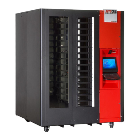
The AutoLocker® FX is the first and only locker system on the market designed to be
completely modular in every way. This platform lets you build a custom configured locker
system for the unique needs of your company. The rack mounted approach allows you to
configure exactly what you need and purchase only what you need. No need to purchase excess
lockers and use up valuable floor space. You decide the frame size, controller box, locker size,
power (Optional), and network switch (Optional). Locker modules are available in 12 different
sizes for you to choose from. Locker modules come in 3” (8cm) high increments with a standard
24” (61cm) depth and a wide variety of widths available that can be mixed and matched to
provide a customized solution. See-through windows with bright LED lighting allow the user to
quickly identify the items they want and then issue it through an intuitive touchscreen user
interface. Multistate LED status lights quickly identify which items are out on the floor as well
as the status of the items that are inside the lockers. The AutoLocker® FX also provides for
optional 110VAC power outlets so that battery operated tools and equipment can be charged
while in the locker. Further, the system will manage the charge time and always dispense the
item with the longest charge. E-Tools (laptops and iPads) can also be charged while managing
virus definitions and operating system updates.
Features:
•Stand-Alone or Add-On a RoboCrib®
•High-resolution 19” (48cm) touch display
•Small locker footprint
•Large see-through windows provide maximum visibility
•LED lighting clearly illuminates the product inside
•Informative status lights on each locker door or drawer
•Motor driven latches reduce jamming and maintenance issues
•Lockers can be numbered per the customer’s requirement
•Easily reconfigured by changing door sizes and dividers
•Special locker drawers available for laptops, tablets and eTools
•Ability to issue only items that are fully charged or with the most remaining battery life
first
•Can be configured with or without standard lockers
•Optional: 110v Power for keeping batteries and items fully charged
•Optional: Individual cooling fans and filtration systems to keep e-tools clean and cool
•Optional: Managed switch systems to push updates and virus definitions to laptops,
equipment, and e-tools
•Optional: Caster wheels make it easy to relocate lockers where you want them
•Power: 100-240VAC–50/60HZ, 2A/1.0A MAX

8 | P a g e
Equipment Supplied
▪Frame 24” Deep and 36” or 72” High (Optional Caster Wheels)
▪Modules (various configurations of doors & drawers which may include AC Power,
network, or fan upgrades)
▪Touch Controller (stand-alone unit) includes;
•Dell Optiplex 7040 Micro PC
•Touch Monitor 19” US Micro
•Keyboard with a mini trackpad
•Bar code reader
•CBI board
•12VDC power supply
•Cooling fan
•UPS Battery Backup (Installed in units shipped within North America, Canada, and
Mexico)
•2 Ethernet adapters (one to the CBI, one spare part)
•25 feet Cat 5 cables
▪Door Keys (4)
▪Operating Instructions (this manual)

9 | P a g e
Cautions
The following cautionary information should be reviewed before the machine is installed.
Following these requirements and warnings are required.
CAUTION: This machine is designed for indoor usage only. Any other
usage will void the Manufacturer’s Warranty.
Voltage and Polarity Check
It is important that this machine be hooked up to the proper voltage and
polarity for your country. Use a voltmeter to verify voltage and polarity
before connecting the machine to a wall outlet. For machines located in
North America, use the diagram below to verify correct voltages.
CAUTION: Any procedure marked with the symbol at left requires that
the Machine have the power applied and a shock hazard exists.
CAUTION: Different countries may have unique plug arrangements.
Ensure that the machine is properly grounded before operating.
CAUTION: The machine is a heavy item. Ensure that sufficient
personnel are available for lifting and transporting the machine. Use
proper lifting procedures and equipment.
CAUTION: The system components in this machine utilize static
sensitive components. Precautions for handling sensitive devices should
be observed when handling these items.
Voltage and Polarity Check (for Machines located in North America Only)
It is important that this machine is hooked up to proper voltage and polarity. Using a voltmeter or
a polarity tester, perform the following checks from the illustration below.

10 | P a g e
Electrical Color Codes:

11 | P a g e
Machine Setup
Tools needed for installation
▪Outlet Tester (May be purchases at electronics store)
▪Forklift with adjustable forks
▪Utility dolly
▪Phillips #2 Screwdriver
Machine preparation
The FX Locker unit is assembled and packed so that a minimum amount of time is necessary for
preparation to install it on location. The following steps are recommended to ensure correct
unpacking.
1. Shipping Damage
Thoroughly inspect the exterior of the box and/or wrapping for damage, which may have
occurred during shipment.
a. Verify “TipNTell” is intact. (See Diagram 1.1)
b. Note any damage or irregularities on shipping document.
c. Report any damage to delivering carrier and follow their instructions.
DO NOT SIGN FOR SHIPMENT IF ANY DAMAGE HAS OCCURRED, REFUSE THE
SHIPMENT!
2. Uncrate the FX Lockers
a. The FX Locker is a self-contained automated vending unit, ready to use right out
of the box with very little set-up. The machine is shipped in specially designed
packaging, and it should stay that way until it is positioned near its final location.
b. Using a cordless drill with a #2 Phillips head bit, remove screws on crate.
Carefully remove plywood and cardboard panels (Retain the screws and crate, in
case there is concealed damage and you need to return the machine.)
c. Use a Forklift to place the FX Lockers and pallet near the final location.
3. Remove the FX Lockers from Pallet
d. Remove ratchet shipping straps from the FX Lockers and from under the shipping
pallet.
d. Remove the inner shrink-wrap and bubble packaging from the machine.
e. Using a utility dolly move the FX Lockers to the final location. Insert the utility
dolly from the back of the FX Lockers frame to move.
Diagram 1.1

12 | P a g e
Installation
Physical Connections:
1. Move the machine to the desired location
2. Plug the FX AutoLocker into a grounded 110v receptacle
3. Unlock and pull Open the Touch Controller drawer using the key provided with the
machine shipment
4. Press and hold the UPS Battery power button for two seconds then release to turn on the
power (battery is located towards the back-left corner of the frame behind the touch
controller drawer).
Note: UPS is only provided with machines shipped within North America, Canada, and Mexico.
For machines shipped to countries outside those areas you will need to purchase and install a
compatible plug

13 | P a g e
5. Remove the provided blue 25 foot CAT5 able from the package
6. Using the key provided unlock the left front corner panel and pull straight out then set
aside
7. Feed the CAT5 cable through the opening in the chassis (from left to right) located on the
top left side of the drawer

14 | P a g e
8. Connect the right end of the CAT5 cable to the Ethernet Port located behind the PC
9. Run the left end of the CAT5 cable up the side of the chassis and feed through the
opening on the top left corner of the machine

15 | P a g e
10. Pull the cable through and connect to the network
11. Place the left front panel back on:
a. make sure the two studs fit into the round holes and turn the key to lock the panel
back in place
b. Align the three metal tabs that are located on the frame (bottom, middle, and top)
with the three slits located on the front panel cover
c. turn the key to lock the panel back in place
12. Close the Touch controller drawer and lock with the key provided, then pull open the
keyboard shelf

16 | P a g e
Additional Frames Connection
1. Using a utilities dolly, position the frames per the site plan
2. Ensure power is OFF at the UPS
3. Pull the ends of the DC Power & Data cables out of both adjoining frames
4. Connect the male power and hirose cables to the female power and hirose connectors
5. Turn on power at UPS - Internal LED strips should light up, and LEDs on the distribution
and latch boards should light up (Blue LED Blinking on the board = board is powered &
communicating with CBI controller)
6. Place the red backbone cover over the wiring connections, spanning the two frame
corners (Align the slots on the cover to the studs on the frame and tighten nuts)
DC Power –2 position Molex
Data –5 position Hirose

17 | P a g e
7. Make sure the red termination jumper is located on the last distribution board of the last
locker frame in the chain

18 | P a g e
Management Station Configuration
Computer Setup
1. Connect the monitor using the blue VGA cable
2. Connect the USB keyboard
3. Connect one end of the network cable (CAT5) to the PC, then connect the other end of
the network cable to the hub provided or LAN drop

19 | P a g e
4. Connect the power cables on the monitor and computer. If using a hub, connect the
power cable as well
5. Press the power button on the computer and monitor
6. Exit out of the AutoCrib software
7. Ask the network administrator to properly configure the network LAN settings on the
management station and FX Lockers.

20 | P a g e
1
Optical Drive
2
Optical Drive Eject Button
3
Optical Drive bay
4
Media Card Reader (optional)
5
USB 2.0 Connectors (2)
6
Drive activity light
7
Power button, power light
8
Diagnostic lights (4)
9
Headphone Connector
10
Microphone Connector
11
Network Connectivity Light
12
Power Connector
13
Back Panel Connectors
14
Expansion Card Slots (4)
15
Cooling Vents
16
Padlock Ring
17
Cover Release Latch
Dell Tower Ports
Table of contents
Other AutoCrib Vending Machine manuals