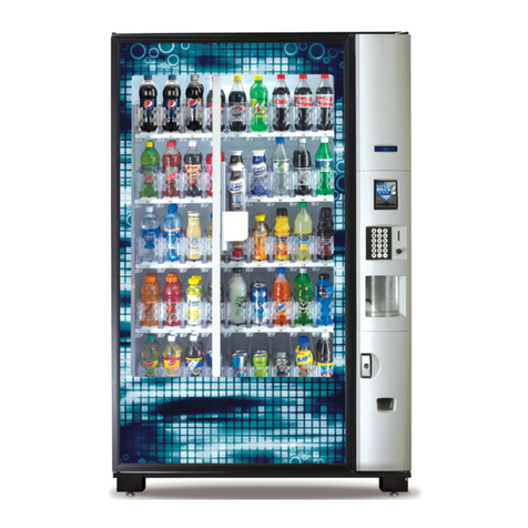
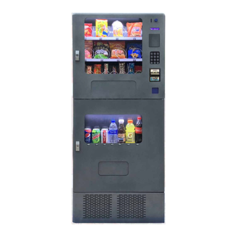
SandenVendo SVE C36-XS Operating instructions

© Date: 30/07/2020 - Revision: 1 - Code: 415430
User and maintenance manual
Narrow Stack
Extra Small SVE C36-XS
Small SVE C47-S
Medium SVE C48-M
Large SVE C4X-L
SandenVendo Europe S.p.A.
Regione Cavallino,2
15030 Coniolo (AL) - Italy
Tel. +39 0142.335111
Fax +39 0142.562348
E-mail: [email protected]
website: www.sandenvendo.com

SandenVendo GmbH
Italian Branch
Via Galeotto del Carretto 10
15033 Casale Monferrato (AL) –Italy
Tel.:+ 39 0142 234 220
Fax.:+ 39 0142 231 153
e-mail: [email protected]
SandenVendo GmbH (SVG)
Kolberger Str.7
40599 Düsseldorf
Germany
Tel.: + 49 211 740390
Fax: + 49 211 7488541
e-mail: [email protected]
www.sandenvendo.com
SandenVendo Spain
Sucursal en España
Poligono Industrial la Almeda
C/. Sant Ferrán, no. 92
E-08940 Cornella (Barcelona) - Spain
Tel. : +34 (0)93 4741555
Fax : +34 (0)93 4741842
e-mail: [email protected]
SandenVendo Belgium
Branch of SandenVendo GmbH
Avenue A. Van Oss 1 - Boîte 21
1120 Bruxelles - Belgium
Tel.: +32 (0)2 2682595
Fax :+32 (0)2 2682862
e-mail: [email protected]
SandenVendo France
Branch of SandenVendo GmbH
140 bis rue de RENNES
75006 Paris - FRANCE
Stéphane Bourdin Tel. : +33 6 59 25 87 81
Brice Passot Tel. : +33 6 38 63 67 54
SAV Jean Paul Riche Tel. : +33 6 40 30 83 17
e-mail: [email protected]

Index
Page 1 of 54
TRANSLATION OF THE ORIGINAL INSTRUCTIONS
© SandenVendo Europe SpA
1 GENERAL ADVERTISEMENT.............................................................................................3
1.1 Purpose of this manual...............................................................................................................3
1.2 To whom this manual is addressed.............................................................................................4
1.4 Manufacturer..............................................................................................................................6
1.5 Service centers...........................................................................................................................6
1.6 Warranty.....................................................................................................................................7
1.6 General safety warnings.............................................................................................................9
1.7 Security symbols and Pictograms.............................................................................................12
2 VENDING MACHINE IDENTIFICATION.............................................................................14
2.1 Identification Plate....................................................................................................................14
2.2 General Description..................................................................................................................15
2.2.1 Models Name.....................................................................................................................15
2.3 Technical features....................................................................................................................16
2.4 Description of components .......................................................................................................17
3 TRANSPORT, STORAGE AND INSTALLATION ..............................................................18
3.1 Transport and Storage..............................................................................................................18
3.2 Unpacking ................................................................................................................................19
3.2.1 Removing the wooden bases .............................................................................................20
3.2.2 Supplied Accessories.........................................................................................................20
3.3 Installation................................................................................................................................21
3.3.1 Installation environment features........................................................................................21
3.3.2 Placement..........................................................................................................................22
3.3.2.1 Installation spaces and spaces of use..........................................................................................23
3.3.3 Connection to power mains................................................................................................24
3.3.4 Stability..................................................................................................................................25
3.3.5 Installing the coin mechanism.............................................................................................26
3.3.5.1 Coinmech Connection MDB / Executive.......................................................................................27
3.3.6 Selection Laber Installation.................................................................................................28
3.3.6.1 Matching Selections to Columns ..................................................................................................28
4 USE AND OPERATION OF THE VENDING MACHINE.....................................................29
4.1 Proper Use...............................................................................................................................29
4.1.1 Distribution capacity ...........................................................................................................29
4.2 Access to internal parts ............................................................................................................30
4.2.1 Safety devices....................................................................................................................31
4.2.2 Board .................................................................................................................................32
4.2.2.1 SVE01 Board................................................................................................................................32
4.2.3 Operation NarrowStack Mechanism (N.S.).........................................................................33
4.2.3.1 Regulating the baffle (rear spacer) ...............................................................................................34
4.2.3.2 Regulating the delivery shelves....................................................................................................35
4.2.3.3 Setting of column setup 1D/2D/3D/4D..........................................................................................35
4.2.4 Products Charging..............................................................................................................36
4.2.5 Refrigerant System Operation............................................................................................37
4.2.5.1 Control Unit CAREL ir33 Description and Operation....................................................................38
4.2.5.1.1 Display...................................................................................................................................38
4.2.5.1.2 Keyboard...............................................................................................................................40
4.2.5.1.3 Displaying and setting the set point ......................................................................................41
4.2.5.1.4 Errors List..............................................................................................................................41
5 MAINTENANCE..................................................................................................................42
5.1 Warnings..................................................................................................................................42
5.2 Recommended cleaning products.............................................................................................43
5.3 Cleaning safety devices............................................................................................................43
5.4 Preventive maintenance...........................................................................................................43
5.5 Cleaning operations..................................................................................................................44
5.5.1 Daily Cleaning....................................................................................................................44
5.5.2 Weekly Cleaning ................................................................................................................44
5.5.3 Monthly Cleaning................................................................................................................44
5.5.4 Yearly Cleaning..................................................................................................................45
5.6 Assembly / Disassembly for Maintenance.................................................................................45
Index
Page 2 of 54
TRANSLATION OF THE ORIGINAL INSTRUCTIONS
© SandenVendo Europe SpA
5.6.1 LED Replacing ...................................................................................................................45

5.6.2 Door Gasket Replacement .................................................................................................45
5.6.3 Replacement Cam / Micro Motor Mechanism.....................................................................46
6 TROUBLESHOOTING........................................................................................................47
6.1 Door Errors...............................................................................................................................47
6.2 Mechanism Errors ....................................................................................................................48
6.3 Payment Device Errors.............................................................................................................49
6.4 Refrigerant System Errors ........................................................................................................50
7 OUT OF ORDER OPERATION...........................................................................................54
7.1 Disposal....................................................................................................................................54
7.2 Person in charge of disposal.....................................................................................................54
7.3 Sanctions..................................................................................................................................54

Instructions for the installer, maintenance
technician and final user
Page 3 of 54
© SandenVendo Europe SpA
1 GENERAL ADVERTISEMENT
1.1 Purpose of this manual
Before proceeding to install and use the
vending machine, it is necessary to read the
contents of this manual.
This manual is an integral part of the machine
and must therefore be kept intact and available to
hand for the machine’s entire productive life.
Any other document sent by SandenVendo is to be
attached to the manual to form a complete dossier
of the automatic vending machine.
Caution: failure to follow the instructions
contained in this manual may involve damages to
the machine and/or personnel.
Should this manual be lost or damaged, you
may request a copy from the manufacturer: please
enclose the serial number of your vending machine
with your request.

Instructions for the installer, maintenance
technician and final user
Page 4 of 54
© SandenVendo Europe SpA
1.2 To whom this manual is addressed
The manual contains the correct procedures for
the loading, use, routine / special maintenance
and installation of the Vending Machine.
This manual is addressed to those persons in
charge of loading, cleaning and routine
maintenance of the machine (Filler), to the final
user of the vending machine (User) and to those
persons in charge of installation, adjustment,
special maintenance of the vending machine
(Maintenance Engineer / Skilled technician).
User
This appliance can be used by children aged
from 8 years and above and persons with
reduced physical, sensory or mental capabilities
or lack of experience and knowledge if they
have been given supervision or instruction
concerning use of the appliance in a safe way
and understand the hazards involved.
Children shall not play with the appliance.
Cleaning and user maintenance shall not be
made by children without supervision.

Instructions for the installer, maintenance
technician and final user
Page 5 of 54
© SandenVendo Europe SpA
Operator
The intervention of the operator on the vending
machines is only intended for the loading and
routine cleaning operations to be carried out in
accessible areas with the sole use of the door
opening key, and without the use of other tools.
Maintenance Engineer / Skilled technician
The intervention of the maintenance engineer is
required for all operations that require the use of
tools for access to potentially hazardous areas,
the installation of the vending machine, the start-
up and the programming of the functions.
The maintenance technician must be
previously trained and instructed on the
interventions to be carried out on the vending
machine and limit them to what is within his
competence.
It is the responsibility of the purchaser to make
sure that the maintenance personnel are trained
and aware of all the information and instructions
indicated in the manual.

Instructions for the installer, maintenance
technician and final user
Page 6 of 54
© SandenVendo Europe SpA
1.4 Manufacturer
SandenVendo Europe in Europe has been making
significant advancements in the vending industry
for many decades and is a powerful partner for
excellence in quality, reliability and service.
SandenVendo Europe are a “one-stop shop
supplier”, offering a wide variety of vending
equipment for hot and cold beverages, snacks and
ice cream, but also related products such as
sophisticated payment systems and premium
coolers.
1.5 Service centers
Any technical problems that may occur can be
resolved by consulting this manual; in the event of
anomalies or malfunctions that cannot be resolved,
contact the Service Centres at the numbers shown
on the inside cover.
In case of a call it is good to know how to
indicate the data reported on the vending machine
serial plate.

Instructions for the installer, maintenance
technician and final user
Page 7 of 54
© SandenVendo Europe SpA
1.6 Warranty
The Warranty on the Vending Machine
components, starting from the date shown on the
delivery note, is for 12 months.
The warranty includes exclusively the parts
replaced, with lab our excluded.
Shipping cost of machines, defective parts and
spare parts are always at the customer's expense.
The Warranty does not include, damages to the
vending machine caused by:
Transport and/or handling
Operator errors
Lack of maintenance as explained in this manual
Failures and/or breakages not due to
malfunction of the vending machine
Damage which may be caused, directly or
indirectly, by persons, things or animals
Damage deriving from labour linked with the
installation, connection to the main supplies.
Improper use of the machine.

Instructions for the installer, maintenance
technician and final user
Page 8 of 54
© SandenVendo Europe SpA
The manufacturer’s responsibility is confined to the
correct use of the machine, in the limits indicated
in this manual.
"SandenVendo Europe S.p.A" declines all
responsibility for any damages caused to persons
and/or things as the result of:
- Incorrect installation
- Use of unoriginal spare parts
- Execution of changes unforeseen/unauthorized
by the manufacturer
- Improper use of the machine
- Connection to inadequate supply systems and
not in conformity with the regulations in force

Instructions for the installer, maintenance
technician and final user
Page 9 of 54
© SandenVendo Europe SpA
1.6 General safety warnings
Carefully read the manual before starting or
loading the vending machine
The vending machine is constructed in a
workmanlike manner. Its service life, electrical
and mechanical reliability will be more efficient if
it will be used correctly and regular maintenance
will be carried out.
This machine is not suitable for outside
installation.
This machine is not suitable for installation in
areas where water jets are used.
Protect the vending machine against weather
conditions.
Never position the vending machine in direct
sunlight.
To prevent hazards due to machine instability,
secure the machine according to the instructions.
Install the appliance so that the electrical plug
can be easily accessed afterwards.
The use of adapters, multiple sockets and/or
extensions is forbidden.
Use a differentiated protection system.
If the power cable is damaged, it must be
replaced by the manufacturer or by one of its
technical support personnel or by a qualified
electrician.

Instructions for the installer, maintenance
technician and final user
Page 10 of 54
© SandenVendo Europe SpA
Only maintenance technicians should remove the
protective covers.
Always read the programming manual before
operating the electronic board settings
Use only spare parts authorized by the
manufacturer
WARNING: Keep clear of obstruction all
ventilation openings in the appliance enclosure
or in the structure for building-in.
WARNING: Do not damage the refrigerant
circuit.
WARNING: In order to reduce flammability
hazards the installation of this appliance must
only be carried out by a suitably qualified person.
Original instruction in Italy.

Instructions for the installer, maintenance
technician and final user
Page 11 of 54
© SandenVendo Europe SpA
The pictures and illustrations in this document are
only indicative. SandenVendo Europe S.p.A. recalls
that the technical and performance of products can
change without notice.
“SandenVendo Europe S.p.A.”. reserves the right of
making changes on their vending machines without
any advice; moreover they declare that the vendors
listed in this manual are in conformity with the
following directives: 2006/42/CE (EC markings) and
2004/1935/CE.
“SandenVendo Europe S.p.A." assumes no liability
for the correctness of the contents or damages
caused by using this manual.
“SandenVendo Europe S.p.A." reserves the right to
make changes to this manual without prior notice.

Instructions for the installer, maintenance
technician and final user
Page 12 of 54
© SandenVendo Europe SpA
1.7 Security symbols and Pictograms
In the manual and/or on the machine, hazardous areas are shown with signs, plates, symbols
and icons that indicate danger or an obligation in each case.
Description
Pictogram / Secure Symbol
Indicates information regarding personnel safety
and machine integrity.
Compulsory for all personnel involved
Compulsory for all personnel involved to wear
protective gloves during maintenance of the
vending machine
Compulsory for all personnel involved to protective
clothing during maintenance.
Additional information is given.
i
Before carrying out this operation, refer to the
Instruction Manual.
In case of special operations and/or anomalies, a
particular mechanical adjustment and/or electrical
setting may be required.
Indicates a warning, failure to comply may involve
damage to the vending machine.
Danger
Indication of mains voltage.
Danger
Indication of the presence of cutting hazard.
Symbol ISO 7010W021
Warning
Risk of fire / flammable materials
Warning
Danger
Compulsory
Indicates the danger of electric shocks and
mechanical risks.
Caution
The vending machine must be fitted with a
grounding system.

Instructions for the installer, maintenance
technician and final user
Page 13 of 54
© SandenVendo Europe SpA
System contains refrigerant under high pressure.
Do not tamper with the system. It must be serviced
by qualified persons only.
Caution
Hazardous Area pay extreme care whilst operating
the vend mechanisms
Fuse symbol.
Fuse type and state indicator.
&
"Power Switch" button presence indicator
Ground connection indicator.
ON.
OFF.
Identification Plate
Vending machine identification and main technical
data
Equipment only suitable for internal use indicator.
Recycling this product goes toward reducing the
need of new materials and the accumulation of
waste.
Recycling
Lo smaltitore al ricevimento di un'apparecchiatura
con indicato il simbolo del cassone barrato ha
l’obbligo, prima di smaltirla, di selezionare i rifiuti
RAEE e di renderli eventualmente disponibili ad un
eventuale recupero.
Final inspection certificate.

Instructions for the installer, maintenance
technician and final user
Page 14 of 54
© SandenVendo Europe SpA
2 VENDING MACHINE IDENTIFICATION
2.1 Identification Plate
Each SandenVendo vending machine is identified by a model name and a specific serial
number, which can be found on the plate, located on the outside on the back of the vending
machine and inside above the drawer.
The plate is the only one recognized by the manufacturer as the vending machine
identification and contains all the data that allow the manufacturer to provide any type of
technical information and to facilitate the management of spare parts.
The following data are shown on the plate:
i
An identical plate is placed above the cooling system only with the data concerning the
system itself.
Attention!
It is absolutely forbidden to tamper or modify the data plate.
Important!
For any request to the service centers, always refer to this plate, indicating the specific data
printed on it.
Name of the manufacturer
Address and Logo
Conformity marking
Model
Serial Number
Supply voltage
Power frequency
Electrical power
absorbed
Max power of the
lamp used
Climate class
GWP value
expressed in
equivalent tons of
CO2
Global warming
potential
Relative humidity
Maximum current
draw
Fuses
Type and
quantity of
refrigerant gas

Instructions for the installer, maintenance
technician and final user
Page 15 of 54
© SandenVendo Europe SpA
2.2 General Description
The vending machine is to be used exclusively for the sale and distribution of drinks in bottle
or can.
The distribution takes place through a distribution cycle that allows you to take only one
product for each cycle. The distribution takes place until exhaustion of the products contained
in the vending machine. An alarm allow to notify the user of the status of availability for
distribution.
The vending machine is not a refrigerator, but allows you to moderately refrigerate the
products that are loaded.
Any other use is to be considered improper use and therefore at risk.
Do not introduce potentially dangerous products into the vending machine due to inadequate
temperatures. In this regard, follow the instructions on the products for the conservation rules
and the expiration dates of the same.
2.2.1 Models Name
SVE C36-XS
C = Can
Letter to indicate that the model is a
new generation Cans and Bottles
3 = Mechanism 3D
4 = Mechanism 4D
XS = Extra Small
S = Small
M = Medium
L = Large
Digit indicating the quantity of Narrowstack
columns that the model has.
6, 7, 8 e 10 (X = 10)
SVE = Sanden Vendo Europe

Instructions for the installer, maintenance
technician and final user
Page 16 of 54
© SandenVendo Europe SpA
Fig. 2.1
C
A
B
2.3 Technical features
Bottle and Can
C36-XS
C47-S
C48-M
C4X-L
Dimensions
Height (A)
1830 mm
1830 mm
1830 mm
1830 mm
Width (B)
650 mm
750 mm
850 mm
1015 mm
Depth (C)
800 mm
955 mm
955 mm
955 mm
Weight
280 Kg
300 Kg
340 Kg
375 Kg
Power supply
Nominal voltage
220 / 240 V
Nominal frequency
50 / 60 Hz
Max. power consumption
650 W
700 W
700 W
700 W
Fuses
F1-T10A ■ F2-T1A
Refrigeration unit
Compressor
8.77 cm³
8.77 cm³
8.77 cm³
8.77 cm³
Expansion
Direct with capillary tube
Cooling system
Forced air with evaporator 2 fans
Refrigerant type
* R290
GWP
3
3
3
3
Refrigerant charge
0.066kg
0.078kg
0.078kg
0.078kg
T e CO2
0,000198
0,000234
0,000234
0,000234
Adjustable temperature range
+1°C up to +25°C
Climate class
ST (+18°C up tp + 38°C)
Noise level
< 70 dB
Electronic control
MDB
Payment system protocol
MDB / Executive
*Equipment contains flammable gases.
The flammable gases are contained in hermetically sealed equipment conform at
IEC 60335-2-89 norms
WARNING: Keep clear of obstruction all ventilation openings in
the appliance enclosure or in the structure for building-in.
WARNING: Do not damage the refrigerant circuit.
WARNING: In order to reduce flammability hazards the
installation of this appliance must only be carried out by a suitably
qualified person.
WARNING: Don’t use electrical and mechanical device, unless
they are of the type recommended by the manufacturer.

Instructions for the installer, maintenance
technician and final user
Page 17 of 54
© SandenVendo Europe SpA
2.4 Description of components
1. Hole plugs for payment devices
2. Display
3. Coin Insert
4. Coin Return Button
5. Selections Buttons
6. Door Lock
7. Coin Return
8. Lower Grid
9. Delivery Area
10.Illuminated Panel (Decal)
11.Narrowstack Mechanism
12.Cabinet
13.Lower Internal Door
14.Support for Products
15.Product Exit Area
16.Refrigerant System Cover
17.Coin Box
18.Coinmech
19.Control Panel
20.Coin Return Motor
21.Board
22.Upper Interior Door
23.Door
1
3
4
5
6
7
8
9
10
2
9
11
13
23
12
14
15
16
17
7
18
19
20
22
21

Instructions for the installer, maintenance
technician and final user
Page 18 of 54
© SandenVendo Europe SpA
3 TRANSPORT, STORAGE AND INSTALLATION
3.1 Transport and Storage
Unloading from the vehicles of transport and handling of the vending machine must be carried
out only by competent personnel and with the use of suitable equipment’s for the load to be
handled.
The vending machine is positioned above two wooden bases, protected by a bag, by four
corners and by a retractable film.
Use a forklift, power-driven or manual, to unload the vending machine from the vehicles of
transport, the wooden bases allow the sockets on the 4 sides of the vending machine.
Attention!
It is forbidden to transport and / or place the vending machine in a horizontal position;
It is forbidden to drag or lift the vending machine with ropes, slings or other;
Avoid maneuvers that can cause sudden jolts and impacts to the vending machine.
In the event the machine is mistakenly laid horizontally, place in the upright position
and wait at least 12 hours before switching on; otherwise, damage may be caused to the
cooling system.
If the vending machine is not used immediately or is stored for long periods, check that
it is correctly packaged and positioned vertically.
Storage must be carried out in closed but well ventilated
places that do not have particular harmful characteristics to
the machine components, especially the electronic ones. It is
necessary that the environment is dry and with temperatures
not lower than 1°C.
Protect the unpainted parts from corrosion with suitable
greases or sprays; if necessary, stow it with dehydrating salts.
i
As long as the vending machine has the original
packaging, including wooden bases, it is possible
to overlap two.
Attention!
Unpacked vending machines are not stackable.
MODEL
A (mm)
B (mm)
C (mm)
GROSS WEIGHT (Kg)
C36
1960
665
810
300
C47
1960
765
965
320
C48
1960
865
965
360
C4X
1960
1030
965
395
C
A
B
This manual suits for next models
3
Table of contents
Other SandenVendo Vending Machine manuals
Popular Vending Machine manuals by other brands

American Games
American Games MAXIM 4200 Operator's manual

Atlantis
Atlantis Cafe Mini Series User manual and warranty card

Intelligent Vending
Intelligent Vending MULTI-6 installation instructions

Macas
Macas MACES7C-300-90-00 Series Service manual

VendNet
VendNet CB500-SA Service manual

Bag of Ice
Bag of Ice XL1900 product manual