The EDT is used by dealership technicians to interface with specific machines that have a Cont
(CAN) BUS as part of the electronic system architecture.
protocol adapter, carry case, and other items.
software application, cables, and 2x4 CAN USB Protocol Adapter.
The annual software subscription fe
dealership sells that are supported by the dealership. Software subscription is notcharged by
The annual subscription fee covers continual tool functional improvements, sof
support for the EDT (hardware and software issues) based on the type of EDT kit purchased. The subscription fee also
coversa loaner program for EDT kits purchased with a diagnostic terminal.
If the annual subscription is
expiration date, but eventually will become non
The EDT is used by dealership technicians to interface with specific machines that have a Cont
(CAN) BUS as part of the electronic system architecture.
protocol adapter, carry case, and other items.
n of the EDT kit less the diagnostic terminal and associated parts is available. This kit will contain the EDT
software application, cables, and 2x4 CAN USB Protocol Adapter.
The annual software subscription fe
dealership sells that are supported by the dealership. Software subscription is not charged by
The annual subscription fee covers continual tool functional improvements, sof
support for the EDT (hardware and software issues) based on the type of EDT kit purchased. The subscription fee also
covers a loaner program for EDT kits purchased with a diagnostic terminal.
If the annual subscription is
expiration date, but eventually will become non
The EDT is used by dealership technicians to interface with specific machines that have a Cont
(CAN) BUS as part of the electronic system architecture.
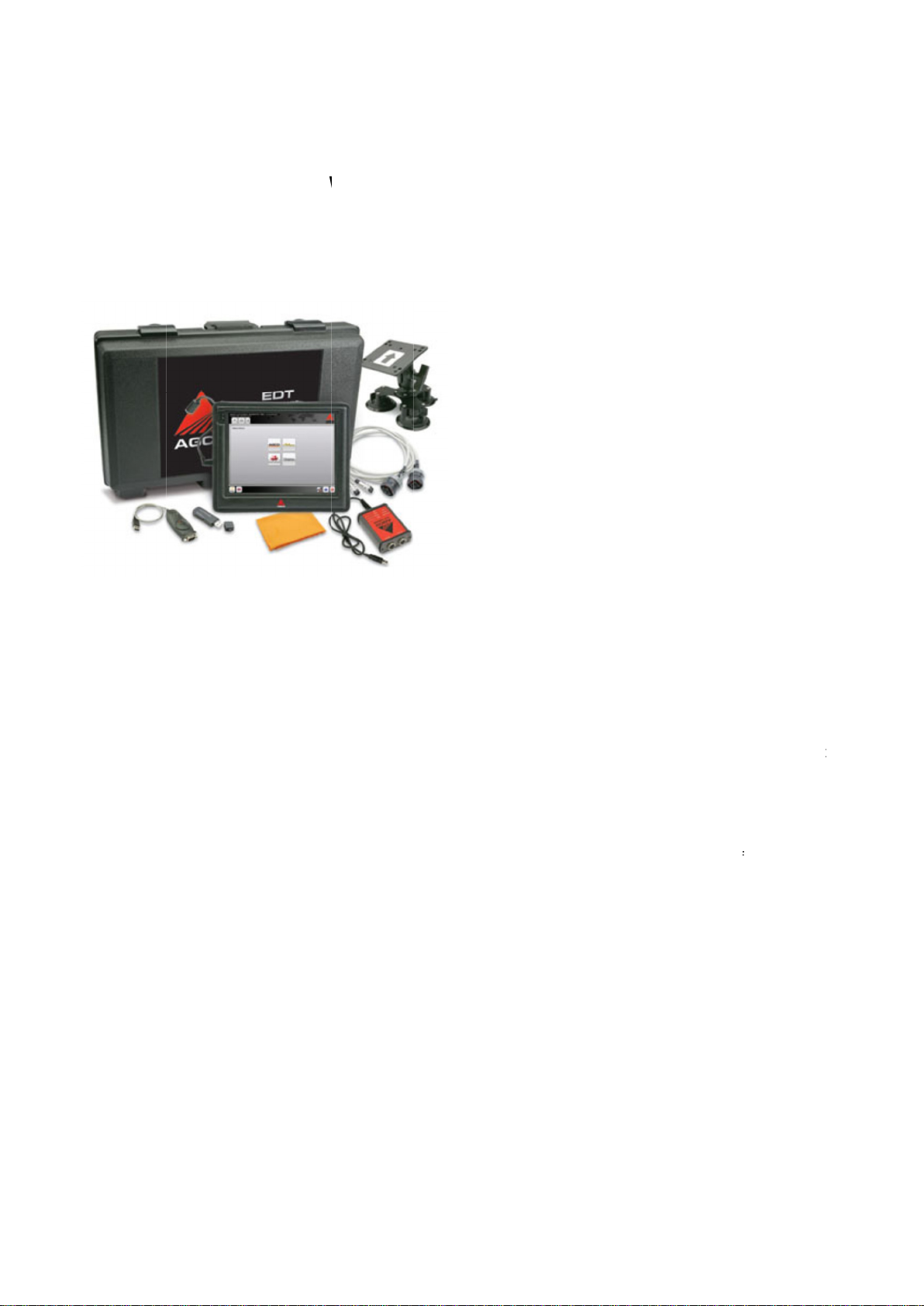
diagnostic tool kit that contains a diagnostic terminal, vehicle connection cables, CAN BUS
protocol adapter, carry case, and other items.
n of the EDT kit less the diagnostic terminal and associated parts is available. This kit will contain the EDT
software application, cables, and 2x4 CAN USB Protocol Adapter.
The annual software subscription fe
dealership sells that are supported by the dealership. Software subscription is not charged by
The annual subscription fee covers continual tool functional improvements, sof
support for the EDT (hardware and software issues) based on the type of EDT kit purchased. The subscription fee also
covers a loaner program for EDT kits purchased with a diagnostic terminal.
If the annual subscription is
expiration date, but eventually will become non
The EDT is used by dealership technicians to interface with specific machines that have a Cont
(CAN) BUS as part of the electronic system architecture.
diagnostic tool kit that contains a diagnostic terminal, vehicle connection cables, CAN BUS
protocol adapter, carry case, and other items.
n of the EDT kit less the diagnostic terminal and associated parts is available. This kit will contain the EDT
software application, cables, and 2x4 CAN USB Protocol Adapter.
The annual software subscription fe
e covers machine software updates for all AGCO brands and product lines the
dealership sells that are supported by the dealership. Software subscription is not charged by
The annual subscription fee covers continual tool functional improvements, sof
support for the EDT (hardware and software issues) based on the type of EDT kit purchased. The subscription fee also
covers a loaner program for EDT kits purchased with a diagnostic terminal.
If the annual subscription is
not renewed, the EDT application will work for a limited period of time after the renewal
expiration date, but eventually will become non
The EDT is used by dealership technicians to interface with specific machines that have a Cont
(CAN) BUS as part of the electronic system architecture.
diagnostic tool kit that contains a diagnostic terminal, vehicle connection cables, CAN BUS
protocol adapter, carry case, and other items.
n of the EDT kit less the diagnostic terminal and associated parts is available. This kit will contain the EDT
software application, cables, and 2x4 CAN USB Protocol Adapter.
e covers machine software updates for all AGCO brands and product lines the
dealership sells thatare supported bythe dealership. Software subscription is not charged by
The annual subscription fee covers continual tool functional improvements, sof
support for the EDT (hardware and software issues) based on the type of EDT kit purchased. The subscription fee also
covers a loaner program for EDT kits purchased with a diagnostic terminal.
not renewed, the EDT application will work for a limited period of time after the renewal
expiration date, but eventually will become non
-
functional (application will automatically lock).
The EDT is used by dealership technicians to interface with specific machines that have a Cont
(CAN) BUS as part of the electronic system architecture.
diagnostic tool kit that contains a diagnostic terminal, vehicle connection cables, CAN BUS
n of the EDT kit less the diagnostic terminal and associated parts is available. This kit will contain the EDT
software application, cables, and 2x4 CAN USB Protocol Adapter.
e covers machine software updates for all AGCO brands and product lines the
dealership sells that are supported by the dealership. Software subscription is not charged by
The annual subscription fee covers continual tool functional improvements, sof
support for the EDT (hardware and software issues) based on the type of EDT kit purchased. The subscription fee also
covers a loaner program for EDT kits purchased with a diagnostic terminal.
not renewed, the EDT application will work for a limited period of time after the renewal
functional (application will automaticallylock).
The EDT is used by dealership technicians to interface with specific machines that have a Cont
diagnostic tool kit that contains a diagnostic terminal, vehicle connection cables, CAN BUS
n of the EDT kit less the diagnostic terminal and associated parts is available. This kit will contain the EDT
software application, cables, and 2x4 CAN USB Protocol Adapter.
e covers machine software updates for all AGCO brands and product lines the
dealership sells thatare supported bythe dealership. Software subscription is not charged by
The annual subscription fee covers continual tool functional improvements, sof
support for the EDT (hardware and software issues) based on the type of EDT kit purchased. The subscription fee also
covers a loaner program for EDT kits purchased with a diagnostic terminal.
not renewed, the EDT application will work for a limited period of time after the renewal
functional (application will automatically lock).
The EDT is used by dealership technicians to interface with specific machines that have a Cont
diagnostic tool kit that contains a diagnostic terminal, vehicle connection cables, CAN BUS
n of the EDT kit less the diagnostic terminal and associated parts is available. This kit will contain the EDT
e covers machine software updates for all AGCO brands and product lines the
dealership sells that are supported by the dealership. Software subscription is not charged by
The annual subscription fee covers continual tool functional improvements, sof
tware update process and technical
support for the EDT (hardware and software issues) based on the type of EDT kit purchased. The subscription fee also
not renewed, the EDT application will work for a limited period of time after the renewal
functional (application will automaticallylock).
The EDT is used by dealership technicians to interface with specific machines that have a Cont
diagnostic tool kit that contains a diagnostic terminal, vehicle connection cables, CAN BUS
n of the EDT kit less the diagnostic terminal and associated parts is available. This kit will contain the EDT
e covers machine software updates for all AGCO brands and product lines the
dealership sells thatare supported bythe dealership. Software subscription is not charged by
-brand.
tware update process and technical
support for the EDT (hardware and software issues) based on the type of EDT kit purchased. The subscription fee also
not renewed, the EDT application will work for a limited period of time after the renewal
functional (application will automatically lock).
diagnostic tool kit that contains a diagnostic terminal, vehicle connection cables, CAN BUS
n of the EDT kit less the diagnostic terminal and associated parts is available. This kit will contain the EDT
e covers machine software updates for all AGCO brands and product lines the
tware update process and technical
support for the EDT (hardware and software issues) based on the type of EDT kit purchased. The subscription fee also
not renewed, the EDT application will work for a limited period of time after the renewal
5
diagnostic tool kit that contains a diagnostic terminal, vehicle connection cables, CAN BUS
n of the EDT kit less the diagnostic terminal and associated parts is available. This kit will contain the EDT
e covers machine software updates for all AGCO brands and product lines the
tware update process and technical
support for the EDT (hardware and software issues) based on the type of EDT kit purchased. The subscription fee also
not renewed, the EDT application will work for a limited period of time after the renewal