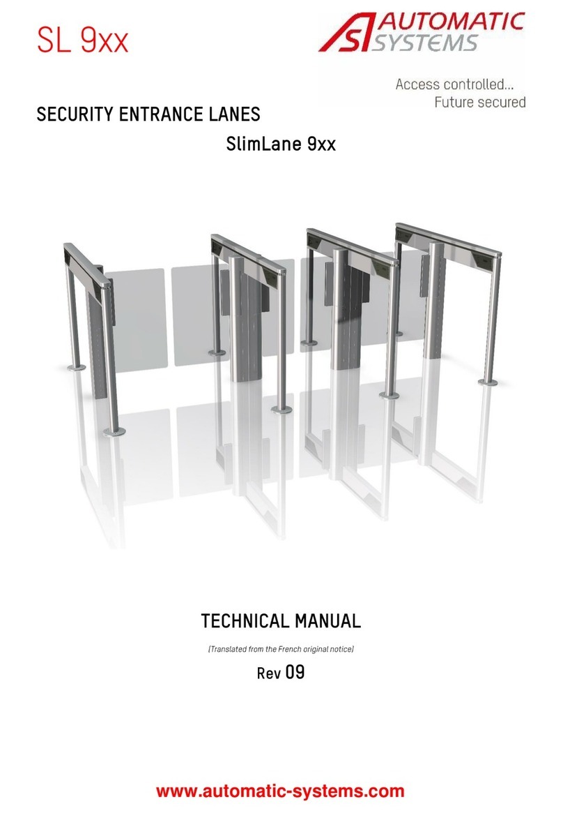
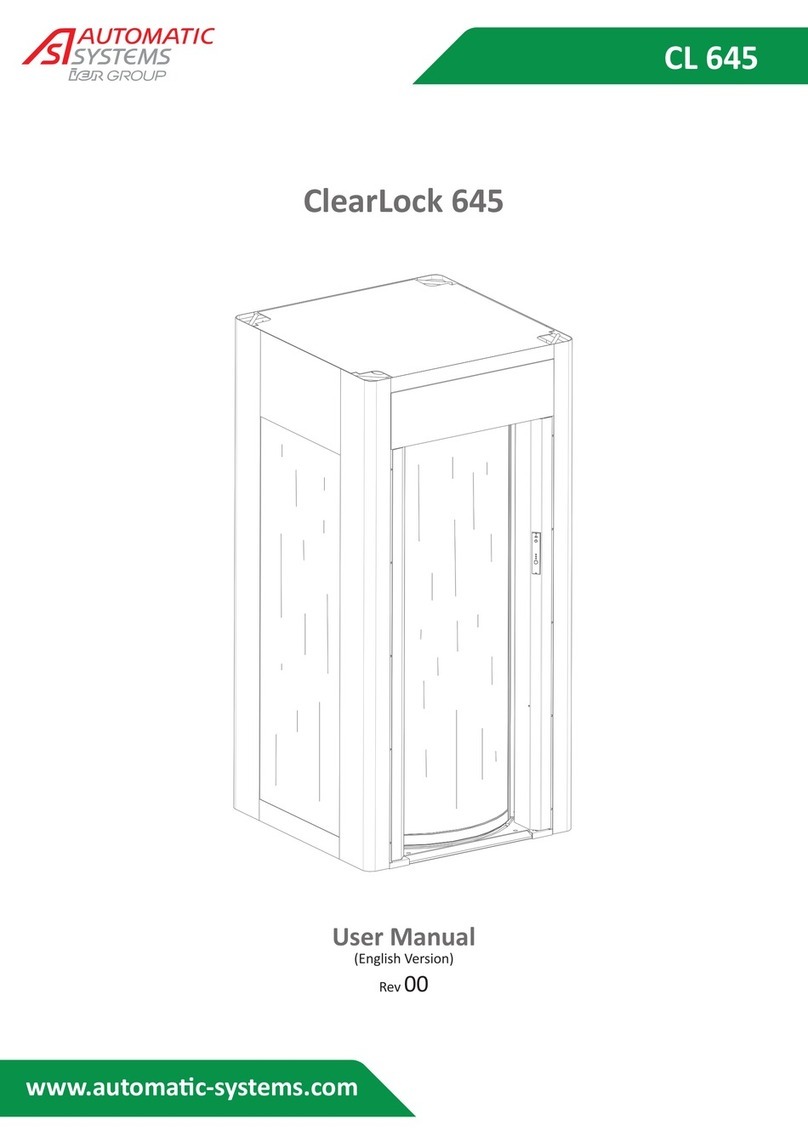
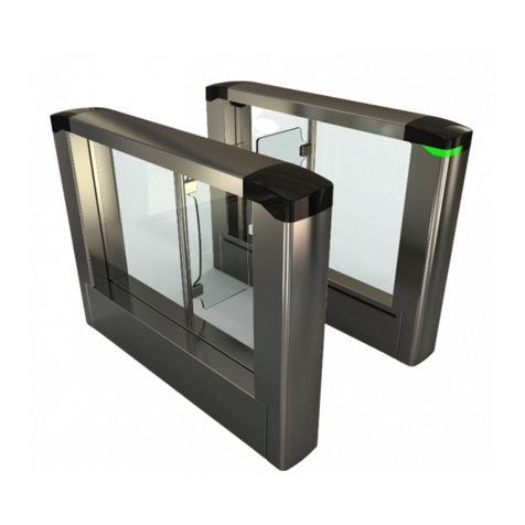
Automatic Systems ClearLock User manual

Security Booth
Technical Manual
NAM-CLEAR-MT-EN-A
The information contained in this document is the property of Automatic Systems
and is confidential. The recipient shall refrain from using it for any purpose other
than for the use of the products or the execution of the project to which it refers
and from communicating it to third parties without prior written agreement from
Automatic Systems. The document is subject to change without notice.
Security Booth
ClearLock
TECHNICAL MANUAL
Rev. A

2
Technical Manual
NAM-CLEAR-MT-EN-A
The information contained in this document is the property of Automatic Systems
and is confidential. The recipient shall refrain from using it for any purpose other
than for the use of the products or the execution of the project to which it refers
and from communicating it to third parties without prior written agreement from
Automatic Systems. The document is subject to change without notice.
Document Revision
Rev.
Date Written
by Checked
by Subject
A 2011-06-28 MFy MLB + JB First version

3
Technical Manual
NAM-CLEAR-MT-EN-A
The information contained in this document is the property of Automatic Systems
and is confidential. The recipient shall refrain from using it for any purpose other
than for the use of the products or the execution of the project to which it refers
and from communicating it to third parties without prior written agreement from
Automatic Systems. The document is subject to change without notice.
Table of Contents
1. SAFETY WARNINGS.....................................................................................................................................4
2. DESCRIPTION................................................................................................................................................5
2.1. COMPONENT LOCATION ...............................................................................................................................................................5
3. INSTALLATION..............................................................................................................................................7
3.1. SITE PREPARATION WORK............................................................................................................................................................7
3.2. STORAGE BEFORE INSTALLATION ................................................................................................................................................7
3.3. REQUIRED TOOLS........................................................................................................................................................................7
3.4. PACKING LIST..............................................................................................................................................................................8
3.5. EQUIPMENT ASSEMBLY (IF DELIVERED UNASSEMBLED)...............................................................................................................11
3.5.1. BASE ........................................................................................................................................................................11
3.5.2. UPRIGHTS .................................................................................................................................................................11
3.5.3. CANOPY....................................................................................................................................................................12
3.5.4. SIDE GLASS PANELS ..................................................................................................................................................14
3.5.5. MOBILE OBSTACLES ..................................................................................................................................................15
3.5.6. CEILING MOUNT.........................................................................................................................................................16
3.5.7. INSIDE COLUMN .........................................................................................................................................................17
3.5.8. METAL DETECTOR (OPTIONAL) ...................................................................................................................................18
3.6. EQUIPMENT INSTALLATION (ASSEMBLED)...................................................................................................................................19
3.7. ELECTRICAL CONNECTIONS .......................................................................................................................................................20
3.7.1. CONNECTIONS REQUIRED WHEN THE BOOTH IS DELIVERED UNASSEMBLED...................................................................20
3.7.2. EXTERNAL BOOTH CONNECTIONS ...............................................................................................................................22
3.8. START-UP .................................................................................................................................................................................24
4. OPERATION.................................................................................................................................................25
4.1. OPERATING PRINCIPLE ..............................................................................................................................................................25
4.2. PASSAGE AUTHORIZATION.........................................................................................................................................................26
4.3. MECHANICAL DRIVE SYSTEM......................................................................................................................................................26
4.4. OBSTACLE LOCKING AND UNLOCKING........................................................................................................................................27
4.5. EVACUATION MODE (EMERGENCY STOP) ....................................................................................................................................27
4.6. POWER FAILURE........................................................................................................................................................................27
4.7. SAFETY PHOTOCELLS................................................................................................................................................................27
4.8. NCD² CONTROL CONSOLE .........................................................................................................................................................28
4.8.1. CONSOLE DESCRIPTION.............................................................................................................................................29
4.8.2. CONSOLE PARAMETER PROGRAMMING .......................................................................................................................31
4.8.3. ALARM MESSAGES.....................................................................................................................................................33
4.8.4. OBSTACLE INITIALIZATION ..........................................................................................................................................34
4.9. PICTOGRAM ..............................................................................................................................................................................36
4.10. HEATER (OPTIONAL)................................................................................................................................................................36
5. MAINTENANCE............................................................................................................................................37
5.1. PREVENTIVE MAINTENANCE .......................................................................................................................................................37
5.2. PROBLEMS AND TROUBLESHOOTING (ALARMS) ..........................................................................................................................40
5.3. RECOMMENDED TIGHTENING TORQUES ......................................................................................................................................44
5.4. FIXED OBSTACLE REPLACEMENT................................................................................................................................................44
5.5. MOBILE OBSTACLE REPLACEMENT.............................................................................................................................................44
5.6. DOOR CLOSED POSITION ADJUSTMENT.......................................................................................................................................44
5.7. OBSTACLE LOCK ADJUSTMENT ..................................................................................................................................................45
5.8. SAFETY PHOTOCELL ADJUSTMENT (SEE ITEM 68 IN SECTION 2.1)................................................................................................45
5.9. ADJUSTMENT OF THE PRESENCE DETECTOR LOCATED INSIDE THE BOOTH ...................................................................................46
5.10. LEFT OBJECT DETECTOR ADJUSTMENT (OPTIONAL)..................................................................................................................46
5.11. NCD² CONSOLE CONFIGURATION.............................................................................................................................................47
5.12. SINGLE-PRESENCE DETECTION ADJUSTMENT (OPTIONAL).........................................................................................................48
5.13. METAL DETECTOR ADJUSTMENT (OPTIONAL)............................................................................................................................50
5.13.1. PROGRAMMING .......................................................................................................................................................52
5.14. PROLONGED STOP /DISPOSAL.................................................................................................................................................58
6. TECHNICAL SPECIFICATIONS..................................................................................................................59
7. DIMENSIONS ...............................................................................................................................................60
8. IMPLEMENTATION DRAWINGS.................................................................................................................61
9. WIRING DIAGRAM ......................................................................................................................................64
10. TERMINAL AND INPUT/OUTPUT ALLOCATION....................................................................................65

4
Technical Manual
NAM-CLEAR-MT-EN-A
The information contained in this document is the property of Automatic Systems
and is confidential. The recipient shall refrain from using it for any purpose other
than for the use of the products or the execution of the project to which it refers
and from communicating it to third parties without prior written agreement from
Automatic Systems. The document is subject to change without notice.
1. SAFETY WARNINGS
A number of safety precautions must be taken during the installation and
use of a Security Booth.
User safety
Do not cross the path of moving glass obstacles. The Security Booth is equipped with an unattended
operation feature. The glass obstacles could move unexpectedly.
DO NOT ENTER WHEN THE RED PICTOGRAM APPEARS. Only enter when you see the GREEN
PICTOGRAM.
Due to risk of injury, unaccompanied children must not be allowed to access the booth:
Children could place their hands on the obstacle before it is fully opened or has begun to open, and their
hands could be dragged along the obstacle and become pinched in the narrow gap of the unit.
Pets should not go through the booth.
Technical staff safety
Do not connect the equipment to a power source until instructed to do so. The Security Booth must be
installed with permanent wiring in accordance with the local code.
All equipment operations must be performed by qualified personnel. All operations that are not authorized
or that are carried out by an unqualified technician shall automatically and legally void the manufacturer’s
warranty and liability.
Ensure that the circuit breaker is turned off first before opening the housing of the Security Booth.
Keep the circuit breaker turned off for any work that does not require the motor or the programmable logic
controller to be turned on.
KEEP YOUR SECURITY BOOTH PROPERLY MAINTAINED as per manufacturer recommendations.
When servicing, keep the area around the Security Booth secured to avoid injuries from moving parts.
TO AVOID RISKS OF ELECTRICAL SHOCK, ensure that the Security Booth access panels are closed at
all times and only opened by trained personnel.
All internal elements that may be powered up or that may move must be handled with care.
Any modifications to the parameters must be performed by experienced and qualified personnel.
Automatic Systems is in no way responsible for any modifications made to the equipment. (Note: the
Security Booth is factory configured in “minimal risk” mode for its users.)
IMPORTANT SAFETY INSTRUCTIONS
TO REDUCE THE RISK OF INJURY OR DEATH, READ AND FOLLOW ALL SAFETY
INSTRUCTIONS BEFORE INSTALLING, OPERATING OR SERVICING THE SECURITY
BOOTH. SAVE THESE INSTRUCTIONS!

5
Technical Manual
NAM-CLEAR-MT-EN-A
The information contained in this document is the property of Automatic Systems
and is confidential. The recipient shall refrain from using it for any purpose other
than for the use of the products or the execution of the project to which it refers
and from communicating it to third parties without prior written agreement from
Automatic Systems. The document is subject to change without notice.
2. DESCRIPTION
2.1. Component location
61
Canopy containing the
control electronics and
the motorization
devices
67
Mobile obstacles (2)
(sliding doors)
62
Side glass panels (2)
64
Base
68
Safety photocells on
each side of the
obstacles
63
Button inside the booth
to unlock the entry door
(optional)
65
Intercom
(optional)
66
Function
pictogram
72
Lifting eye bolts
Non Secured Area (NSA)
(=Entry side)
Secured Area (SA)
(=Exit side)
71
Metal detector
(optional)

6
Technical Manual
NAM-CLEAR-MT-EN-A
The information contained in this document is the property of Automatic Systems
and is confidential. The recipient shall refrain from using it for any purpose other
than for the use of the products or the execution of the project to which it refers
and from communicating it to third parties without prior written agreement from
Automatic Systems. The document is subject to change without notice.
81
Infrared presence
detector inside the
booth 84
Left object detector
(optional)
83
Single-presence
volumetric detectors
(8)
(optional)
82
Keyed locking device to
lock the obstacle on the
entry side (NSA)
(optional)
80
LED lighting
94
Main board VB3406
96
Single-presence
detection
(optional)
95
Metal detector
(optional)
93
Obstacle motor
90
Electrical power supply
91
Backup batteries (2)
92
Speaker for voice
synthesizer
Non-secured area
Secured area 97
Door closed detector

7
Technical Manual
NAM-CLEAR-MT-EN-A
The information contained in this document is the property of Automatic Systems
and is confidential. The recipient shall refrain from using it for any purpose other
than for the use of the products or the execution of the project to which it refers
and from communicating it to third parties without prior written agreement from
Automatic Systems. The document is subject to change without notice.
3. INSTALLATION
3.1. Site preparation work
Prior to installation, preparation work must be performed in accordance with the implementation drawing (see
Chapter 8). The following requirement in particular must be met:
Booth installation and canopy maintenance require sufficient floor-to-ceiling height.
The ground must be able to sustain the pressure exerted by the equipment.
The ground must be perfectly flat (smooth).
The maximum tolerated floor inclination in all directions is 0.3% (¼ in over 6 ft 6 in [6 mm over 2 m]).
The slope must be constant (no direction change).
3.2. Storage before installation
Before installation, protect equipment from impact and store it in its original packaging in a dry area protected
from dust, heat and the weather.
Store between -22°F (-30°C) and 176°F (80°C).
3.3. Required tools
WARNING: Because the various components are heavy—the side glass panels, the doors and the canopy all
weigh more than 110 lb (50 kg) each—a minimum of 2 persons are required to assemble the equipment.
Device capable of lifting 880 to 2200 lb (400 to 1000 kg), if the equipment is delivered assembled
Lift truck to install the canopy (220 lb [100 kg]), if the equipment is delivered unassembled
10-ft (3-m) straps (2) or vacuum discs (4) to handle the glass panels
Safety footwear, gloves, helmet and goggles
Percussion drill and drill bit set (1/8 to 3/8-in [3 mm to 10 mm])
Flat, Phillips and Torx screwdriver sets
Step ladder (6 ft [2 m] high)
Metric 13-mm open-end wrench
Metric Allen key set
Pry bar
Flat file
Cutter
Flat nose pliers (8 in [200 mm])
Wire cutter
Caulking gun (silicone cartridge included)
Bubble level (12 in [30 cm] long)
Vacuum
Window cleaner
Stainless steel cleaner
Toweling paper
Masking tape

8
Technical Manual
NAM-CLEAR-MT-EN-A
The information contained in this document is the property of Automatic Systems
and is confidential. The recipient shall refrain from using it for any purpose other
than for the use of the products or the execution of the project to which it refers
and from communicating it to third parties without prior written agreement from
Automatic Systems. The document is subject to change without notice.
3.4. Packing list
If the booth is delivered unassembled:
Ref.
Qty Description Location (most of the screws are on the specified
component or assembly)
1 1 Base
2 1 Right upright NSA
3 1 Left upright NSA
4 1 Right upright SA
5 1 Left upright SA
6 1 Canopy
6a: Canopy with electronics
6b: Canopy cover – section 1
6c: Canopy cover – section 2
7 1 Ceiling mount with detectors
8 1 Right-side glass panel
8e: Glass panel bracing
8i: Glass panel bracing
9 1 Left-side glass panel
9e: Glass panel bracing
9i: Glass panel bracing
10 1 Mobile obstacle NSA
11 1 Mobile obstacle SA
12 1 Inside column
30 4 #5-M8 x 20 Flat socket cap screw 2, 3, 4, 5
31 8 #3-M5 x 10 Button socket cap screw 6a, 6b, 6c
32 4 #5-M8 x 20 Flat socket cap screw 6a, 2, 3, 4, 5
33 4 Ring 6a, 2, 3, 4, 5
34 sq Plastic shims 6a, 8, 9
35 3 Gray silicone cartridge 8, 9
36 12 M8 x 35 Hex cap screw (13-mm wrench) 6a, 10, 11
37 12 M8 Lock washer 6a, 10, 11
38 12 Nylon washer 6a, 10, 11
39 8 #4-M6 x 16 Button socket cap screw 6a, 7
40 10 #2.5-M4 x 10 Button socket cap screw 12
41 4 #4-M5 x 16 Socket cap screw 1, 6a, 12b
42 4 M5 Flat washer 1, 6a, 12b
43 4 M5 Lock washer 1, 6a, 12b
1 2
3
45
6a
6c
6b
7
8
9
10
11
8i
8e
12
9i
9e

9
Technical Manual
NAM-CLEAR-MT-EN-A
The information contained in this document is the property of Automatic Systems
and is confidential. The recipient shall refrain from using it for any purpose other
than for the use of the products or the execution of the project to which it refers
and from communicating it to third parties without prior written agreement from
Automatic Systems. The document is subject to change without notice.
Accessory box
50
Control console
2 keys (ref. APEM A126)
2 keys (ref. APEM 601)
160-ft (50-m) cable and 2 connectors
51
Intercom
160-ft (50-m) cable and a connector
52
Connector for standard power cable
115/230 VAC–24 VDC
53
Display for volumetric single-presence
detection
configuration (optional)

10
Technical Manual
NAM-CLEAR-MT-EN-A
The information contained in this document is the property of Automatic Systems
and is confidential. The recipient shall refrain from using it for any purpose other
than for the use of the products or the execution of the project to which it refers
and from communicating it to third parties without prior written agreement from
Automatic Systems. The document is subject to change without notice.
54 Metal detector programming terminal
Key
(optional)
55
Keys to manually lock the exterior obstacle
(optional)
4 lifting eye bolts

11
Technical Manual
NAM-CLEAR-MT-EN-A
The information contained in this document is the property of Automatic Systems
and is confidential. The recipient shall refrain from using it for any purpose other
than for the use of the products or the execution of the project to which it refers
and from communicating it to third parties without prior written agreement from
Automatic Systems. The document is subject to change without notice.
3.5. Equipment assembly (if delivered unassembled)
Installation work must be done in accordance with the safety warnings (see Chapter 1).
3.5.1. Base
1. Lay down the base (1) (approximately 110 lb [50 kg]):
Ensure the rubber side is facing up;
Ensure the base is properly aligned with respect to passage direction; use the tracks as
a reference point to determine where the obstacles should stop in a closed position.
Note: The base is symmetric and does not need to be oriented with respect to the
secured and non-secured areas.
3.5.2. Uprights
1. Remove the screw (30) from the base support (1).
2. Install the upright (4) on the support.
3. Fasten the upright (4) to the support with the screw (30).
4. Repeat the previous steps for the 3 other uprights (2, 3 and 5).
1
4
Support
30
1
45
2
3
Support Support
Support Support
Secured
area
1
Non-secured
area
Direction of passage
Obstacle
stops

12
Technical Manual
NAM-CLEAR-MT-EN-A
The information contained in this document is the property of Automatic Systems
and is confidential. The recipient shall refrain from using it for any purpose other
than for the use of the products or the execution of the project to which it refers
and from communicating it to third parties without prior written agreement from
Automatic Systems. The document is subject to change without notice.
3.5.3. Canopy
1. Remove the screws (31) and the covers (6b
and 6c) from the canopy (6a).
Note: Covers of booths with wider diameters
have 3 sections.
2. Remove the screws (32) from the uprights (2,
3, 4, 5) and remove the rings (33).
4
33
32
3
1
6a
6b
6c

13
Technical Manual
NAM-CLEAR-MT-EN-A
The information contained in this document is the property of Automatic Systems
and is confidential. The recipient shall refrain from using it for any purpose other
than for the use of the products or the execution of the project to which it refers
and from communicating it to third parties without prior written agreement from
Automatic Systems. The document is subject to change without notice.
3. Fasten the 4 M16 lifting eye bolts to the
canopy (6a) (approximate canopy weight is
220 lb [100 kg]).
Install the canopy on the uprights (2, 3, 4, 5)
in the proper orientation: electrical power on
the non-secured side.
4. Loosely fasten the canopy (so the side glass
panels can be installed) to the uprights using
the rings (33) and the screws (32).
5. Install the covers only after running the
electric cables (see section 3.7).
4
6a
33
32
Non-secured area
Secured area
45
2
3
6a

14
Technical Manual
NAM-CLEAR-MT-EN-A
The information contained in this document is the property of Automatic Systems
and is confidential. The recipient shall refrain from using it for any purpose other
than for the use of the products or the execution of the project to which it refers
and from communicating it to third parties without prior written agreement from
Automatic Systems. The document is subject to change without notice.
3.5.4. Side glass panels
WARNING: The glass panels weigh more than
110 lb (50 kg) and must be handled by 2 or more
persons with the help of vacuum discs and/or
straps.
1. Loosen the 2 screws (30) of the upright (3).
2. Turn the upright (3) to insert the glass panel
more easily; to do so, loosen the screw (32)
holding the canopy (6a) to the upright (3).
3. Install 2 rubber patches on the base as well
as on the uprights to prevent the glass from
touching the metal.
4. Insert the glass panel (9) (weight > 110 lb
[50 kg]) in the upright (4).
5. Insert the glass panel (9) in the upright (3)
and pivot the upright to return it to its initial
direction.
6. Tighten the screws (30 and 32).
7. Center the glass panel (9) between the
2 uprights (3 and 4).
8. Install shims (34) between the glass panel (9)
and the canopy (6a) to lock the panel in place;
ensure the panel remains plumb.
9. Repeat the previous steps for the other side
glass panel (8).
10. Cut the rubber patches so they are flush with
the glass panels, and apply a silicone joint in
the spaces between the glass panels (8 and
9), the canopy (6a) and the uprights (2, 3, 4,
5).
11. Use silicone to adhere the braces (8e, 9e, 8i,
9i) between the glass panels and the canopy.
Hold the braces in place with masking tape
until the silicone sets.
Note: Apply the silicone. Allow 24 hours to dry before using the booth. Clean any silicone residue once dried.
30
30
Pivot the
u
p
ri
g
ht
Insert the glass
panel in the
upright
4 5
2
3
6a
1
9
3
6a
33
32
4
3
9
6a
9i
9e
S
p
ace
S
p
ace
S
p
ace
34 34
4
3
9
6a

15
Technical Manual
NAM-CLEAR-MT-EN-A
The information contained in this document is the property of Automatic Systems
and is confidential. The recipient shall refrain from using it for any purpose other
than for the use of the products or the execution of the project to which it refers
and from communicating it to third parties without prior written agreement from
Automatic Systems. The document is subject to change without notice.
3.5.5. Mobile obstacles
WARNING: The mobile obstacles weigh more than 110 lb (50 kg) and must be handled by at least 2
persons with the help of vacuum discs and/or straps.
1. Insert the lower wheels of the door
into the bottom track of the base,
then tilt the door back into an
upright position.
2. Set the 2 upper wheels on the
guide rail.
3. Adjust the door on its supports so
that:
The door is plumb and aligned
with the uprights.
There is no contact between the
lower wheels of the door and the
bottom track of the base (there
should be a 0.080- to 0.125-in
(2- to 3-mm space).
The door does not touch the
ceiling mount once installed.
The door slides freely
throughout its entire rotation.
The lower wheel is only slightly
touching the guide rail.
4. Adjust the rack on the supports so
there is a small gap between the
rack and the pinion.
5. Repeat the previous steps for the
second door.
Rack
Pinion Rack attachment
on supports
Upper wheel
Lower wheel
Guide rail
Door support
A
djustment nuts
A
A
B
A- Door height
adjustment
B- Loosen to adjust the
distance between the
door and the fixed side
glass panel.
Bottom track
Lower wheel

16
Technical Manual
NAM-CLEAR-MT-EN-A
The information contained in this document is the property of Automatic Systems
and is confidential. The recipient shall refrain from using it for any purpose other
than for the use of the products or the execution of the project to which it refers
and from communicating it to third parties without prior written agreement from
Automatic Systems. The document is subject to change without notice.
3.5.6. Ceiling mount
1. Remove the screws (39) from the
canopy (6a) braces.
2. Tilt the ceiling mount to insert it under
the canopy. Center it over the braces.
3. Fasten the ceiling mount (7) to the
canopy braces with the screws (39).
6a
39
6a
7
39
7

17
Technical Manual
NAM-CLEAR-MT-EN-A
The information contained in this document is the property of Automatic Systems
and is confidential. The recipient shall refrain from using it for any purpose other
than for the use of the products or the execution of the project to which it refers
and from communicating it to third parties without prior written agreement from
Automatic Systems. The document is subject to change without notice.
3.5.7. Inside column
1. Remove the screws (40) and the cover (12a) of the column (12b).
2. Remove the screws and washers (41, 42 and 43) from the ceiling mount (7) and the base (1).
3. Position the column (12b) between the ceiling mount (7) and the base (1).
Note: Run the cable (if any) through the hole in the ceiling mount.
4. Fasten the column (12b) to the ceiling mount (7) and the corner bracket (12c) of the base (1) with the
screws and washers (41, 42 and 43).
5. Fasten the cover (12a) to the column (12b) with the screws (40).
12a
12b
7
5
40
41
42
43
43
42
41
Run the cable through
the hole in the ceiling
12b
1
5
12c
41
42
43
12b
7
5
43
42
41
12c 1
5

18
Technical Manual
NAM-CLEAR-MT-EN-A
The information contained in this document is the property of Automatic Systems
and is confidential. The recipient shall refrain from using it for any purpose other
than for the use of the products or the execution of the project to which it refers
and from communicating it to third parties without prior written agreement from
Automatic Systems. The document is subject to change without notice.
3.5.8. Metal detector (optional)
Note: The operation of the metal detector can be hindered by:
Devices generating electromagnetic fields or vibrations:
- Underground or overhead power lines
- Transformers
- Radio transmitters
- Fluorescent lamps
- Elevators
- Air conditioners
- Monitors, television sets
- Change machines
- Revolving doors
Metal structures in the surrounding area (e.g., beams, suspended ceilings or floating floors)
It is also imperative to prevent contact with all metal components.
Assembly:
With the bolts provided, attach the 2 antennas on both sides of the entry door (with respect to the
orientation).
Connect the cables to the metal detector board (see section 3.7.1).
Left side:
Transmitter
(red sleeve)
Right side:
Receiver
(black sleeve)
Cable through-hole
M6 x 30 (4)
M8 x 16 (2)

19
Technical Manual
NAM-CLEAR-MT-EN-A
The information contained in this document is the property of Automatic Systems
and is confidential. The recipient shall refrain from using it for any purpose other
than for the use of the products or the execution of the project to which it refers
and from communicating it to third parties without prior written agreement from
Automatic Systems. The document is subject to change without notice.
3.6. Equipment installation (assembled)
- Bring the booth to its location (booth weight is indicated in Chapter 6) with a device such as a crane,
a pallet truck, cylinders, etc. (not included).
- Position the booth correctly, i.e., with the electrical power on the non-secured side.
- If the equipment comes with the optional metal detector, then the equipment must be insulated
from all other metal components.
If the floor is metal, use a rubber mat between the floor and the booth and between the floor and the
antennas of the metal detector.
- Adjust the level of the booth by inserting shims under the base at the floor attachment points, where
required.
- To access the booth's floor attachment points, the obstacles can be manually moved.
If required, pull on the rod of the electromagnetic lock to free the door (the electromagnetic lock can
be accessed via the canopy cover).
- Bolt the equipment to the floor with 4 anchors that are a maximum of 5/16 in (8 mm) in diameter.
oThe equipment must be bolted to the ground before being used.
oThe methods and procedure used to bolt the equipment to the ground must be adapted
based on the environment and the nature of the ground on which it will be bolted.
oThe work must also be validated by a professionally qualified engineer.
oAutomatic Systems cannot be held responsible for any accident or damage caused to the
equipment due to improper floor attachment.
- Clean the glass panels and the base of the booth.
- Remove the protection film from the lights.
Non-secured area
Secured area
Electrical powe
r

20
Technical Manual
NAM-CLEAR-MT-EN-A
The information contained in this document is the property of Automatic Systems
and is confidential. The recipient shall refrain from using it for any purpose other
than for the use of the products or the execution of the project to which it refers
and from communicating it to third parties without prior written agreement from
Automatic Systems. The document is subject to change without notice.
3.7. Electrical connections
WARNING: All tasks must be performed in accordance with the safety warnings (see Chapter 1). In
particular, electrical power must be cut before performing the tasks described below.
Note: Connections must be done in accordance with the wiring diagrams included inside the equipment,
as these represent the primary reference instructions.
3.7.1. Connections required when the booth is delivered unassembled
Safety photocells (see item 68 in section 2.1)
Connect both parts of the 4 connectors (50).
Hold the cables in place with a collar so door movement is not hindered.
Emergency stop
Connect the emergency stop button (see item 63
in section 2.1) of the inside column to the
connector (MM01) located inside the canopy.
Follow the wire color coding.
Canopy components
Connect both parts of the connector (MM02) to link
the canopy components (lights, optional detectors,
etc.) to the electronic board.
MM02
MM01
Collar
50
50
50
50
50
Table of contents
Other Automatic Systems Security System manuals
Popular Security System manuals by other brands

Advent
Advent home navigator user guide

Arlec
Arlec AM 500 Installation & operating instructions

First Alert
First Alert FA168C Programming guide

Bay Alarm Medical
Bay Alarm Medical In-Home Medical quick start guide

NUUO
NUUO G3 Card Hardware & software installation

Target
Target DCMA-4000-ANZ instruction manual