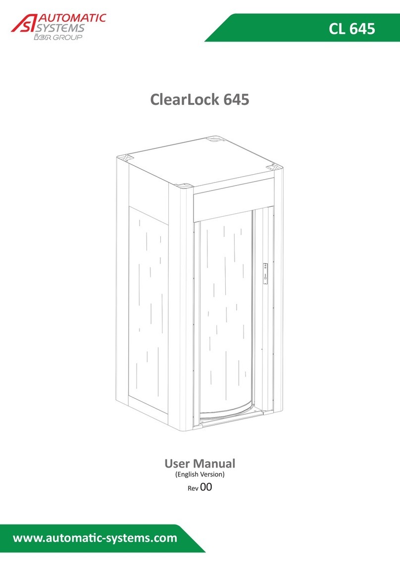
Automatic Systems ClearLock 645 User manual

CL 645
www.automac-systems.com
ClearLock 645
Technical Manual
(English Version)
Rev 00

The information contained in this document is the property of Automatic Systems and is confidential. The recipient shall refrain from using this information for any purpose other
than the use of the products or the execution of the project to which it refers and from communicating it to third parties without prior written agreement of Automatic Systems.
The document is subject to change without notice.
ClearLock 645-TM-EN p. 2 / 44
DOCUMENT REVISION
Rev. Date Writer Checked by Subject
00 11/2015 SLu

The information contained in this document is the property of Automatic Systems and is confidential. The recipient shall refrain from using this information for any purpose other
than the use of the products or the execution of the project to which it refers and from communicating it to third parties without prior written agreement of Automatic Systems.
The document is subject to change without notice.
ClearLock 645-TM-EN p. 3 / 44
TABLE OF CONTENTS
1. SAFETY WARNINGS...................................................................................................................... 4
2. STRUCTURE AND COMPONENTS................................................................................................. 5
2.1. .................................................................................................... 5
2.2. ..................................................................................................................................... 6
2.3. .......................................................................................................................... 7
2.4. ......................................................................................................... 8
2.5. .......................................................................................................................... 9
2.6. ....................................................................................................... 10
2.7. ........................................................................................................... 11
2.8. ............................................................................................................... 12
2.9. .......................................................................................................... 13
2.10. ........................................................................................................................ 14
3. ELECTRONIC MAIN BOARD........................................................................................................ 15
3.1. ..................................................................................................................... 16
3.2. ......................................................................................................................................... 17
3.3. ........................................................................................................................................... 18
3.4. ...................................................................................................................... 19
3.5. .............................................................................................................. 26
3.6. ......................................................................................... 27
3.7. ................................................................................................... 28
4. PROGRAMMING AND DIAGNOSTICS........................................................................................ 29
5. CHANGING COMPONENTS ........................................................................................................ 30
5.1. .......................................................................................................................................................... 30
5.2. ................................................................................................................... 31
5.3. ............................................................................................................ 32
5.4. ..................................................................................................................................... 33
5.5. ................................................................................................................................ 34
5.6. ............................................................................................................. 35
5.7. ............................................................................................................................................. 36
5.8. ................................................................................................................................................... 38
5.9. ................................................................................................................................ 39
5.10. .............................................................................................................. 40
6. FUNCTION ANOMALIES............................................................................................................. 42
6.1. .......................................................................... 43
6.2. ........................................................................................ 43

The information contained in this document is the property of Automatic Systems and is confidential. The recipient shall refrain from using this information for any purpose other
than the use of the products or the execution of the project to which it refers and from communicating it to third parties without prior written agreement of Automatic Systems.
The document is subject to change without notice.
ClearLock 645-TM-EN p. 4 / 44
PLACING AND MAINTENANCE
This handbook must be used only by qualied technicians and authorised by Automac Systems
1. Safety warnings
This manual must be made available to any person who works with the equipment, e.g., installers,
maintenance technicians, end users, etc.
to any other use without risk to users or to the integrity of the equipment.
Automac Systems cannot be held responsible for damages caused by improper use of the equipment.
It is strongly recommended that children be supervised as they pass through the door.
Extreme care is also required with animals, which should be kept on a leash and under the control of
their owners.
The Contractor shall comply with local standards when installing the equipment.
Automac Systems shall reserve the
technician is performed on this product.
Access to the mechanism is reserved for personnel who are aware of the electrical and mechanical dangers
power using the SYSTEM switch on the console ð OFF
AND
the part of Automac Systems.
Especially for booth product:
not walk on the booth’s roof.
Before moving the booth make sure that the weight basket is anchored to the casing with the blocking
system.
There is a small internal panel where the main switch can be accessed and the security system can be
adjusted.
clean place.

The information contained in this document is the property of Automatic Systems and is confidential. The recipient shall refrain from using this information for any purpose other
than the use of the products or the execution of the project to which it refers and from communicating it to third parties without prior written agreement of Automatic Systems.
The document is subject to change without notice.
ClearLock 645-TM-EN p. 5 / 44
2. STRUCTURE AND COMPONENTS
2.1. Main switch and on switch
Table 01
4
3
1
25
6
Inside view with open inspecon panel
1) Booth’s ON/OFF switch
2)
3) Switch 220 V.
4)
5)
6)

The information contained in this document is the property of Automatic Systems and is confidential. The recipient shall refrain from using this information for any purpose other
than the use of the products or the execution of the project to which it refers and from communicating it to third parties without prior written agreement of Automatic Systems.
The document is subject to change without notice.
ClearLock 645-TM-EN p. 6 / 44
2.2. Top view
Table 02
Internal
1
23
9
5
6
7
8
10
11
12
13
15
14
10
16
17
18
4
External

The information contained in this document is the property of Automatic Systems and is confidential. The recipient shall refrain from using this information for any purpose other
than the use of the products or the execution of the project to which it refers and from communicating it to third parties without prior written agreement of Automatic Systems.
The document is subject to change without notice.
ClearLock 645-TM-EN p. 7 / 44
2.3. Components list table 02
Rep. Parculars Qty. Code
1 Main board 1 5205305
2 Power supply 1 5205727
3 1 5205078
4 2 350789364
5 Reducer 2 5005904
6 Loading Cell 1 509T500
7 Motor 2 5105226
8 Encoder 2 5206032
5+7+8 Motor reducer group 2 5105903
9 1 5206089
10 2 440205605R1
11 Speaker 1 5805868
12 1
13 Mechanical lock 1 5300961
14 Mechanical lock Micro switch 1 5200067
15 Mechanical lock cylinder 1 5303656
16 1 5207391
17 1 5207851
18 2 50982A12V

The information contained in this document is the property of Automatic Systems and is confidential. The recipient shall refrain from using this information for any purpose other
than the use of the products or the execution of the project to which it refers and from communicating it to third parties without prior written agreement of Automatic Systems.
The document is subject to change without notice.
ClearLock 645-TM-EN p. 8 / 44
2.4. Secon design main view
Table 03
1
2
3
9
5
6
7
8
11
12
13
23
25
24
15
14
10
20
21
22
16 17
18
18
4
19
External

The information contained in this document is the property of Automatic Systems and is confidential. The recipient shall refrain from using this information for any purpose other
than the use of the products or the execution of the project to which it refers and from communicating it to third parties without prior written agreement of Automatic Systems.
The document is subject to change without notice.
ClearLock 645-TM-EN p. 9 / 44
2.5. Components list table 03
Rep. Parculars Qty. Code
1 Main board 1 5205305
2 Power supply 1 5205727
3 2 50982A12V
4 Long leaf Spring 2 4401124
5 1 5205078
6 1 5206089
7 Speaker 1 5805868
8 1
9 1 410586364
10 1 5205306
11 1
12 1
13 Unmarked panels 1 4101794
14 Leaf spring support 4 4401518
15 Short leaf spring 2 4400861
16 Mechanical lock 1 5300961
17 Mechanical lock cylinder 1 5303656
18 2 350789364
19 1 5207851
20 2 Pairs 5204239
21 Magnets 4 4400267
22 1 5207151
23 1 5207152
24 1 5207391
25 Mechanical lock Micro switch 1 5200067

The information contained in this document is the property of Automatic Systems and is confidential. The recipient shall refrain from using this information for any purpose other
than the use of the products or the execution of the project to which it refers and from communicating it to third parties without prior written agreement of Automatic Systems.
The document is subject to change without notice.
ClearLock 645-TM-EN p. 10 / 44
2.6. Internal Secon diagram
Table 04
2
3
4
5
1
Internal

The information contained in this document is the property of Automatic Systems and is confidential. The recipient shall refrain from using this information for any purpose other
than the use of the products or the execution of the project to which it refers and from communicating it to third parties without prior written agreement of Automatic Systems.
The document is subject to change without notice.
ClearLock 645-TM-EN p. 11 / 44
2.7. Weight Internal space
Table 05
1
1
2
2
3
3
3
3
9
5
6
7
8
11
12
13
13
14
10
4
Internal
External
15

The information contained in this document is the property of Automatic Systems and is confidential. The recipient shall refrain from using this information for any purpose other
than the use of the products or the execution of the project to which it refers and from communicating it to third parties without prior written agreement of Automatic Systems.
The document is subject to change without notice.
ClearLock 645-TM-EN p. 12 / 44
2.8. Components list table 04
Rep. Parculars Qty. Code
1 Unmarked panels 1 3504267
2 1 350586564
3 1 5205307
4 2 Pairs 5204239
5 Magnets 4 4400267
2.9. Components list table 05
Rep. Parculars Qty. Code
1 Nylon bolt M16 H15 12 5400519
2 Assembled door 2 230698664
3 4 4401070
4 4 4302523
5 1 2202007
6 1 2207304
7 1 440719064
8A
Glass basket wall 1 430756764
8B Unmarked basket wall 1 430756864
9 Phenol basket panel 2 440717964
10 1 4401957
11
Basket iron stanchion 1 350717764
12
Basket side CE iron stanchion 1 350717864
13
4 4300518
14 Screw M 8
15A Basket side glass wall CE 1 430726864
15B Unmarked basket wall sideCE
1 430726964

The information contained in this document is the property of Automatic Systems and is confidential. The recipient shall refrain from using this information for any purpose other
than the use of the products or the execution of the project to which it refers and from communicating it to third parties without prior written agreement of Automatic Systems.
The document is subject to change without notice.
ClearLock 645-TM-EN p. 13 / 44
2.10. Mechanical Movement
Table 06
19 18
17
14
13
12
11 10
9
8
7
6
4
3
2
5
1
22
23
26
24
25
20
21
16
15

The information contained in this document is the property of Automatic Systems and is confidential. The recipient shall refrain from using this information for any purpose other
than the use of the products or the execution of the project to which it refers and from communicating it to third parties without prior written agreement of Automatic Systems.
The document is subject to change without notice.
ClearLock 645-TM-EN p. 14 / 44
2.11. Components list table 06
Rep. Parculars Qty. Code
1 1 4401957
2 Top hub spacer ring 1 4302624
3 1 4402588
4 Top hub spacer ring 1 4302623
5 Basket ceiling 1 440719164
6 Carrier wheel pin 4 4302531
7 Carrier wheel 4 504117100
8 Carrier 2 440818794R2
9 Unblocking door spring 2 4402653
10 2 5105867
11 1 4402587
12 Pin parts to move carrier 2 2209307
13 2 2209308
14 Proximity Sensor 2 5092PNO
15 Encoder 2 5206032
16 Motor 2 5108258
17 Reducer 2 5008150
18 Motor reducer group 2 5108259
19 Proximity small reading square 2 350844394
20 Loading Cell 1 509T500
21 Motor reducer support 1 350818394R1
22 2 350818894
23 2 350818194
24 Light 2 5801285
25 Light bulb 1 50912V10W
26 Cam. 2 430667964R3

The information contained in this document is the property of Automatic Systems and is confidential. The recipient shall refrain from using this information for any purpose other
than the use of the products or the execution of the project to which it refers and from communicating it to third parties without prior written agreement of Automatic Systems.
The document is subject to change without notice.
ClearLock 645-TM-EN p. 15 / 44
3. ELECTRONIC MAIN BOARD
Rearma-
ment
INT. Motor
OUTPUTS
INTPUTS
Inputs power
supply
Magnet
TEST
Console 1
Loading cell
Console 2
Line 1
Line 2
Main light
INT. Proximity switch
INT. Photocells
INT. Encoder
Unblock
A
B
OFF
ON
INT.
Metal
1
21
5
4
6
8
24
17
18
16
22
23
19
2
7
3
10
11
12
13
14
15
20
9

The information contained in this document is the property of Automatic Systems and is confidential. The recipient shall refrain from using this information for any purpose other
than the use of the products or the execution of the project to which it refers and from communicating it to third parties without prior written agreement of Automatic Systems.
The document is subject to change without notice.
ClearLock 645-TM-EN p. 16 / 44
3.1. Connecons to main board
A Booth’s ON/OFF switch.
B
1
2
3
4
5
6
7
8
9
10
11
12
13
14
15
16
17
18
19
20
clamps 4 and 8 unblocked ext. door.
clamps 4 and 9 unblocked int. door.
21
22
23
24

The information contained in this document is the property of Automatic Systems and is confidential. The recipient shall refrain from using this information for any purpose other
than the use of the products or the execution of the project to which it refers and from communicating it to third parties without prior written agreement of Automatic Systems.
The document is subject to change without notice.
ClearLock 645-TM-EN p. 17 / 44
3.2. Block diagram
Unblock
310cv14A
Console
310cv19A
Power supply
310cv08A
310cv12A
Metal detector
5808022
I/O 315 Board
310cv17A External rubber side
310cv18A Internal rubber side
310cv03A
5806791 SUN System
310cv09A
Mechanical lock
Spotlight
310cv13A
310cv24B Unblocked
int. door
External magnet
310cv07A
310cv24A
Internal magnet
310cv07B
Unblocked
ext. door
Loading cell
External motor 310cv01A
External proximity switch cv10A
310cv04A
External encoder
Speaker 310cv06A
Internal motor
310cv02A
5806791 Metal detector
(with digital console)
Internal proximity switch
cv11A
Internal encoder
310cv05A
310cv14A Intercom’s call

The information contained in this document is the property of Automatic Systems and is confidential. The recipient shall refrain from using this information for any purpose other
than the use of the products or the execution of the project to which it refers and from communicating it to third parties without prior written agreement of Automatic Systems.
The document is subject to change without notice.
ClearLock 645-TM-EN p. 18 / 44
3.3. Power Supply
3.3.1. Back view
Power supply 220V
10A FUSE
Main switch
3.3.2. Side back view
+24V +24V
+24V
Line connected

The information contained in this document is the property of Automatic Systems and is confidential. The recipient shall refrain from using this information for any purpose other
than the use of the products or the execution of the project to which it refers and from communicating it to third parties without prior written agreement of Automatic Systems.
The document is subject to change without notice.
ClearLock 645-TM-EN p. 19 / 44
3.4. Connecons (main board)
3.4.1. Motors
3.4.1.1. Internal door motor 3.4.1.2. External door motor
MOTOR POWER SUPPLY MOTOR POWER SUPPLY
Green/Black Green/Black
MOTOR POWER SUPPLY MOTOR POWER SUPPLY
Cable/colour motor connecon chart
MOTOR
INTERNAL
BOOTH
1 BROWN
3 WHITE
1 BROWN
3 WHITE
LEFT 1 BROWN
3 WHITE
1 WHITE
3 BROWN
RIGHT 1 BROWN
3 WHITE
1 WHITE
3 BROWN
3.4.1.3. Baeries 3.4.1.4. Int. magnet 3.4.1.5. Ext. magnet
+24V +24V
Red White White
111
222
+24V
Black Brown Brown

The information contained in this document is the property of Automatic Systems and is confidential. The recipient shall refrain from using this information for any purpose other
than the use of the products or the execution of the project to which it refers and from communicating it to third parties without prior written agreement of Automatic Systems.
The document is subject to change without notice.
ClearLock 645-TM-EN p. 20 / 44
3.4.1.6. Ceiling light
Green PORTER
Yellow PORTER
White PORTER Brown PORTER
LIGHT POWER SUPPLY
White
1
5
2
6
3
7
4
8
Black
White Red
White
Red Red
+ SPEAKER
(INTER. BUTTON) V+ LIGHT POWER SUPPLY
INTERCOM BUTTON
3.4.1.7. Power supply
+ 24 V 5 1
6 2
7 3
8 4
+ 24 V
BATTERY POWER CHECK + 24 V
POWER PRESENCE
3.4.1.8. Metal Detector
+ 24 V
15 26 37 48
Power supply
for emergency
exit EMPLC1
+ 12 V
L I -
L I +
Other manuals for ClearLock 645
1
This manual suits for next models
1
Table of contents
Other Automatic Systems Security System manuals
Popular Security System manuals by other brands

Advent
Advent home navigator user guide

Arlec
Arlec AM 500 Installation & operating instructions

First Alert
First Alert FA168C Programming guide

Bay Alarm Medical
Bay Alarm Medical In-Home Medical quick start guide

NUUO
NUUO G3 Card Hardware & software installation

Target
Target DCMA-4000-ANZ instruction manual