Automatic LPE 500 User manual

Page 1 of 26 7/9/19
LPE 500 & LPE 700
LOW PROFILE ELECTRIC
STATIONARY ROLLER MILL
Operator, Parts &
Installation Manual

Page 2 of 26 7/9/19
Exchange & Resharpening Roll Service
If your rolls ever become dull or require resharpening, you can order an exchange set of rolls. For further
details on our special roll replacement program, contact your nearest dealer or distributor. If you do not
have a dealer or distributor in your area, contact the factory. Credit allowance on used rolls is subject to roll
inspection upon return to factory via prepaid freight.
Introduction
Congratulations! You are now the owner/operator of America’s finest roller mill. Please take a few minutes to
be sure that you understand the maintenance and operation of this roller mill. Read this operator’s manual
carefully: you’ll get better results and have fewer problems.
After your roller mill has been in operation for a few hours, check for loose bolts, setscrews, belts, etc.
All are tight when the roller mill leaves the factory; however, after a break-in period, some items may
require additional tightening. Like any other machine, your Automatic roller mill requires proper care and
intelligence in operation. Misuse and neglect will only cause unnecessary expense and dissatisfaction.
This manual is written as a guide for owners and operators of the Automatic LPE500 & LPE700 model roller
mill. Read it carefully and follow the suggestions made. Keep this manual in a convenient place for quick,
easy reference, and use it whenever questions arise.
Fill in the following information now for future reference and convenience. Always give this information
to your dealer when ordering new parts. If at any time it becomes necessary for you to write directly to
Automatic Equipment Manufacturing Company for additional information, give the model and serial number
of your machine, and as much descriptive information as possible. It will enable us to more thoroughly and
quickly expedite your order.
Model No. _____________________ Serial No. _____________________ Date of Purchase ______________
Name and Address of Dealer _________________________________________________________________
_________________________________________________________________
DEALER/OPERATOR PRE-USE INSPECTION CHECKLIST
Although everything is in working order when the roller mill leaves the factory, some components may
get out of adjustment in transit. The following inspection must be made prior to operation. Check each item
listed and make adjustments if necessary. Refer to the corresponding sections of the manual to determine
the correct settings for individual items.
• Check all belts for proper tension and alignment.
• Check to make sure the set screws in all pulleys and bearings are tight.
• Check all grease line connections and lines for damage during shipment.
• Make a general check for bolts that may have vibrated loose during shipment.
• Check greased bearings for proper lubrication.
• Check to make sure all shields and guards are in place.
• After operating the roller mill for the first few times, go through this checklist again. Some
bolts, setscrews and belts may require additional adjustment during this break-in period.

Page 3 of 26 7/9/19
SAFETY
DO NOT OPERATE OR USE THIS EQUIPMENT UNTIL THE FOLLOWING
OPERATING AND SAFETY INSTRUCTIONS HAVE BEEN READ AND UNDERSTOOD.
SAFETY
This symbol is used to bring attention to safety precautions and instructions.
When you see this symbol, be alert and pay attention to all instructions. YOUR
PERSONAL SAFETY IS INVOLVED.
The words CAUTION, WARNING, and DANGER following a symbol indicate three degrees of
hazard. CAUTION indicates a potentially hazardous situation which, if not avoided, may result in
minor or moderate injury. It may also be used to alert against unsafe practices. WARNING indicates
a potentially hazardous situation which, if not avoided, could result in death or serious injury.
DANGER indicates an imminently hazardous situation which, if not avoided, will result in death or
serious injury.
SAFETY PRECAUTIONS
FAILURE TO UNDERSTAND AND PRACTICE GOOD SAFETY PROCEDURES COULD RESULT IN
PERSONAL INJURY OR DEATH.
All farm machinery is inherently dangerous to children and to persons unfamiliar with its general
operation. Children should not be permitted in areas where machinery of this nature is operating.
Since mills contain numerous moving parts, some of which may not always be visible to the
operator, they can be extremely dangerous. Steps should be taken to assure the safety of the
operator, and any other people in the area. Automatic Equipment strongly recommends that no
person be permitted to operate this mill without a thorough understanding of how the machine
works and the precautions to be observed.
If the mill discharges into an auger, be sure the auger is covered and shields are
provided between the mill discharge and the auger.
Because of the dry, highly flammable material associated with this machine,
FIRE FIGHTING EQUIPMENT SHOULD BE READILY AVAILABLE DURING THE
OPERATION OF THIS MACHINE.
The operator of this machine should be a responsible adult who is familiar with
farm machinery, and trained in its operation. REMEMBER! Your best insurance
against accidents is a careful and responsible operator. A careless operator is a
liability to himself and those who work with him.
Before operating this equipment, be sure to read and understand this operator’s manual. If there is any
portion of the manual, or any phase of the hammer mill’s operation you do not understand, be sure to
contact your local Automatic dealer or Automatic Equipment, Pender, Nebraska. 402-385-3051.
SAFETY PRECAUTIONS - BEFORE OPERATION
1 Keep the mill in good repair. Good maintenance is your responsibility. A poorly
maintained machine is an invitation for trouble. Always use proper tools when servicing your
mill.
2 DO NOT start, operate, or attempt repair work on the mill until you carefully read and
thoroughly understand this operator’s manual.
3 Be sure all shields are in place and all bolts are tight throughout the mill.
4 Be sure the rolls and drive belts are properly adjusted and in good condition. (See Operation
Section)
5 Be sure there are no tools or other foreign objects lying on or in the machine.
Page 4 of 26 7/9/19
SAFETY PRECAUTIONS - DURING OPERATION
1 DO NOT wear loose-fitting clothing that may catch in moving parts.
2 Children should not be permitted in areas where machinery of this nature is operating.
3 DO NOT operate this machine until you are sure everyone is clear of the area.
4 NEVER leave the mill running unattended.
5 Always keep hands, feet, and clothing away from moving parts.
6 DANGER Keep hands and feet out of the hopper when machine is in
operation. Never remove safety grates, or use your hands or feet to dislodge
any obstruction from the mill. Never try to push or force feed grain or snow
that may be bridged or laying in the hopper.
7 NEVER sit or stand on the mill while it is in operation.
8 NEVER adjust or service the unit while it is in operation.
9 NEVER open shields, mill access doors or clean out doors while the
mill is in operation.
10 DANGER Avoid contact between the discharge auger and overhead electrical lines. Failure
to heed warning will result in serious personal injury or death.
11 Hydraulic fluid can cause serious burns. Hydraulic fluid escaping under pressure can have
enough force to penetrate the skin and may also infect a minor cut or opening in
the skin. If injured by escaping fluid, see a doctor at once. Make sure all connections are tight
and that hoses are in good condition.
SAFETY PRECAUTIONS - SERVICE AND REPAIR
1 SAFETY SHUTDOWN PROCEDURE: Working on the mill when it is operating is
expressly prohibited. Never clean, adjust, lubricate, or otherwise service this machine until the
following steps have been taken.
A. Disengage the power source.
B. Lock all switches.
C. Wait until all mechanical motion has stopped on the mill.
Only when these precautions have been taken, should you proceed in the adjustment or
servicing of the mill. Failure to follow the above procedure could lead to death or
serious personal injury.
2 Keep the mill in good repair. Good maintenance is your responsibility. A poorly maintained
machine is an invitation for trouble. Always use proper tools when servicing machine, making
certain that they are removed from the unit when services or repairs have been completed.
3 All mills are equipped with shielding to protect the operator from injury. For purposes of
clarity only, some illustrations in this manual may show the mill with the shields removed or
missing. Although shields may be opened or removed for servicing and repair of the
mill, they MUST always be closed or replaced before operation resumes.
SAFETY
Page 5 of 26 7/9/19
SETUP / OPERATION
SET UP - Be sure the roller mill is mounted on a firm
base with adequate room for proper servicing. The roller
mill should be level while operating to allow the grain to
flow evenly across the rolls. An even flow of grain will
produce a more consistent product and helps to eliminate
unnecessary strain on roll bearings and shafts. Electric
powered units should be operated at about 780 RPM
(drive roll). Use a pulley ratio of 2.3 to 1 on 1800 RPM
motors.
CAUTION: Before attempting to operate this roller
mill, review and comply with all Safety Precautions listed
in the SAFETY portion of this manual.
CAUTION: Always check to make sure everyone is
clear of the roller mill before engaging power.
STARTING MILL - Your roller mill will not start properly
if grain is present between the rolls. Always start the
roller mill with the hopper gate in the hopper completely
closed. (See Figure 2) After bringing the rolls up to full
operating speed (780 RPM), open the hopper gate to
allow grain to the rolls. If grain is released to the rolls
before they are turning, it may bridge up and cause the
mill to stop. If this happens, shut the hopper gate, shut
down the roller mill and spread apart the rolls to allow
the excess grain to pass through before restarting the
mill. (See safety shut down procedure (Page 2) and roll
adjustment (Below).
YOUR ROLLER MILL IS DESIGNED TO ELIMINATE
COMPLICATED ADJUSTMENTS. Only two major points
of adjustment exist for any small grain or shelled corn.
HOPPER GATE CONTROL and ROLL SPACING.
HOPPER GATE CONTROL - Open the hopper gate
gradually until you reach the maximum flow of grain
that power will handle. If it becomes necessary to stop
the machine at any time before the hopper is empty, be
sure to close the hopper gate before disengaging power.
DON’T OVERCROWD ROLLS. Keep a ribbon of grain
feeding between the rolls and you’ll do a more consistent
job of rolling. This is especially true of oats and barley. It is
not necessary to completely flatten the kernel of any grain
being rolled. Grain is easier to digest when the hard coat
or hull is broken open or cracked, exposing their nutrients
to the digestive juices of livestock.
ROLL SPACING depend upon the type of grain to be
rolled and roll corrugation. Grain varies in size, shape,
toughness and moisture content. This is also true of the
same type of grain from dierent localities. For these
reasons, it is impossible to say exactly where to set the
rolls. The roll spacing is factory set at approximately
0.015”, placing the rolls as close together as possible. Do
not over-roll hard or dry grains, as this will cause dusting.
Remember, proper adjustment keeps dust at a minimum,
even when rolling the driest grain.
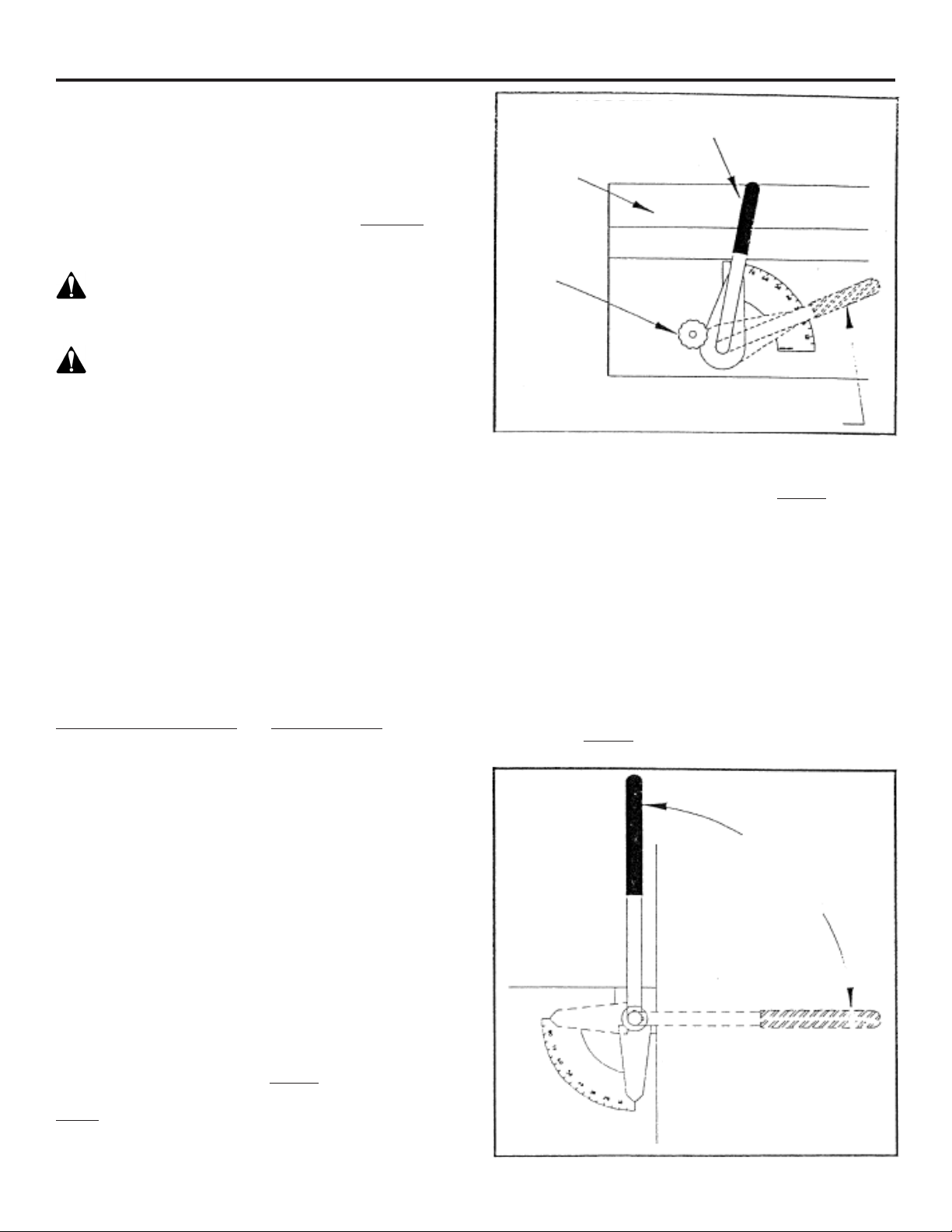
ADJUSTING ROLLS - (See Figure 3) When the roll adjust
handle is straight up, the rolls are at their closest setting,
producing the finest, or smallest, particle size possible
with the current roll corrugation. To increase the roll
spacing and particle size, loosen the locking handle on
the motor side of the mill (See Figure 1) and rotate the roll
adjust handle clockwise. A wider roll spacing is achieved
with the roll adjust handle in the horizontal position. The
curved decal by the indicator pointer of the roll adjust
handle should be used by the operator as a reference
to note frequently used roll spacing for dierent rolling
applications. It is not intended for specific roll spacings.
IMPORTANT: Remember to tighten the locking handle
before resuming any rolling operations.
IMPORTANT: NEVER OPERATE THE MILL WITH THE
ROLLS TOUCHING!
Figure 2
HOPPER GATE CONTROL
MAXIMUM OPENING
HOPPER
HOPPER GATE CLOSED
LOCKING
KNOB
ROLL SPACING
ADJUSTMENT
ROLL SPACING
APPROX. 0.015”
(FACTORY SETTING)
HOPPER
BASIC
ROLL SPACING
APPROX. 1/4”
(MAX. OPENING IS 1/2”
WITH HANDLE
STRAIGHT DOWN)

Page 6 of 26 7/9/19
SETUP / OPERATION
BELT TENSIONING AND ALIGNMENT
To properly tighten the drive belt you should first open the rolls to a gap of approximately 1/4 inch. This is
done by rotating the roll spacing adjustment handle clockwise until it is 90 from vertical.
Tighten the drive belt. The tension should be measured between the motor and flat pulley. The belt should
deflect 3/16” using approximately 60 pounds of force.
Reset the roll gap spacing as instructed on page 6 of the LPE manual.
Periodic checks of all belts should be made to ensure proper alignment, correct tension levels, and detect
worn or deteriorating belts.
To check belt alignment, lay a long straight edge along the cog belt sprockets. The outside edge of all three
should line up, including the motor sprocket.
SHUT DOWN PROCEDURE
During normal operation of this mill, the following shut down procedure should always be followed to ensure
that the rolls are free from excess grain build up that may prevent the mill from starting up properly.
1 When shutting down your mill, always stop the flow of grain into the hopper first.
2 When all grain has passed through the rolls and the hopper is empty, the hopper gate control should be
closed. (rotated clockwise)
3 Finally, disengage the electrical power to the roller mill.
FUSED
SERVICE
DISCONNECT
MOTOR
STARTER
BOX
POWER
DISCONNECT
ON MILL
CONNECT MOTOR
PER MOTOR MFG.
WIRE DIAGRAM
5, 7.5 OR 10 HP MOTOR
METERED POWER SOURCE - 1 PHASE POWER
240 VOLT MAX.
The following are instructional diagram on how to wire the power disconnect box which is located on the roller mill
hopper, just above the electric motor. Below is a diagram covering single phase electricity. The maximum power which a
particular box can handle will be displayed on the box, but should be 60 amps and 220-240 volts, single or 3 phase.
If you have any questions on these instructions or how to wire up the disconnect box, please contact your local
dealership which sold you the mill.

Page 7 of 26 7/9/19
LUBRICATION / SPECIFICATIONS
SPECIFICATIONS
Model LPE 500 LPE 700
Roll Corrugation (Teeth Per Inch)............................ 4, 6 1/2, 8, 10, or 14.................... 4, 6 1/2, 8, 10, or 14
Roll Size .............................................................................. 9” Dia. x 10” Long.......................9” Dia. x 14” Long
Power Requirements
Minimum Horsepower.......................................................... 5.......................................................7.5
Maximum Horsepower....................................................... 7.5 ..................................................... 10
Overall Height (With Legs*).......................................................39” ................................................... 39”
Overall Height (Without Legs*)................................................24” ...................................................24”
Overall Height (Without Legs*) (With Auger Base*)....31 1/2” .............................................31 1/2”
Overall Length............................................................................. 43 1/2”............................................ 43 1/2”
Overall Width...................................................................................28” ................................................... 32”
*Discharge Auger (Diameter).....................................................8”...................................................... 8”
Length................................................................................. 5’ or 10’ ...........................................5’ or 10’
Drive ........................................................................................ Belt.................................................. Belt
*OPTIONS:
Auger Base
Leg Pack
Discharge Auger
LUBRICATION - DANGER: Do not attempt to lubricate, adjust or service the roller mill while it is in operation.
BEARINGS - All pillow block bearings are sealed and as a general rule, REQUIRE NO LUBRICATION. However, the
bearing manufacturer does furnish grease zerks and recommends that the bearings be greased before 1/3 of the
bearing’s calculated life elapses. Usually a pump or two of grease every 100 hours of operation will be sucient.
IMPORTANT: DO NOT OVERGREASE! Overgreasing can cause damage to the bearing seal. Each time the bearings are
greased, be sure to check the condition of the grease lines on the drive side of the mill.
GEARBOX (Discharge Auger Option) - The gearbox is filled at the factory, but the oil level should be checked initially,
and periodically thereafter. It is very important to keep the gearbox from running dry. There will be a slight leakage
around the seals so expect to add grease from time to time. Automatic recommends SAE 80 W-90 multipurpose gear
lubricant.
Page 8 of 26 7/9/19
Figure 4
Figure 5
Figure 6
OPERATION / MAINTENANCE
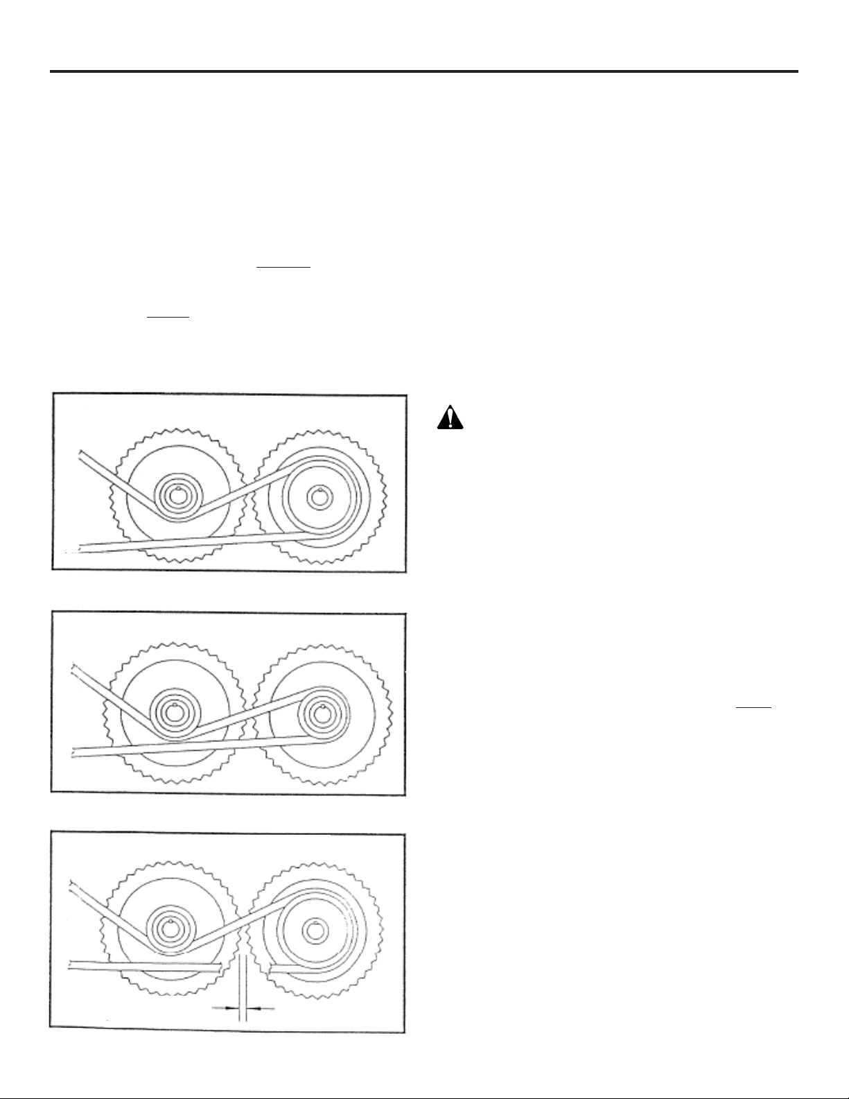
OPTIONAL ROLL CONFIGURATION - This roller mill
is available with five dierent roll configurations and
comes standard with a dierential drive (See Figure 4).
Corrugation numbers refer to the number of corrugations
or “teeth” per inch. The larger the corrugation number,
the smaller the particle size produced. Changing the roll
gap is the next preferred method for adjusting particle
size. (See Adjusting Rolls section, page 6) In addition,
feed consistency, or particle size, may be adjusted by
changing the relative drive roll and idler speeds. This
is accomplished by replacing the drive roll pulley with
a pulley the same size as that of the idler roll. (See
Figure 5). However, when the drive method is changed,
it will generally reduce the capacity of the mill and
not allow as fine a particle size. Consult your dealer, or
Automatic Equipment for recommendations regarding roll
configuration by any other method than those approved
by Automatic Equipment will void the warranty.
MAINTENANCE - Automatic roller mills are manufactured
from the best materials and workmanship available.
Simple adjustments and minimum maintenance have been
emphasized in their engineering. Although all components
of your roller mill are tested and properly adjusted
before it leaves the factory, some may require additional
adjustment after a break in period.
After your roller mill has been in operation for a few hours,
examine the entire machine for loose bolts, set screws,
lock collars, belts, etc. This initial check is an important
first step in an ongoing program for keeping your roller
mill in top running condition and should be performed
periodically as part of the general maintenance of your
roller mill. Like any other implement, your roller mill
requires proper care and intelligence in operation. Misuse
and/or neglect will only cause unnecessary expense and
dissatisfaction.
WARNING: SHIELDS AND GUARDS ARE PROVIDED
FOR YOUR PROTECTION. Although some shields and
guards may need to be removed or opened for servicing
and adjustments, they should always be replaced or
closed before operation resumes.
BELTS - All belts should be inspected for proper
alignment and tension after a few hours of operation.
Tension should be measured between the motor and flat
pulley. The belt should deflect 3/16” using approximately
60 pounds of force. Periodic checks of all belts should be
made to ensure proper alignment, correct tension levels
and to detect worn or deteriorating belts.
PULLEY SET SCREW ADJUSTMENT - The belt drive
system on your roller mill includes several pulleys which
use a setscrew to hold them in place on the key. ONLY
“Cup Point” set screws with knurled tips should be used.
To correctly seat the set screw, turn it “IN” and “OUT”
several times before tightening in place. This will wear a
groove in the key for the setscrew to seat in.
ROLLER TENSION SPRINGS - The roller tension springs
on the idler roll are set at the factory to maintain the
correct amount of pressure. They should be 4 1/2” long
±1/8”. The springs allow the rolls to separate so foreign
objects such as nails, bolts, stones, gravel, etc. may
pass between the rolls. A magnetic grate is standard
on the roller mill and should remove most of the metal
items, but in the event that something gets through, the
spring action will help prevent the roll teeth from being
damaged. If the rolls become out of alignment and require
readjustment, the springs may require similar adjustments.
(See Realigning Rolls, Page 8)
DIFFERENTIAL DRIVE
Idler (left)
SAME SPEED DRIVE
Idler (left)
ROLL SPACING
.015”
Idler (left)

Page 9 of 26 7/9/19
6 Once the roll teeth
touch, turn the
nuts (9) IN about
1/4 to 1/2 flat on
the nut. (See
Figure 7).
NOTE: There are
six flat sides on
each nut. Turning
one full flat means
turning the nut so
that the flats
advance one
position.
7 Hold the nuts (9) in
place and tighten the jam nuts (10) on both sides of
the mill. Recheck that the rolls do not touch by
repeating step 5.
8 Move the roll spacing adjustment handle 5 each way
from center and check to assure the rolls are not
touching. Readjust if necessary. Be sure to tighten jam
nuts (10) when finished.
9 If adjustments were made, measure the length of the
springs (5). They should be 4 1/2” long ±1/8”. If
spring adjustment is needed, loosen the jam nut
(2) on the spring side and move spring nut (3) until
the correct spring length is established. Once
adjusted, tighten the jam nut (2) to hold setting.
10 Make a final check of the rolls for parallel and roll
gap. You may need to use a feeler gauge for 8 cut and
finer rolls. Reinstall the drive belt and shields. Be sure
to remove any tools from the machine before
restarting.
Figure 7
Figure 8
REALIGNING ROLLS
REALIGNING ROLLS - If the rolls ever become out of
alignment (more gap on one end of the roll pair than
the other) they must be realigned to maintain feed
consistency and prolong the life of the rolls. To accomplish
this, follow the instructions below.
DANGER: Before attempting to service your
roller mill be sure to follow the SAFETY SHUTDOWN
PROCEDURE on page 2.
1 Remove the drive belt from all the pulleys and lay it
aside. Loosen the jam nut (item 10) on one of the
sides of the mill. It may be necessary to loosen and
adjust both sides to acquire the correct settings. This
will be determined by how far out of parallel the rolls
are.
2 Adjust the other nut (9) on the same side, until the
rolls are parallel. To check for roll spacing, a strip
of metal banding works well but any strip of metal
approximately 1/32” thick will also work. Slide the
strip between the rolls and verify the roll spacing is
the same along their entire length. Check the spacing
3 or 4 times with the rolls at various rotated positions
to assure the rolls are as close to parallel as possible.
NOTE: Rolls will vary a few thousandths of an inch
in diameter along their length, be sure to check for
the tightest gap.
3 With the rolls parallel you can now set the roll
spacing. Place the roll spacing adjustment handle
straight up with the indicator straight down. This will
place the rolls at their closest possible setting.
4 WARNING: Be careful not to get your hands
between the rolls or between the rolls and the basic
channel.
WARNING: Do not power the mill with the
motor. This creates a personal danger to you and
may cause damage to the rolls if they are touching.
5 By hand, spin the rolls in the same direction
(clockwise) at dierent speeds. Strike the idler roll
shaft at the bearing, towards the drive roll, with a
rubber mallet to ensure that the idler bearing
mount (6) is free to allow the rolls to be at their
closest position. With the rolls spinning freely at
dierent speeds, turn the nuts (9) on both sides of
the mill out evenly until you hear the roll teeth
touch. They will make a ticking sound that should
be easily heard. This is to ensure that the rolls do
not move closer together with the vibration of the
mill. Some additional adjustment may be needed
at this time.
292-1329 5/94
ROLL SPACING
ADJUSTMENT
ORIGINAL
1/2 FLAT
1/4 FLAT
1 FLAT
1
1
1
1
2
2
2
2
3
3
3
3
4
4
4
4
5
5
5
5
6
6
6
6

Page 10 of 26 7/9/19
REPLACEMENT PARTS
DRIVE ASSEMBLY....................................................................................... 11
BASIC ........................................................................................................12-13
HOPPER ASSEMBLY............................................................................14-15
PRIMARY ASSEMBLY ..........................................................................16-17
BELT DRIVE SHIELDS .............................................................................. 18
AUGER BASE (option)............................................................................. 19
DISCHARGE AUGER (option)........................................................ 20-21
REPLACEMENT PARTS
When ordering parts for your roller mill, please state your needs with the following information:
COMPLETE COMPLETE
MODEL NO. SERIAL NO. PART NO. DESCRIPTION
LPE500X8 000000 61-3967 Weldment, Idler Bearing Mount
When you order in this way, you can be certain the correct part will be delivered in the shortest time
possible.
IMPORTANT: Use only genuine factory replacement parts on your roller mill. Do not substitute homemade
or non-typical parts. If a bolt is lost or in need of replacement, for your safety and the preservation of your
roller mill, be sure to use a replacement bolt of the same grade (Usually Grade 5).
Repair parts may be ordered through your nearest Automatic dealer. If there is no dealer in your area, write
or call Automatic Equipment Mfg. Co., Pender, Nebraska 68047, phone (402) 385- 3051.
Page 11 of 26 7/9/19
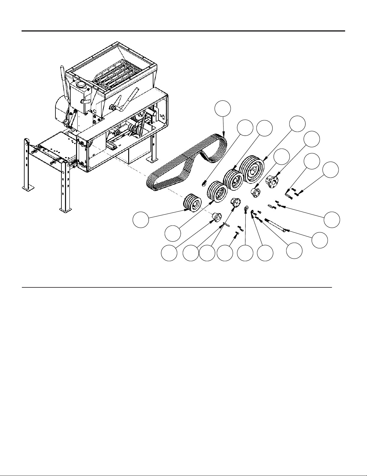
16
711
13
9 3
4
5
3
87
14
LPE500 & 700 DRIVE ASSEMBLY
2
1
12
10
6
14
15
ITEM NO.
PART NUMBER
DESCRIPTION
QTY.
1
100-0224
KEY, 3/8 X 3/8 X 2
2
2
100-0304
KEY, 5/16 X 5/16 X 2 3/4
1
3
201-0120
5/16-18 X 1 BOLT, HH GRD5, ZP
6
4
201-0368
3/8-16 X 1-1/4, BOLT HH GRD5, ZP
3
5
201-0469
5/16-18 X 1 HEX BOLT, GRD 5, ZP
3
6
201-1107
5/8-11 X 9" HH BOLT, ZP
1
7
203-0006
5/8" FLAT WASHER, ZP
2
8
203-0013
WASHER, 5/8 LOCK, ZP
1
9
205-0052
BUSHING, P1-1 3/8
1
10
205-0054
BUSHING, P1-1 3/4
1
11
205-0209
SHEAVE, 4TB86 BROWNING
1
12
205-0221
BUSHING, Q1-1 3/4, BROWNING
1
13
205-0292
SHEAVE, 4TB48, BROWNING
1
14
205-0307
SHEAVE, 4TB62 BROWNING
2
15
205-0414
BUSHING, P1-BB X 5/8'
1
16
251-0083
BELT-V, BB85
4
DRIVE ASSEMBLY
Item No. Part No. Description Qty.
1.................................100-0224 ...........................3/8” x 3/8” x 2” Key ..........................................................2
2.................................100-0304 ...........................5/16” x 5/16” x 2-3/4” Key................................................1
3.................................201-0120 ...........................5/16”-18 x 1” Hex Head Bolt, Grade 5, ZP ......................6
4.................................201-0368 ...........................3/8”-16 x 1-1/4” Hex Head Bolt, Grade 5, ZP ..................3
5.................................201-0469 ...........................5/16” -18 x 1” Hex Head Bolt, Grade 5, ZP .....................3
6.................................201-1107 ...........................5/8”-11 x 9” Hex Head Bolt, ZP........................................1
7.................................203-0006 ...........................5/8” Flat Washer, ZP........................................................2
8.................................203-0013 ...........................5/8” Lock Washer, ZP ......................................................1
9.................................203-0052 ...........................P1 - 1-3/8” Bushing .........................................................1
10...............................203-0054 ...........................P1 - 1-3/4” Bushing .........................................................1
11 ...............................205-0209 ...........................4TB86 Browning Sheave.................................................1
12...............................205-0221 ...........................Q1 - 1-3/4” Browning Bushing .........................................1
13...............................205-0292 ...........................4TB48 Browning Bushing................................................1
14...............................205-0307 ...........................4TB62 Browning Bushing................................................2
15...............................205-0414 ...........................P1-BB x 5/8” Bushing ......................................................1
16...............................251-0083 ...........................BB85 Belt-V.....................................................................4

Page 12 of 26 7/9/19
BASIC
1
3
11
13
7
10
2
4
8 1422
35
40
3
30
16
15
21
20
3233
11
36
39
41
43
38
34
5
6
LPE500 & 700 BASIC ASSEMBLY
18
26
23
24
27
2935
37
42
12
17
9
28
19
31
14
25

Page 13 of 26 7/9/19
BASIC
Item No. Part No. Description Qty.
1...................................... 53-0005 ...................................1-3/4” Pillow Block Bearing ............................................................4
2...................................... 61-1968 ...................................Spring Center .................................................................................2
3...................................... 61-3966 ...................................Take Up Rod, LPE..........................................................................2
4...................................... 61-3967 ...................................Idler Bearing Mount, LPE...............................................................2
5...................................... 61-3968 ...................................Drive Bearing Stop, LPE ................................................................1
6...................................... 61-3969 ...................................Idler Bearing Stop, LPE..................................................................1
7...................................... 61-3984 ...................................LPE500 Basic.................................................................................1
........................................ 61-4009 ...................................LPE700 Basic.................................................................................1
8...................................... 61-4018 ...................................Cam Locking Handle, LPE.............................................................1
9...................................... 61-4025 ...................................LPE500 Cam Adjustment Rod .......................................................1
........................................ 61-4004 ...................................LPE700 Cam Adjustment Rod .......................................................1
10.................................... 71-0450 ...................................LPE500 Roll, 4 Cut.........................................................................2
........................................ 71-0451 ...................................LPE500 Roll, 6.5 Cut......................................................................2
........................................ 71-0452 ...................................LPE500 Roll, 8 Cut.........................................................................2
........................................ 71-0453 ...................................LPE500 Roll, 10 Cut.......................................................................2
........................................ 71-0454 ...................................LPE500 Roll, 12 Cut.......................................................................2
........................................ 71-0455 ...................................LPE500 Roll, 14 Cut.......................................................................2
........................................ 71-0457 ...................................LPE700 Roll, 4 Cut.........................................................................2
........................................ 71-0458 ...................................LPE700 Roll, 6.5 Cut......................................................................2
........................................ 71-0459 ...................................LPE700 Roll, 8 Cut.........................................................................2
........................................ 71-0460 ...................................LPE700 Roll, 10 Cut.......................................................................2
........................................ 71-0461 ...................................LPE700 Roll, 12 Cut.......................................................................2
........................................ 71-0462 ...................................LPE700 Roll, 14 Cut.......................................................................2
11 .................................... 100-1268 .................................Cam Adjustment Rocker, LPE........................................................2
12.................................... 101-4962 .................................10 GA Roll Wear Plate, LPE ..........................................................1
13.................................... 101-4963 .................................14 GA Roll Wear Plate, LPE ..........................................................1
14.................................... 101-4982 .................................LPE500 Cam Side End Plate.........................................................1
........................................ 101-5044 .................................LPE700 Cam Side End Plate.........................................................1
15.................................... 101-4993 .................................Drive Roll Cover, LPE ....................................................................2
16.................................... 101-4994 .................................LPE500 Drive Roll Side End Plate.................................................1
........................................ 101-5049 .................................LPE700 Drive Roll Side End Plate.................................................1
17.................................... 102-4003 .................................Cam Adjustment Pivot, LPE ...........................................................2
18.................................... 102-4006 .................................Flat Bearing Stop, Bolt On, LPE.....................................................2
19.................................... 150-0028 .................................LPE500 Rubber Baes..................................................................2
........................................ 150-0037 .................................LPE700 Rubber Baes..................................................................2
20.................................... 201-0024 .................................1/2”-13 x 1” Carriage Bolt, Grade 5................................................4
21.................................... 201-0034 .................................3/8”-16 x 1” Carriage Bolt, Grade 5, ZP .......................................14
22.................................... 201-0081 .................................3/8”-16 x 3/4” Hex Head Bolt, Grade 2, ZP....................................2
23.................................... 201-0111..................................1/4”-20 x 3/4” Slot Truss Head Screw ............................................6
24.................................... 201-0346 .................................3/4”-10 x 4” Hex Head Bolt, Grade 8, ZP.......................................2
25.................................... 201-0351 .................................5/8”-11 x 2” Hex Head Bolt, Grade 5, ZP .......................................6
26.................................... 201-0368 .................................3/8”-16 x 1-1/4” Hex Head Bolt, Grade 5, ZP.................................2
27.................................... 201-0490 .................................1/2”-13 x 3” Hex Head Bolt, Grade 5, ZP.......................................2
28.................................... 201-0553 .................................1/4”-20 x 1/2” Hex Washed Type F TCS, ZP..................................6
29.................................... 202-0003 .................................3/8”-16 Hex Nut, ZP .......................................................................2
30.................................... 202-0006 .................................5/8”-11 Hex nut.............................................................................14
31.................................... 202-0069 .................................1/4”-20 Hex Flange Whiz Lock Nut, ZP..........................................6
32.................................... 202-0071 .................................3/8”-16 Whiz Flange Lock Nut, ZP...............................................14
33.................................... 202-0072 .................................1/2”-13 Hex Flange Whiz Lock Nut, ZP..........................................4
34.................................... 202-0094 .................................1/2”-13 Hex Nylon Insert Lock Nut, ZP ..........................................1
35.................................... 203-0010 .................................3/8” Lock Washer, ZP.....................................................................4
36.................................... 203-0013 .................................5/8” Lock Washer, ZP.....................................................................6
37.................................... 203-0066 .................................18 GA x 1-1/4” x 3/4” Machine Bushing .........................................8
38.................................... 220-0032 .................................3/16” x 1-1/4” Sping Pin, ZP...........................................................2
39.................................... 222-0078 .................................Comp Spring ..................................................................................2
40.................................... 224-0327 .................................1/4”-28 Grease Zerk.......................................................................2
41.................................... 224-0375 .................................1/8” NPT x 45 Degree Grease Zerk ...............................................2
42.................................... 224-0425 .................................1/4”-28 Self-Tap Straight Zerk ........................................................2
43.................................... 224-0469 .................................1/4”-28 Male to NPT Female Set-Up..............................................2
Page 14 of 26 7/9/19
HOPPER ASSEMBLY
LPE500 & 700 HOPPER ASSEMBLY
5
6
14
2 3
710
8
9
11 13
12
14
15
16

Page 15 of 26 7/9/19
HOPPER ASSEMBLY
Item No. Part No. Description Qty.
1.................................61-3951 .............................LPE500 Slide Gate..........................................................1
...................................61-4000 .............................LPE700 Slide Gate..........................................................1
2.................................61-3952 .............................LPE500 Gate Rod ...........................................................1
...................................61-4001 .............................LPE700 Gate Rod ...........................................................1
3.................................61-3953 .............................LPE500 Gate Holder .......................................................1
...................................61-4013 .............................LPE700 Gate Holder .......................................................1
4.................................61-3954 .............................Gate Handle ....................................................................1
5.................................61-3955 .............................LPE500 Hopper...............................................................1
...................................61-4002 .............................LPE700 Hopper...............................................................1
6.................................61-3956 .............................LPE500 Gate Slope.........................................................1
...................................61-4003 .............................LPE700 Gate Slope.........................................................1
7.................................102-3996 ...........................Bolted Link Arm ...............................................................2
8.................................201-0050 ...........................1/4”-20 x 3/4” Hex Head Bolt, Grade 5, ZP .....................4
9.................................201-0193 ...........................1/4”-20 x 1/2” Hex Head Bolt, Grade 5, ZP .....................4
10...............................201-0443 ...........................3/8”-16 x 1” Hex Head Bolt, Grade 5, ZP ........................4
11 ...............................201-0448 ...........................1/4”-20 x 1-1/2” Hex Head Bolt, Grade 5, ZP ..................1
12...............................202-0090 ...........................3/8”-16 Hex Nylon Insert Lock Nut, ZP............................4
13...............................202-0102 ...........................1/4”-20 Hex Nylon Nut, ZP ..............................................5
14...............................203-0001 ...........................1/4” Flat Washer, ZP........................................................4
15...............................203-0008 ...........................1/4” Lock Washer, ZP ......................................................4
16...............................290-0300 ........................... .75 Round x 5” Vinyl Handle...........................................1

Page 16 of 26 7/9/19
PRIMARY ASSEMBLY
LPE500 & 700 PRIMARY ASSEMBLY
1
2
3
5
6
7
8
9
10
11
1314
15
16
17
18
20
22
23
24
25
26
31
32
28 27
29
30
33
4
12
21
19

Page 17 of 26 7/9/19
PRIMARY ASSEMBLY
Item No. Part No. Description Qty.
1.................................61-3961 .............................LPE500 Magnetic Grate ..................................................1
...................................61-4005 .............................LPE700 Magnetic Grate ..................................................1
2.................................61-3964 .............................LPE500 Frame ................................................................1
...................................61-4010 .............................LPE700 Frame ................................................................1
3.................................61-3970 .............................Cam Handle ....................................................................1
4.................................61-3971 .............................Leg ..................................................................................4
5.................................61-3972 .............................LPE500 Motor Mounting Plate ........................................1
...................................61-4011 .............................LPE700 Motor Mounting Plate ........................................1
6.................................62-3066 .............................LPE500 hopper Assembly ...............................................1
...................................62-3089 .............................LPE700 hopper Assembly ...............................................1
7.................................62-3207 .............................LPE Disconnect Box Assembly .......................................1
8.................................93-0527 .............................LPE500 x 4 Basic Assembly............................................1
...................................93-0528 .............................LPE500 x 6.5 Basic Assembly.........................................1
...................................93-0529 .............................LPE500 x 8 Basic Assembly............................................1
...................................93-0530 .............................LPE500 x 10 Basic Assembly..........................................1
...................................93-0531 .............................LPE500 x 12 Basic Assembly..........................................1
...................................93-0532 .............................LPE500 x 14 Basic Assembly..........................................1
...................................93-0534 .............................LPE700 x 4 Basic Assembly............................................1
...................................93-0535 .............................LPE700 x 6.5 Basic Assembly.........................................1
...................................93-0536 .............................LPE700 x 8 Basic Assembly............................................1
...................................93-0537 .............................LPE700 x 10 Basic Assembly..........................................1
...................................93-0538 .............................LPE700 x 12 Basic Assembly..........................................1
...................................93-0539 .............................LPE700 x 14 Basic Assembly..........................................1
9.................................100-0544 ...........................3/16” x 3/16” x 1” Key ......................................................1
10...............................101-3323 ...........................Idler Support, Third Rod Washer.....................................1
11 ...............................200-1419 ...........................3/4” Hole Plug..................................................................1
12...............................201-0008 ...........................3/8”-16 x 1-1/4” Carriage Bolt, Grade 5...........................8
13...............................201-0024 ...........................1/2”-13 x 1” Carriage Bolt, Grade 5 .................................4
14...............................201-0120 ...........................5/16”-18 x 1” Hex Head Bolt, Grade 5, ZP ......................8
15...............................201-0193 ...........................1/4”-20 x 1/2’ Hex Head Bolt, Grade 5, ZP......................6
16...............................201-0368 ...........................3/8”-16 x 1-1/4” Hex Head Bolt, Grade 5.........................2
17...............................201-0377 ...........................1/2”-13 x 5-1/2” Hex Head, Grade 5, FT..........................2
18...............................201-0527 ...........................1/4”-28 x 5/16” Set Screw................................................2
19...............................201-0537 ...........................5/16”-18 x x1-1/2” Bolt Flsckt Head, FT...........................1
20...............................202-0012 ...........................1/2-13 Square Nut Plate (Not Plated)..............................2
21...............................202-0071 ...........................3/8”-16 Whiz Flange Lock Nut, ZP ..................................8
22...............................202-0072 ...........................1/2”-13 Hex Flange Whiz Lock Nut, ZP...........................4
23...............................202-0090 ...........................3/8”-16 Hex Nylon Insert Lock Nut, ZP............................2
24...............................202-0094 ...........................1/2”-13Hex Nylon Insert Lock Nut, ZP.............................2
25...............................202-0102 ...........................1/4”-20 Hex Nylon Nut, ZP ..............................................2
26...............................203-0001 ...........................1/4” Flat Washer, ZP........................................................6
27...............................203-0002 ...........................5/16” Flat Washer, ZP......................................................7
28...............................203-0003 ...........................3/8” Flat Washer, ZP........................................................4
29...............................203-0005 ...........................1/2” Flat Washer ..............................................................4
30...............................203-0008 ...........................1/4” Lock Washer, ZP ......................................................4
31...............................203-0009 ...........................5/16 Lock Washer............................................................8
32...............................290-0023 ...........................5/16”-18 Plastic Knob ......................................................1
33...............................290-0300 ............................75 Round x 5” Vinyl Handle............................................2
Page 18 of 26 7/9/19
5
1
15 14
7
10 6
3
8
7
4
10
16
17
12
11
LPE500 & 700 BELT DRIVE SHIELDS
9
13 2
ITEM NO.
PART NUMBER
DESCRIPTION
QTY.
1
61-3977
WLDM'T, SHROUD, LPE
1
2
100-0899
CABLE, SHIELD TETHER, LPE
1
3
101-2532
FILLER, BELT SHIELD
1
4
101-4986
SHIELD, MOTOR HOLE, LPE
1
5
101-5011
SHIELD, DRIVE PULLEYS, LPE
1
6
201-0112
1/4-20 X 1/2 SLOT TRUSS HEAD SCREW
2
7
201-0120
5/16-18 X 1 BOLT, HH GRD5, ZP
9
8
202-0069
1/4-20 HEX FLANGE WHIZ LOCK NUT, ZP
2
9
202-0070
5/16-18 HEX FLANGE WHIZ LOCK NUT ZP
2
10
203-0002
WASHER, 5/16 FLAT, ZP
9
11
203-0009
5/16 LOCK WASHER
8
12
224-0468
1/8" FEMALE NPT GREASE ZERK
2
13
225-0049
SWAGING SLEEVE, 3/32 CABLE
1
14
229-0132
LATCH, TENSION
4
15
229-0988
POP RIVET, 3/16 X 1/16-1/8 SB6-2
8
16
253-0184
GREASE LINE, 1/8 X 16
1
17
253-0261
GREASE LINE, 1/8 X 22
1
BELT DRIVE SHIELDS
Item No. Part No. Description Qty.
1.................................61-3977 .............................Shroud.............................................................................1
2.................................100-0899 ...........................Shield Tether Cable .........................................................1
3.................................101-2532 ...........................Belt Shield Filler ..............................................................1
4.................................101-4986 ...........................Motor Hole Shield............................................................1
5.................................101-5011 ...........................Drive Pulleys Shield ........................................................1
6.................................201-0112 ...........................1/4”-20 x 1/2” Slot Truss Head Screw .............................2
7.................................201-0120 ...........................5/16”-18 x 1” Hex Head Bolt, Grade 5, ZP ......................9
8.................................202-0069 ...........................1/4”-20 Hex Flange Whiz Lock Nut, ZP...........................2
9.................................202-0070 ...........................5/16”-18 Hex Flange Whiz Lock Nut, ZP.........................2
10...............................203-0002 ...........................5/16” Flat Washer, ZP......................................................9
11 ...............................203-0009 ...........................5/16” Lock Washer ..........................................................8
12...............................224-0468 ...........................1/8” Female NPT Grease Zerk ........................................2
13...............................225-0049 ...........................3/32” Cable Swaging Sleeve ...........................................1
14...............................229-0132 ...........................Tension Latch ..................................................................4
15...............................229-0988 ...........................3/16” x 1/16”-1/8 SB6-2 Pop Rivet ..................................8
16...............................253-0184 ...........................1/8” x 16” Grease Line.....................................................1
17...............................253-0261 ...........................1/2” x 22” Grease Line.....................................................1

Page 19 of 26 7/9/19
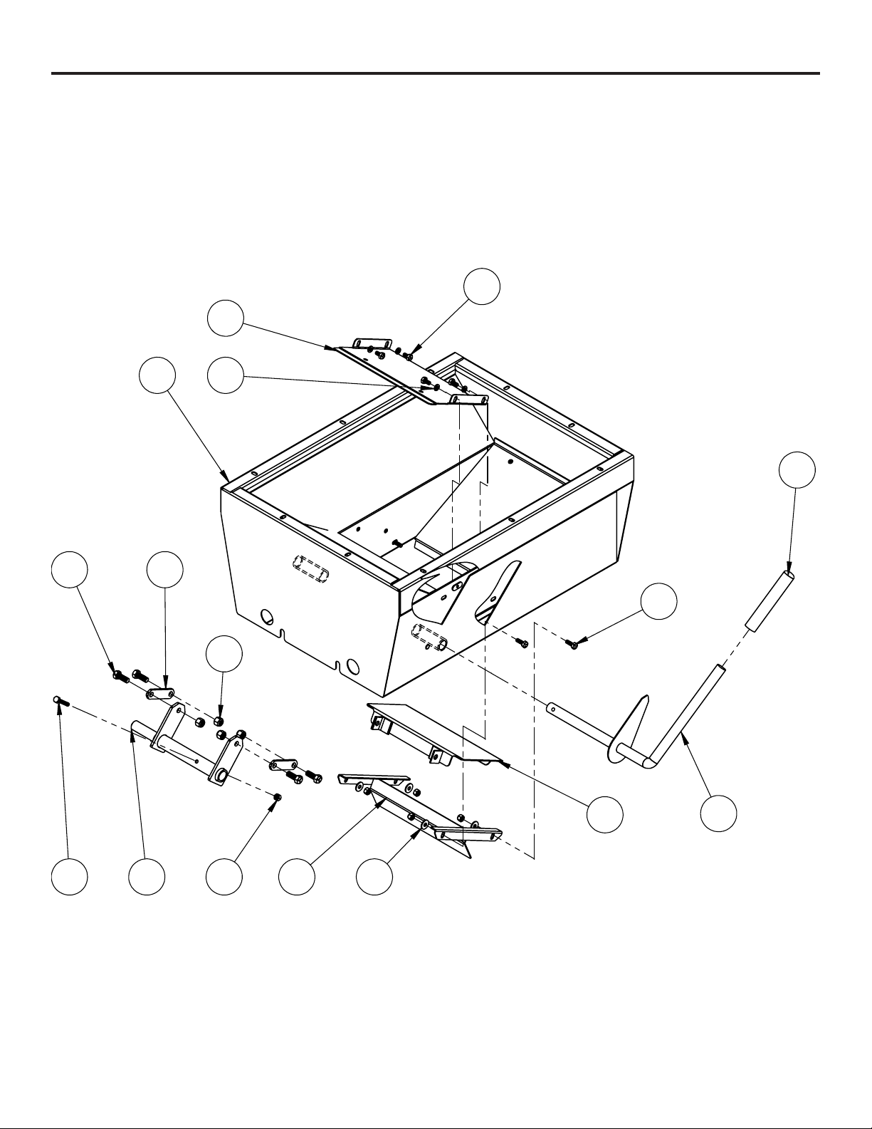
AUGER BASE (Option)
1
2
3
4
5
6
78
9
10
11
12
1315
14
LPE500 & 700 AUGER BASE (OPTIONAL)
11
Item No. Part No. Description Qty.
1.................................61-3975 .............................Auger Base Leg...............................................................2
2.................................61-3976 .............................Auger Base Shield...........................................................1
3.................................62-3067 .............................LPE500 Auger Base Pack ...............................................1
4.................................63-1314 .............................Auger Base B & P Pack...................................................1
5.................................100-0545 ...........................1/4” X 1/4” x 2” Key .........................................................1
6.................................101-2306 ...........................Clean Out Door Cover.....................................................2
7.................................101-5010 ...........................Auger Base Leg Clamp ...................................................2
8.................................201-0007 ...........................3/8”-16 x 1” Hex Head Bolt, Grade 2, ZP ........................8
9.................................201-0120 ...........................5/16”-18 x 1” Hex Head Bolt, Grade 5, ZP ......................6
10...............................201-0351 ...........................5/8”-11 x 2” Hex Head Bolt, Grade 5, ZP.........................1
11 ...............................202-0070 ...........................5/16”-18 Hex Flange Whiz Lock Nut, ZP.......................10
12...............................202-0073 ...........................5/8”-11 Whiz Flange Lock Nut, ZP...................................1
13...............................203-0003 ...........................3/8” Flat Washer, ZP........................................................8
14...............................203-0006 ...........................5/8” Flat Washer, ZP........................................................4
15...............................203-0010 ...........................3/8” Lock Washer, ZP ......................................................8

Page 20 of 26 7/9/19
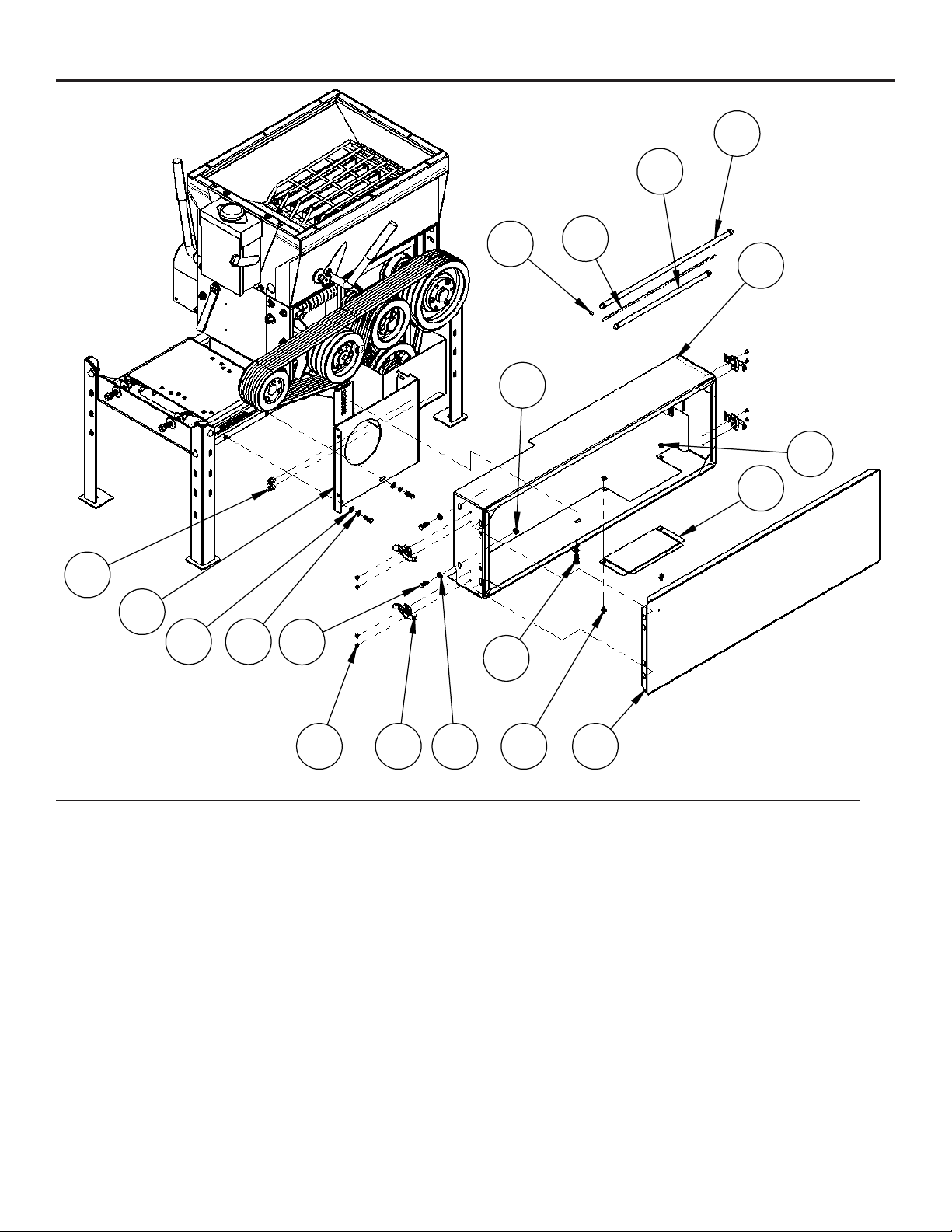
DISCHARGE AUGER (Option)
LPE500 & 700 DISCHARGE AUGER (OPTIONAL)
1
2
3
4
5
7
8
9
10
11
13
14 15 12
16
17
18
19
20
21
22
25
26
23 24
6
This manual suits for next models
1
Table of contents
Other Automatic Industrial Equipment manuals


