Automatic LPM200 User manual

405-0525 Rev A Page 1 of 16 4/5/16
LPM200
Stationary Roller Mill
Operator, Parts &
Installation Manual

405-0525 Rev A Page 2 of 16 4/5/16
Introduction
Congratulations! You are now the owner/operator of America’s nest roller mill. Please take a few
minutes to be sure that you understand the maintenance and operation of this roller mill. Read this
operator’s manual carefully: you’ll get better results and have fewer problems.
After your roller mill has been in operation for a few hours, check for loose bolts, setscrews, belts,
etc. All are tight when the roller mill leaves the factory; however, after a break-in period, some items
may require additional tightening. Like any other machine, your Automatic roller mill requires proper
care and intelligence in operation. Misuse and neglect will only cause unnecessary expense and
dissatisfaction.
This manual is written as a guide for owners and operators of the Automatic LPM200 model roller mill.
Read it carefully and follow the suggestions made. Keep this manual in a convenient place for quick,
easy reference, and use it whenever questions arise.
Fill in the following information now for future reference and convenience. Always give this information
to your dealer when ordering new parts. If at any time it becomes necessary for you to write directly
to Automatic Equipment Manufacturing Company for additional information, give the model and serial
number of your machine, and as much descriptive information as possible. It will enable us to more
thoroughly and quickly expedite your order.
Model No. ______________________________ Serial No._______________________________
Date of Purchase ________________________
Name and Address of Dealer ______________________________________________________________
______________________________________________________________
Dealer/Operator Pre-Use Inspection Checklist
Although everything is in working order when the roller mill leaves the factory, some components may
get out of adjustment in transit. The following inspection must be made prior to operation. Check each
item listed and make adjustments if necessary. Refer to the corresponding sections of the manual to
determine the correct settings for individual items.
•Check all belts for proper tension and alignment.
• Check to make sure the set screws in all pulleys and bearings are tight.
• Check all grease line connections and lines for damage during shipment.
• Make a general check for bolts that may have vibrated loose during shipment.
• Check greased bearings for proper lubrication.
• Check to make sure all shields and guards are in place.
• After operating the roller mill for the rst few times, go through this checklist again. Some bolts,
setscrews and belts may require additional adjustment during this break-in period.

405-0525 Rev A Page 3 of 16 4/5/16
DO NOT OPERATE OR USE THIS EQUIPMENT UNTIL THE FOLLOWING
OPERATING AND SAFETY INSTRUCTIONS HAVE BEEN READ AND
UNDERSTOOD. FAILURE TO UNDERSTAND AND PRACTICE GOOD SAFETY
PROCEDURES COULD RESULT IN PERSONAL INJURY OR DEATH.
All farm machinery is inherently dangerous to children and to persons unfamiliar with its general
operation. Children should not be permitted in areas where machinery of this nature is operating.
Since mills contain numerous moving parts, some of which may not always be visible to the operator,
they can be extremely dangerous. Steps should be taken to assure the safety of the operator, and
any other people in the area. Automatic Equipment strongly recommends that no person be permitted
to operate this mill without a thorough understanding of how the machine works and the precautions
to be observed.
The operator of this machine should be a responsible adult who is familiar with farm machinery,
and trained in its operation. REMEMBER! Your best insurance against accidents is a careful and
responsible operator. A careless operator is a liability to himself and those who work with him.
Because of the dry, highly ammable material associated with this machine, FIRE FIGHTING
EQUIPMENT SHOULD BE READILY AVAILABLE DURING THE OPERATION OF THIS MACHINE.
Before operating this equipment, be sure to read and understand this operator’s manual. If there is any
portion of the manual, or any phase of the roller mill’s operation you do not understand, be sure to contact
your local Automatic dealer or Automatic Equipment, Pender, Nebraska. 402-385-3051.
SAFETY PRECAUTIONS - BEFORE OPERATION
1. Keep the mill in good repair. Good maintenance is your responsibility. A poorly maintained
machine is an invitation for trouble. Always use proper tools when servicing your mill.
2. DO NOT start, operate, or attempt repair work on the mill until you carefully read and
thoroughly understand this operator’s manual.
3. Be sure all shields are in place and all bolts are tight throughout the mill.
4. Be sure the rolls and drive belts are properly adjusted and in good condition. (See Operation
Section)
5 Be sure there are no tools or other foreign objects lying on or in the machine.
continued to page 4
Safety
405-0525 Rev A Page 4 of 16 4/5/16
SAFETY PRECAUTIONS - DURING OPERATION
1. DO NOT wear loose-tting clothing that may catch in moving parts.
2. Children should not be permitted in areas where machinery of this nature is operating.
3. DO NOT operate this machine until you are sure everyone is clear of the area.
4. NEVER leave the mill running unattended.
5. Always keep hands, feet, and clothing away from moving parts.
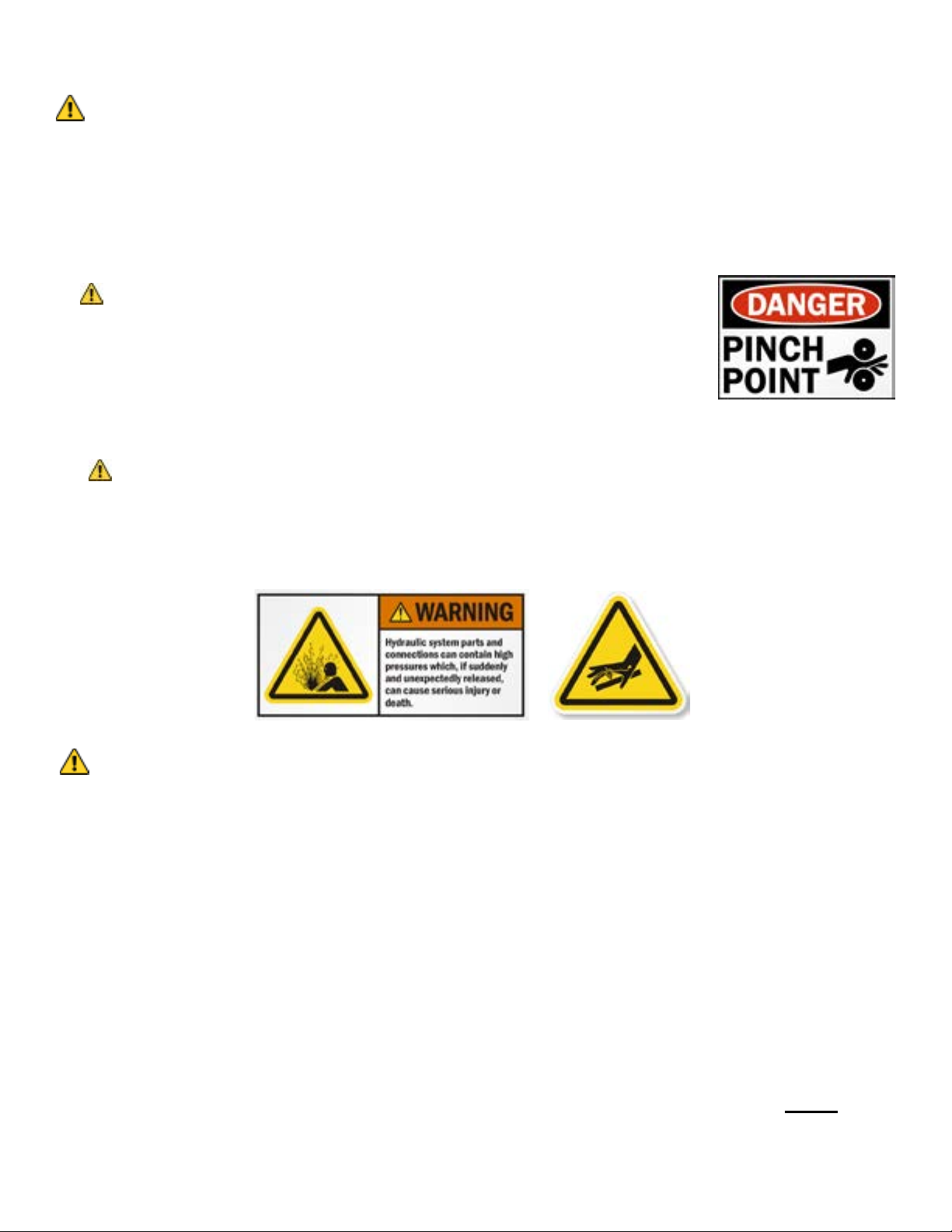
6. DANGER Keep hands and feet out of the hopper when machine is in
operation. Never remove safety grates, or use your hands or feet to dislodge
any obstruction from the mill. Never try to push or force feed grain or snow
that may be bridged or laying in the hopper.
7. NEVER sit or stand on the mill while it is in operation.
8. NEVER adjust or service the unit while it is in operation.
9. NEVER open shields, mill access doors or clean out doors while the mill is in operation.
10. DANGER Avoid contact between the discharge conveyor and overhead electrical lines. Failure
to heed warnings will result in serious personal injury or death.
11. Hydraulic uid can cause serious burns. Hydraulic uid escaping under pressure can have
enough force to penetrate the skin and may also infect a minor cut or opening in the skin. If
injured by escaping uid, see a doctor at once. Make sure all connections are tight and that hoses
are in good condition.
Safety
SAFETY PRECAUTIONS - SERVICE AND REPAIR
1. SAFETY SHUTDOWN PROCEDURE: Working on the mill when it is operating is expressly
prohibited. Never clean, adjust, lubricate, or otherwise service this machine until the following
steps have been taken.
A. Disengage the power source.
B. Lock all switches.
C. Wait until all mechanical motion has stopped on the mill.
Only when these precautions have been taken, should you proceed in the adjustment or servicing
of the mill. Failure to follow the above procedure could lead to death or serious personal injury.
2. Keep the mill in good repair. Good maintenance is your responsibility. A poorly maintained
machine is an invitation for trouble. Always use proper tools when servicing machine, making
certain that they are removed from the unit when services or repairs have been completed.
3. All mills are equipped with shielding to protect the operator from injury. For purposes of clarity
only, some illustrations in this manual may show the mill with the shields removed or missing.
Although shields may be opened or removed for servicing and repair of the mill, they MUST
always be closed or replaced before operation resumes.

405-0525 Rev A Page 5 of 16 4/5/16
continued to page 6
ROLLER MILL MAINTENANCE AND OPERATION
Automatic Grain roller mills are manufactured from the best materials and workmanship available -
each has been tested and properly adjusted at the factory before shipping. Simple adjustments and
minimum maintenance have been emphasized. Reasonable care and operation will assure many
years of trouble-free service.
• BE SURE roller mill is mounted on a rm base. The machine should be level while operating so
the grain will ow evenly across the rolls. This will eliminate unnecessary strain on roll bearings
and shafts, and also do a better job of rolling.
• ELECTRIC POWERED UNITS should be operated at about 600 RPM. Use a pulley ratio of 3 to 1
on 1800 RPM motors.
• IT IS IMPORTANT that all units be checked after the rst few hours of service to insure that all
set screws, lock collars, and other hardware has remained secure. This operation should be
performed periodically as part of general maintenance on your roller mill.
• ROLLER TENSION SPRINGS on oating roll are set at the factory to maintain just the right
amount of pressure. NEVER readjust compression spring tension. These springs prevent
stoppage, allowing foreign objects such as nails, bolts, etc. to pass between rolls. On all of our
mills, magnets are available and recommended, as they separate pieces of iron and steel from the
feed. Saving the life of just one animal will pay for several magnet installations.
• HOPPER GATE CONTROL. Your roller mill will not start with grain between rolls. Always start
roller and bring rolls to full RPM before opening feed gate. Make sure feed gate in hopper is
closed before putting grain in hopper. If grain is released to rolls before they are turning, grain will
pile up and it will be necessary to clean out between rolls and run remaining kernels through by
hand before starting.
• ADJUSTING FEED ROLLS from ne to medium or coarse grind, a turn of the handle on the quick-
adjust in the rear of the mill will set your rolls. To move roll inward, remove lock pin, turn quick-
adjust handle counter-clockwise. To move roll outward, remove lock pin turn quick-adjust handle
clockwise. This will assure you of an even and proper setting, adjusting both sides of the roll at
the same time. After the adjustment has been made always lock setting by placing lock pin on the
right side of chain link welded to the end plate
• DON’T OVERCROWD THE ROLLS - keep a ribbon of grain going between the rolls, and you’ll do
a better job of rolling. This is especially true of oats and barley. It is not necessary to completely
atten the kernel. The grain becomes easy to digest when the hard coat or hull is broken open,
exposing the nutrients to the digestive juices.
• BEARINGS - All pillow block and cast ange bearings are sealed and as a general rule, require no
lubrication. However, the bearing manufacturer does furnish grease zerks and recommends the
bearings be re-greased before one-third (1/3) of the bearings’ calculated life elapses. Usually just
a pump or two of grease per bearing before start up each harvest or after the unit has not been
used for a month or more will be sufcient.
IMPORTANT - DO NOT OVER GREASE. Over greasing can cause damage to the bearing seal.
• ROLLER CHAIN - All mill roller chains should be lubricated every 4 hours of normal use. Use a
chain lubricant or the following weight oil:
• REALIGNING ROLLS... If rolls should ever come out-of-alignment, (more gap on one side of
the roll pair than the other side), they must be realigned to maintain feed consistency. This can
be accomplished by rst removing the connecting link, from the quick adjust chain, and then
removing the chain from the sprockets. The rolls can now be brought back into alignment by
turning the quick adjust handle. Check the gap between the rolls with a feeler gage and turn the
quick adjust handle until the gap is equal at both ends of the roll pair.
Replace the chain and connecting link previously removed, to complete the procedure
-20F to 0F SAE 5
0F to 20F SAE10
20F to 40F SAE20
40F to 100F SAE30
405-0525 Rev A Page 6 of 16 4/5/16
Your roller mill is designed to eliminate complicated adjustments. There are only two (2) major points
of adjustment for any small grain or shelled corn - roller spacing and hopper control gate.
1. HOPPER GATE. Open feed gate gradually until you reach the maximum ow of grain that power
will handle. If it becomes necessary to stop the machine at any time before hopper is empty, be
sure to close the feed door before shutting off power.
2. ROLLER SPACING. This depends upon the type of grain to be rolled. Different grain varies in
size, shape, toughness and moisture content. This is also true of the same kind of grain from
different localities. For this reason, it is impossible for us to tell you how to set the rolls. Do not
over-roll hard or dry grains, as this will cause dusting. Remember, proper adjustment keeps dust
at a minimum, even when rolling the driest grain.
The closest roll setting is preset at the factory and as a rule and should not require additional
adjustment. However, for certain types or conditions of rolling, some “ne tuning” may be required.
IMPORTANT - Check to make sure the roll teeth do not come in contact with each other by turning
the mill by hand after each adjustment.
When ordering parts for your mill, please state your needs with the following information:
MODEL NO. SERIAL NO. PART NO. DESCRIPTION
LPM-200 x 4 000000 101-2467 Shim, 20 Ga
When you order in this way, you can be certain the correct part will be delivered in the shortest time possible.
IMPORTANT: Use only genuine factory replacement parts on your mill. Do not substitute homemade or non-
typical parts. If a bolt is lost or in need of replacement, for your safety and the preservation of your mill, be sure
to use a replacement bolt of the same grade (Usually Grade 5).
Repair parts can be ordered through your nearest dealer. If there is no dealer in your area, call
Automatic Equipment Manufacturing at (402) 385-3051.
Replacement Parts
Basic Assembly ..........................................................................................7/8
Chain Drive ................................................................................................. 9
Belt Drive ................................................................................................... 10
Auger Base .............................................................................................. 11/12
Hopper Assembly ....................................................................................... 13
Frame ......................................................................................................... 14
Parts Index
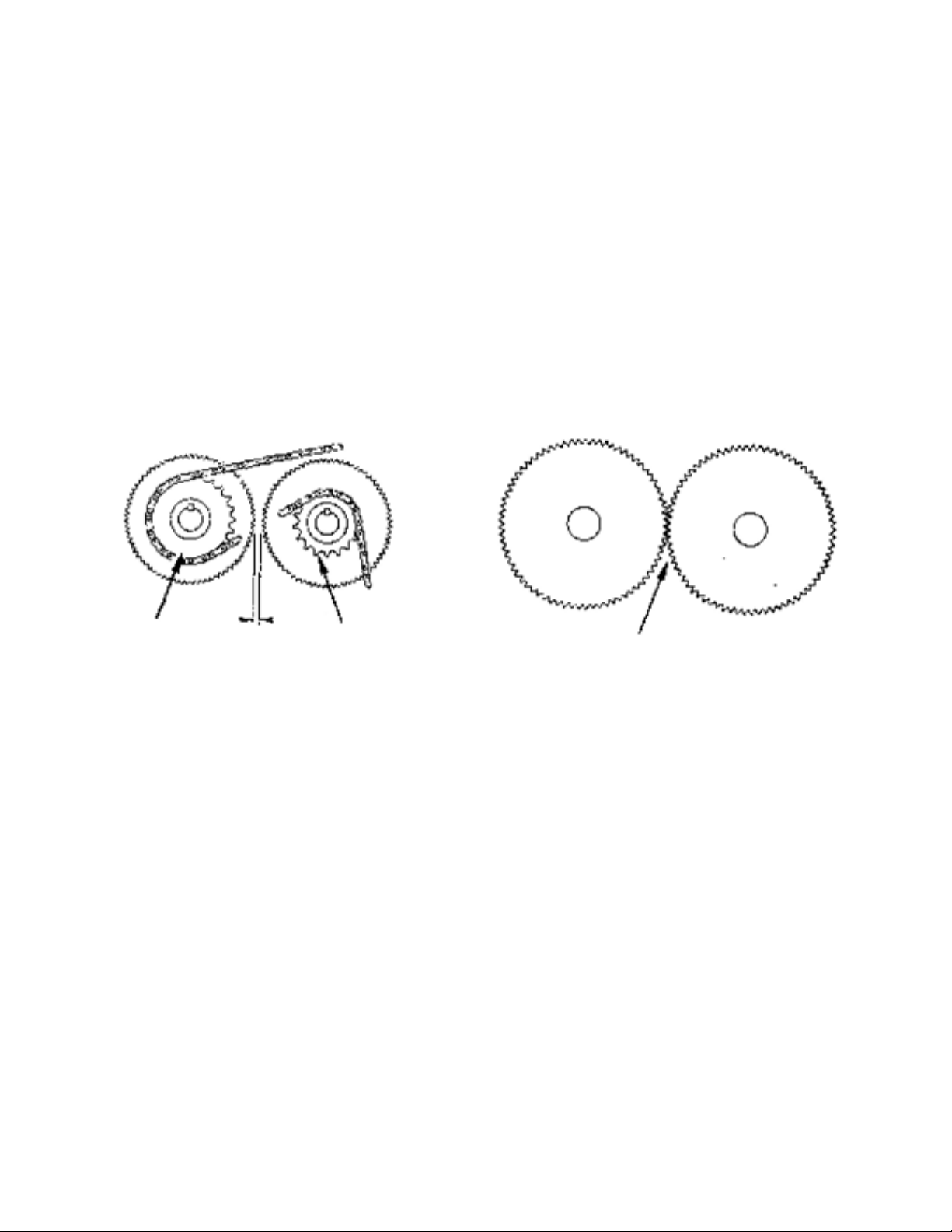
DETAILS OF SPROCKET AND CHAIN routing on mills
equipped with fast roll chain drive. Never operate mill
with rolls touching each other.
DETAILS OF ROLLERS on mills when no chain
drive is used. As such, rolls can be meshed.
Drive roll --
larger sprocket
Idler roll --
smaller sprocket Rolls set together (meshed position)
Note: Rolls turn at same speed.
1/32”

405-0525 Rev A Page 7 of 16 4/5/16
Basic Assembly
continued to page 8

405-0525 Rev A Page 8 of 16 4/5/16
Basic Assembly cont’d
Ref.
No. Part No. Description
1 100-0096 ................................... Front End Plate 200
2 62-0934 ............................... 1 3/8 Pillow Blk Brg 200
209-0001 .............................1 3/8 Bearing Insert 200
3 61-0981 ....................................... Right Channel 200
61-0982 ..........................................Left Channel 200
4 102-0045 ........................Take Up Bearing Block 200
5 62-0931 ...........................1 3/8 Take Up Bearing 200
6 202-0037 ............................ 3/4-10 Hex Jam Nut 200
7 .................................................. NOT USED ON 200
8 202-0074 .................................3/4-10 Whiz Lock Nut
9 104-0170 ................................. 5/16 Dia. Spacer 200
10 100-0352 .............................................. Adj. Rod 200
11 222-0001 ...................................Compression Spring
12 220-0006 .....................................1/4 x 1 1/2 Roll Pin
13 104-0001 ........................................Q.A. Wrench 200
14 61-0455 ..................................... Q.A. Drive Sprocket
15 200-0947 .............................1/8 x 2 13/16 Safety Pin
16 200-0396 ................................................ #27 S Hook
17 100-0391 ........................#4 Twin Loop Chn 10 Links
Ref.
No. Part No. Description
18 206-0083 ................................ #41 x 64 P. Chain 200
(Incl. Conn. Lnk.)
19 210-0004 ............................................ Q.A. Eccentric
20 202-0063 ...................................... 3/4-10 Slotted Nut
21 61-0456 .......................................Q.A. Idler Sprocket
22 206-0095 ...........................................#41 Conn. Link
23 209-0003 ............................................Thrust Bearing
24 61-1461 ......................................Rear End Plate 200
25 71-0119 ...................................... 4 Cut Idler Roll 200
71-0120 ................................ 6 1/2 Cut Idler Roll 200
71-0121 ...................................... 8 Cut Idler Roll 200
71-0122 .................................... 10 Cut Idler Roll 200
26 71-0091 .....................................4 Cut Drive Roll 200
71-0092 ...............................6 1/2 Cut Drive Roll 200
71-0093 .....................................8 Cut Drive Roll 200
71-0094 ...................................10 Cut Drive Roll 200
405-0525 Rev A Page 9 of 16 4/5/16
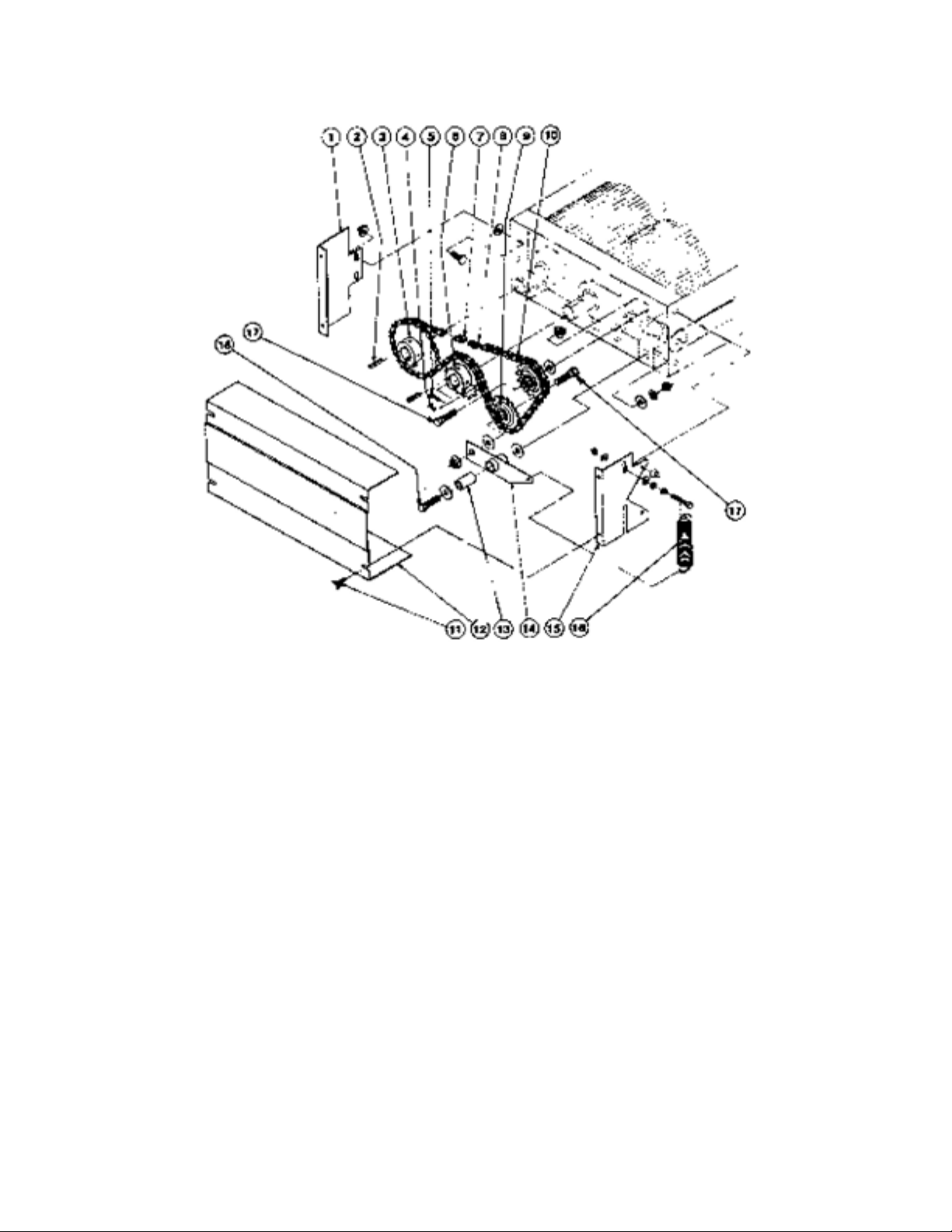
Chain Drive
Ref.
No. Part No. Description
1 61-1675 .............................................................................................. Support w/ Wld Nut Chn Shld
2 100-0058 ...........................................................................................................5/16 x 1 1/2 Sq. Key
3 204-0009 ................................................................................................... 5026 x 1 3/8 w/ Grip Hub
4 201-0271 ................................................................................ 5/16 - 18 x 3/8 Socket HD Set Screw
5 201-0269 ............................................................................ 5/16 - 24 x 1 1/4 Socket HD Cap Screw
6 204-0006 .........................................................................................5018 x 1 3/8 w/ Grip Hub (Fast)
204-0009 ...................................................................................... 5026 x 1 3/8 w/ Grip Hub (Same)
7 206-0052 ...................................................................................................................#50 Conn. Link
8 206-0042 .......................................................................................................................... #50 Offset
9 204-0050 ............................................................................................ Idler Sprocket #50 x 17 Tooth
10 206-0017 .......................................................................... #50 x 76 P. Chain (Incl. Conn. Lnk.) Fast
206-0096 ...............................................................................................................#50 x 79 P. Chain
(Incl. Conn. Lnk. & Offset) Same
11 201-0272 .............................................................................................5/16 - 18 x 3/4 Thumb Screw
12 101-2521 ..............................................................................................................Shield, Chain, 200
13 107-0612 ..................................................................................................... Pivot Tube Support 200
14 61-1674 ........................................................................................................................Idler Brkt 200
15 61-1676 ............................................................................................ Support w/ Wld Nuts Chn Shld
16 222-0003 ......................................................................................... Extension Spring 1.3125 x 5.53
17 201-0026 ..................................................................................................................5/8 - 11 x 2” HH
18 201-0125 ............................................................................................................. 5/8 - 11 x 3 1/2 HH

405-0525 Rev A Page 10 of 16 4/5/16
Belt Drive
Ref.
No. Part No. Description
1 61-1679 ........................................................................................................... Brkt., Belt Shield 200
2 205-0008 ...................................................................................................... 2BK120H Sheave, 200
3 205-0047 ......................................................................................................... H 1 3/8 Bushing, 200
4 101-2532 .......................................................................................................Filler Plate, Belt Shield
5 102-1295 ............................................................................................................Strip Motor Support
6 201-0272 ......................................................................................................5/16 - 18 Thumb Screw
7 61-1608 ............................................................................................................Back Belt Shield 200
8 251-0030 ..................................................................................................................... B-54 Belt 200
9 205-0007 .................................................................................................. 2BK40H Sheave 200-400
10 205-0045 ...................................................................................H-1 1/8 Bushing for 1 1/8 Mtr. Shaft
11 61-1681 .....................................................................................................................Belt Shield 200

405-0525 Rev A Page 11 of 16 4/5/16
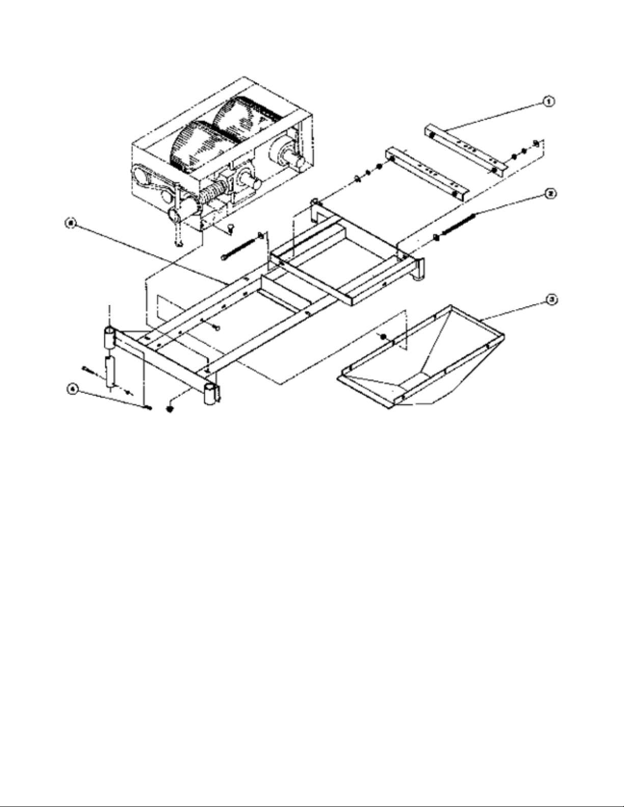
Auger Base (Optional)
continued to page 12

405-0525 Rev A Page 12 of 16 4/5/16
Auger Base (Optional) cont’d
Ref.
No. Part No. Description
1 101-2507 ...........................................................................................Seal Ch. Side Aug. Base #200
2 61-1683 .............................................................................................................Aug. Out Base #200
3 201-0278 .......................................................................................3/8 - 16 x 3/4 Cup PT. Set Screw
4 225-0015 .............................................................................................. 6” Ring Clamp Set, 200-400
5 61-1602 ...................................................................................................................Leg, Feed Meter
6 100-0464 ..................................................................................................... 5/16 x 5/16 x 1 Key 200
7 204-0042 ...................................................................................... 5014 x 1 3/8 TYP. B. SPRKT 200
8 206-0042 .......................................................................................................................... #50 Offset
9 204-0050 ..................................................................................................................5017 Idler Sprkt
10 206-0052 ...................................................................................................................#50 Conn. Link
11 100-0292 .......................................................................................................... 1/4 x 1/4 x 1 1/4 Key
12 206-0019 .................................................................................................................50 x 49 P. Chain
(Incl. Conn. Lnk. & Offset) 200
13 204-0002 ........................................................................................................5020 x 1 Type B Sprkt
14 221-0001 ...................................................................................................................... 1 Lock Collar
15 211-0023 ............................................................................................................1 Flangette Housing
16 209-0032 ..................................................................................................... BRG. Insert 1 Flangette
17 202-0017 ............................................................................................................. 5/16 - 18 Wing Nut
18 101-2414 ..................................................................................................... Chain Shield Aug. Base
19 101-2508 ................................................................................................Cover, Clean Out Door 200
20 101-2543 ............................................................................................................. Cover, F. KC. Boot
21 61-2139 ........................................................................................................200 Screw, Auger Base

405-0525 Rev A Page 13 of 16 4/5/16
Hopper
Ref.
No. Part No. Description
4 61-1684 ............................................................................................................. Magnetic Grate 200
5* 101-3426 ..............................................................................................................Corner Bolt-In 200
6 202-0018 ............................................................................................................... 3/8 - 16 Wing Nut
7 102-1231 ............................................................................................................. Stop, Hopper Gate
8 101-2450 .................................................................................................................. Brkt. Door Lock
9 61-1682 .............................................................................................................. Hopper Wldm’t 200
10 61-1672 .................................................................................................... Gate Wldm’t, 200 Hopper
* Available for hoppers made prior to 1986.
405-0525 Rev A Page 14 of 16 4/5/16
Frame
Ref.
No. Part No. Description
1 61-1671 ...............................................................................................................Motor Mount, #200
2 61-1623 ................................................................................................................... ADJ. Rod Motor
3 61-1695 (optional) .................................................................................................. Downspout #200
4 201-0278 .........................................................................3/8 - 16 x 3/4 SQ. HD KN. C.P. Set Screw
6 61-1677 .................................................................................................................Frame Skid, #200

405-0525 Rev A Page 15 of 16 4/5/16
Troubleshooting
This section is a condensed chart to help you remedy problems if unsatisfactory operation
occurs. If you are unable to determine and correct the trouble, consult your authorized dealer.
TROUBLE CAUSE REMEDY
Excessive Roll Wear 1. Overfeeding with excess
grain continually sliding
off top of rolls creates
friction and excessive roll
wear.
Keep rolls “hungry”. Adjust control gate to feed in only amount of grain rolls
will take away. Usually overfeeding is not the cause for roll wear on deep-
grooved rollers.
2. Crushing abrasive
materials other than
grain.
Mills are designed to be used only on grain or similar textured materials.
3. Foreign matter, such as
metal, going between
rolls.
We recommend a magnetic trap to remove steel or iron from the grain.
4. Gravel in grain. Sand and small gravel is difcult to remove from grain because of similar
sizes as grain. Larger gravel and small rocks can be removed by screening
with wire hardware cloth on frame mounted in hopper.
Excess Vibration 1. Uneven ow of grain into
mill.
Eliminate “surging of grain” into mill as much as possible.
2. Excess RPM Recommend operation 900 to 1,000 RPM.
Whole Grain Coming
Through Mill
1. Improper setting of rolls. Rolls should be set closer together to crimp all grain being processed.
2. Over feeding. Grain control gate opened so wide rolls will not take all grain and builds
up above rolls. This can cause some whole grain to go over top and not
between rolls.
3. Uneven size kernels. This could be reason for a few small, poorly developed whole kernels going
through mill. It is better to not set mill to crack these if in doing so you would
“over-roll” the majority of the kernels.
Abnormal Power
Requirement
1. Overload on mills. Running damp, high moisture grain can cause “sticking to the rolls,” and
cause an abnormal power requirement on new mills. There sometimes can
be some sticking of dry grain to new rolls, particularly on oats and barley.
This condition should not continue after 200-300 bushels of grain has been
run.
2. Opening grain control
gate too fast and too far
open.
Always open gate slowly and open only as far as necessary to keep rolls
“hungry”. Don’t overfeed rolls and cause an excess building up of grain in roll
pocket between rolls.
Mill is Hard to Start 1. Grain between rolls. When grain is between rolls, separate rolls to allow grain to fall through
or turn rolls backwards and scoop out grain by hand. The best remedy is
to make a practice of closing gate before stopping mill so no grain is left
between rolls.
2. Low Voltage On electric motor driven units, check line loss for low voltage.
Grain too Fine or
Dusting of Grain
1. Over rolling. Open control gate to allow more grain to feed into rollers or readjust spacing
of rolls.
2. Rolling mixed grain. If mixed grains of different sizes are run together, to crack or crimp the small
grain, the rolls “over roll” or pulverize larger kernels in mixed grain. As a
general rule, all grains should be rolled separately and then mixed after
rolling.
3. Failure to reset rolls for
different varieties of grain
Always reset rolls every time a different grain is to be processed.
4. Very dry grain,
particularly when hard.
Open rolls wider than normal to eliminate over-rolling. On extreme cases,
grain can be tempered by sprinkling a small amount of water over grain to be
rolled and let stand 8 to 12 hours. This is generally done in small holding bin
or wagon. The amount of moisture used depends on dryness of grain.
Loose Sprockets 1. Set screws loose. Check set screw rst time mill is operated.
2. Loose chain Keep chain in snug running condition by shifting idler.

405-0525 Rev A Page 16 of 16 4/5/16
It is a continuing policy of Automatic Equipment Manufacturing Company to make improvements. The
company reserves the right to make these improvements without incurring any obligation to add them
to machines already in the eld. Many years of research combined with experience gained through
close contact with operators have been drawn upon in designing your mill.
Please visit us at www.automaticag.com for our complete line of
agricultural equipment.
TO BE VALID, THE WARRANTY CARD MUST BE COMPLETED IN ITS ENTIRETY BY
AN AUTHORIZED DISTRIBUTOR OR DEALER AND SENT TO AUTOMATIC EQUIPMENT
MANUFACTURING COMPANY, P.O. BOX 430, PENDER, NEBRASKA 68047. FAILURE TO DO SO
WILL VOID THIS WARRANTY.
The manufacturer warrants all AUTOMATIC roller mills to be free from defects in material and
workmanship under the normal use and service for which the machine was intended.
ONE YEAR WARRANTY - At any time within one (1) year from date of delivery to the original
purchaser, the manufacturer will furnish replacement parts or repair material for any portion of the
roller mill found to be defective. Such replacement part or repair material shall be furnished without
cost to the owner or the user through an authorized dealer, or F.O.B. factory at manufacturer’s
option. Automatic liability under this warranty must be for part or parts but not for such labor charges
involved for removing and replacing defective parts. The warranty repair period for equipment used
for commercial or rental purposes is limited to thirty days. All rolls are guaranteed for life against
breakage.
This warranty does not apply to any part of an Automatic roller mill which has been subject to misuse,
neglect, alteration, accident, or damage caused by re, ood, or other damage beyond control of the
manufacturer. IN NO EVENT SHALL THE OWNER BE ENTITLED TO RECOVER FOR INCIDENTAL
OR CONSEQUENTIAL DAMAGES SUCH AS, BUT NOT LIMITED TO, LOSS OF CROPS, LOSS
OF PROFITS OR REVENUE, OTHER COMMERCIAL LOSSES, INCONVENIENCE OR COST
OF RENTAL OR REPLACEMENT EQUIPMENT. No responsibility is assumed for delays or failure
caused by strikes, Government regulations, or other circumstances beyond the control of the
manufacturer or authorized dealer or distributor. Further, tires and tubes are warranted directly by the
respective manufacturer only and not by Automatic Equipment Manufacturing Company.
Automatic Equipment Manufacturing Company assumes no liability for damages that might be
inicted on the operator, spectator or general public who might be in the general area while the
machine is in operation, or for any cause whatsoever.
Removal of original serial number voids this warranty in its entirety..
Warranty
Table of contents
Other Automatic Industrial Equipment manuals


