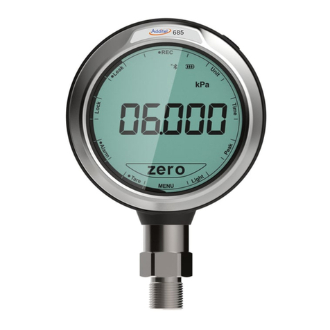
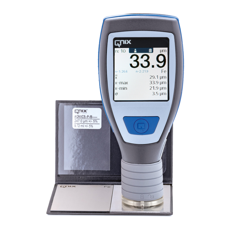
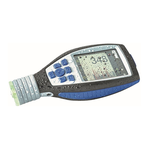
Automation Dr. Nix QNix 8500 User manual


Instruction Manual QNix®8500
- 2 -

Instruction Manual QNix®8500
- 3 -

Instruction Manual QNix®8500
- 4 -
Content
1General............................................................................................................................... 6
2Storage and Transportation............................................................................................. 6
3Changing the Probes........................................................................................................ 6
4Power Supply and Changing the Batteries .................................................................... 6
5Operating the Gauge......................................................................................................... 7
5.1 Stationary Application ......................................................................................................... 7
6Setting the Zero Reference .............................................................................................. 7
7Measuring Mode................................................................................................................ 8
8Menu 8
8.1 Calibration........................................................................................................................... 8
8.1.1 Custom-Designed Calibrations................................................................................. 9
8.1.2 Average Zero Reference on Rough Surface.......................................................... 10
8.1.3 Menu Guided Setting of the Zero Reference.......................................................... 10
8.2 Measuring Mode ............................................................................................................... 11
8.2.1 Selecting the Substrate........................................................................................... 11
8.2.2 Single Measurement / Continuous Measurement .................................................. 11
8.2.3 Upper Limit.............................................................................................................. 11
8.2.4 Lower Limit.............................................................................................................. 11
8.2.5 Averaging................................................................................................................ 11
8.3 Data Memory..................................................................................................................... 11
8.3.1 Delete All................................................................................................................. 12
8.3.2 Delete values.......................................................................................................... 12
8.3.3 Data Memory Mode ON / OFF................................................................................ 12
8.3.4 Creating a New Batch............................................................................................. 12
8.3.5 Selecting / Editing a Batch...................................................................................... 12
8.4 Statistics............................................................................................................................ 13
8.4.1 Selecting the Statistical Parameters to be displayed in an active batch ................ 13
8.4.2 Displaying a summary of statistical data................................................................. 14
8.5 Gauge Setup..................................................................................................................... 14
8.5.1 LC-Display .............................................................................................................. 14
8.5.2 Wireless Interface................................................................................................... 14
8.5.3 System Information................................................................................................. 15
8.5.4 Language................................................................................................................ 15
8.5.5 Buzzer..................................................................................................................... 15
8.5.6 Time and Date ........................................................................................................ 15
8.5.7 The ▲ button .......................................................................................................... 15
9Radio Controlled Probe.................................................................................................. 15
10 Troubleshooting.............................................................................................................. 16
10.1 Incorrect or dubious readings ........................................................................................... 16
10.2 Automatic selection of the substrate does not work ......................................................... 16
10.3 My gauge does not provide all the described features ..................................................... 17
10.4 I cannot activate the menu................................................................................................ 17
11 Installing the PC Software.............................................................................................. 17

Instruction Manual QNix®8500
- 5 -
12 Installing the USB-RF-Dongle Drivers .......................................................................... 17
13 Setting the Gauge Options with the PC-Software ....................................................... 17
14 Loading a new Language into the Gauge..................................................................... 17
15 Updating the Software in the Gauge and Probe .......................................................... 18
16 Display Symbols ............................................................................................................. 18
17 Scope of Delivery............................................................................................................ 19
18 Technical Data................................................................................................................. 20
Notice:
This instruction manual describes features and handling of firmware version 1.6c of the
QNix 8500. Other versions may differ.

Instruction Manual QNix®8500
- 6 -
Thank you for purchasing this QNix 8500. We wish you a gratifying experience with your new
gauge.
The QNix 8500 is the only coating thickness gauge world wide enabling you to choose be-
tween the use of internal, cable bound and radio controlled probes, offering a flexibility in the
solution of demanding applications unavailable before.
1 General
The gauges and probes of the QNix 8500 product line form a modular system allowing you
to combine the hand-held gauge with the available probes in any way. To do this, either con-
nect the probe directly with the gauge or use an adapter cable. Radio controlled probes can
be used separately within a radius of 20 meters from the gauge. With these possibilities, you
can adjust the use of your gauge to any given application at any time.
Set most of the menu options using either the gauges menu control or the convenient PC-
Software.
Use the wireless interface to transmit data between your gauge and your PC.
2 Storage and Transportation
The QNix 8500 gauge is an electronic precision device. To enjoy its use for a long time we
suggest observing the following guidelines:
Do not store the gauge at temperatures exceeding 60°C (140°F). This can lead to
damage of the graphic display.
Do not expose the gauge to strong magnetic fields.
Remove the batteries from the gauge and store them separately if the device is not
used for a longer period.
The gauge is not waterproof. Do not expose it to water.
3 Changing the Probes
Probes or the casings of the adapter cable lock in when inserted into the gauge. To remove
them please press the button on the back of the gauge and pull out the probe or adapter ca-
ble.
After inserting a probe, the display shows the following information: the type of probe, the se-
rial number and the software version number.
Pressing the ▼ button while the gauge is in standard display mode will also show this data.
This is not possible however, while the gauge is in memory mode.
4 Power Supply and Changing the Batteries
To power the QNix 8500 use two batteries AA alkaline or two rechargeable batteries AA with
1.2 V each. Please note however, that rechargeable batteries have a significantly lower ca-
pacity.
The battery status is indicated in three stages as shown below:
Stage 1: Change batteries soon. It is possible however to take measurements until
the gauge finally shuts down. The backlight is still active at this stage.
Stage 2: (small symbol) Measurements are still possible. The backlight is now de-
activated.
Stage 3: (large symbol in display centre) Measurements are no longer possible.
While changing the batteries all menu settings and readings are saved.
IMPORTANT: Date and Time settings will be lost if changing the batteries takes more then
about two minutes.

Instruction Manual QNix®8500
- 7 -
ATTENTION: Empty batteries must be disposed of at the appropriate collection points pro-
vided by the public waste authorities.
5 Operating the Gauge
To turn on the gauge, simply place the probe on the surface you wish to test; or turn on the
gauge manually by pressing one of the four buttons on the device. If the probe is not used for
more than 30 seconds, the gauge automatically shuts down. When using a radio-controlled
probe, the gauge has to be turned on again if several minutes passed without taking a read-
ing.
When placing the probe take care to seat the bearing ring plainly on the measuring surface.
On curved surfaces align the V-grooves as parallel to the axis of the curvature as possible,
thus ensuring a vertical position of the measuring head on the measuring surface.
We suggest holding the gauge on the recessed grips during the measuring process to en-
sure the highest accuracy.
Incorrect placing will be indicated as an “Error” message on the gauges display and meas-
urements outside the measuring range as an “Infi” (=infinite) message.
Please do not carry out any measurements on magnetized parts. Magnetic fields can influ-
ence the readings, just as electro-magnetic radiation can influence the NFe-readings.
5.1 Stationary Application
For stationary use –e.g. in a measuring stand –you can take the reading by pressing a but-
ton. To do this, set the function of the ▲ Button in the “Setup” menu to “Measure” (see
§ 8.5.7).
To take a reading by pressing a button, you do not have to place the probe on a surface nor
is it necessary to press the measuring head. Within the measuring range of the probe,
measurements like e.g. distance measurements are possible that way.
6 Setting the Zero Reference
When using the gauge for the first time, after changing the batteries, with varying applica-
tions or from time to time a zero point adjustment is necessary. First select the measuring
mode (the substrate on which you want to take a measurement) either via menu (see § 7) or
using the automated substrate selection while in the Fe/NFe-mode. A zero point adjustment
on wrong substance however leads to irreproducible results. Press the ▲ button and then ei-
ther place the probe on one of the reference plates included in the gauges case or use an
adequate uncoated Fe- or NFe substrate. The display will show a control number; lift the
gauge or the probe at least 5 cm (2”) from the surface. The display will show a second con-
trol number for a short time, then the value 0.0µm appears and the zero point adjustment is
completed.
The control numbers shown are of no relevance to the user. You can ignore them.
The radio controlled probe acknowledges the recording of the zero and infi values while in
wireless mode with a flashing of the blue light inside the probe for about half a second.
NOTE: While the zero reference can usually also be set by placing the probe first and then
pressing the ▲ button, this does not apply when using the radio controlled probe in wireless
mode.
Alternatively use the menu items “Zero” and “Infi” within the “Calibration” menu to set the ze-
ro reference. Select the corresponding menu items to activate the recording of the zero and
infinity values. This is especially useful if you defined the ▲button within the gauges setup
for taking a measurement (see § 8.5.7).
Regarding zero point adjustment on rough surfaces refer to § 8.1.2.

Instruction Manual QNix®8500
- 8 -
7 Measuring Mode
The gauge offers different methods for selecting a measuring mode.
Set the measuring method either by following the standard menu sequence as described in
§ 8.2.1 or by using the ◄button for direct access while the gauge is in standard display
mode.
Fe or NFe mode: For applications with a clearly defined substrate, the Fe or NFe mode
can be set fix.
Fe/NFe mode: For applications with constantly varying steel or non-iron substrates,
best use the Fe/NFe mode.
If for example the substrate changes from steel to non-iron, simply
place the probe on the new (NFe) substrate once. The message „No
Fe Substrate –Repeat“ will appear. When placing the probe for a sec-
ond time, it automatically repeats the measurement in the NFe mode.
Follow the same procedure if the substrate changes from non-iron to
steel.
The next time the gauge is turned on, it starts operating in the measur-
ing mode last used.
Combined mode: Use this mode when for example an object made from steel has been
hot zinc dipped and then painted. The gauge then displays the thick-
ness of the zinc coating and the paint as two separate values.
IMPORTANT: For the use of the combined mode, the metallic coating of the magnet-
ic substrate must have a minimum thickness of 50 µm.
8 Menu
For your convenience, find a diagram of the menu structure showing all possible menu op-
tions on the first two pages of this instruction manual. Depending on the version of your
gauge only a part of the menu items shown might be available for you. This however does
not change the proceedings when selecting available menu items.
Functions of the gauges buttons while in menu mode:
►activate the menu, proceed to the next menu level, call the menu item selected.
◄back to the last menu, cancel a function
▲, ▼scroll through a list within a menu level using these buttons
A dark background indicates (highlights) the selected menu item.
●This symbol marks active menu items
In memory mode (see § 8.3) and with several memory batches defined, use the▼button to
activate the menu.
You can always leave the menu mode by pressing in the measuring head. The gauge then
immediately returns to display mode.
8.1 Calibration
The probe is delivered with a factory calibration showing correct readings for most applica-
tions. This calibration is stored in the probe and cannot be changed by the user.
With this gauge, it is also possible to set custom-designed calibrations. These are necessary
under certain measurement circumstances: when the readings are not within the given toler-
ance or when you want a more accurate reading within the expected range of the coating
thickness.
Depending on your gauges version up to 100 different user-specific calibrations can be set,
saved and each named individually.

Instruction Manual QNix®8500
- 9 -
8.1.1 Custom-Designed Calibrations
8.1.1.1 Delete all
Selecting this menu item will delete all custom-designed calibrations after a confirmation dia-
log.
Further measurements are taken using the factory calibration.
8.1.1.2 Factory Calibration
Activating this function by pressing the ►button selects the factory calibration and the gauge
returns to the standard measuring mode.
8.1.1.3 Creating a new Custom-Designed Calibration
After confirming the menu item „Define New Calibration“ the name of the new calibration is
shown in the display, e.g. >C 004 <
The first character is highlighted. To accept the name press the ► button until the cursor
jumps to “OK”. Confirm with ► and define the calibration as described in § 8.1.1.4.2.
The calibration name can be changed to any 8-character name directly after the number ap-
pears. To change each separate character press the ▲or ▼buttons until he desired charac-
ter appears. Pressing ► confirms the character and the cursor jumps to the next character.
To correct a previously chosen character at any time, simply return by pressing the back-
space button: ◄.
8.1.1.4 Selecting a Custom-Designed Calibration
This menu level lists all currently saved custom-designed calibrations under the menu item
„Define New Calibration“. To select a certain calibration use the ▲and ▼buttons. Subse-
quently pressing ► opens the corresponding options menu. A dot at the right side of the dis-
play marks the active calibration.
8.1.1.4.1 Activating a Custom-Designed Calibration
Pressing the ►button activates the selected calibration.
A warning message appears in the display if this calibration has not yet been performed. In
this case the gauge jumps to the next menu for selection of the calibration method (see the
following paragraphs).
8.1.1.4.2 Calibration Methods
Before calibrating, we suggest to set a zero reference on the corresponding uncoated sub-
strate.
Two different calibration methods are available:
8.1.1.4.2.1 One-Point Calibration
A one-point calibration can optimize the measuring accuracy of the probe near an expected
coating thickness.
To perform a one-point calibration put a calibration foil with a thickness close to the expected
thickness on the uncoated substrate and place the probe on that film. Adjust the displayed
reading, using the ▲ and▼ buttons, until it matches the thickness of the film.
Pressing the ►button concludes the setting and the calibration is activated. The gauge re-
turns to the standard measuring mode automatically.
8.1.1.4.2.2 Two-Point Calibration
A two-point calibration can optimize the measuring accuracy of the probe within a certain
coating thickness range.

Instruction Manual QNix®8500
- 10 -
To perform a two-point calibration spread a calibration foil with a thickness close to the lower
limit of the expected coating thickness range on the uncoated substrate and then place the
probe on that film. Adjust the reading using the ▲ and ▼ buttons until it matches the films
thickness. Pressing ► confirms this setting.
Now place the probe on a measuring film with a thickness close to the upper limit of the coat-
ing thickness range. Again, adjust the reading using ▲and ▼ until it matches the films thick-
ness. Conclude the setting by pressing ►. The calibration is now activated and the gauge re-
turns to the standard measuring mode.
8.1.1.4.3 Renaming a Custom-Designed Calibration
To rename a custom-designed calibration follow the instructions given under § 8.1.1.3.
After changing the name the gauge automatically returns to the menu item described in
§ 8.1.1.4.
8.1.1.4.4 Deleting a Custom-Designed Calibration
When pressing the ► button the display shows „OK“ and „Cancel“. Pressing “OK” deletes
the user-specific calibration.
8.1.2 Average Zero Reference on Rough Surface
When placing the probe on rough surfaces several times, the values for the zero reference
will vary every time. The rougher the surface, the greater the variations in reading will be.
The Average Zero Reference option allows the user to find an average zero reference. To do
this, define a number of zero reference readings (max. 19) to be taken with the probe before
the gauge will calculate the average zero reference based on the readings taken.
After selecting the menu item, pressing the ► button will display the options “OFF” and
“Number of Zero Readings”.
Chose “OFF” to determine the zero reference by placing the probe on the substrate only
once.
Chose “Number of Zero Readings” to calculate the average zero reference. Use ▲ and▼ to
select how many readings have to be taken as a basis for the calculation of the average zero
reference.
If the zero reference is determined using this setting, the number of remaining readings is
displayed. After the individual readings have all been recorded the average zero reference is
displayed in standard font.
8.1.3 Menu Guided Setting of the Zero Reference
Using the menu items „Zero“ and „Infi“ the corresponding values can be set separately.
To record the zero value select the menu item “Zero” and either place the probe on one of
the reference plates included in the gauges case, or place it on a adequate uncoated Fe or
NFe substrate (see also § 6).
Alternatively, you can place the probe first and then select the menu item “Zero”.
To record the infinity value select the menu item „Infi“ while the probes head is at least 5 cen-
timetres away from any metal part. Take care that the probes head is not pressed during this
process.
8.2 Measuring Mode
8.2.1 Selecting the Substrate
In addition to the absolute Fe or NFe reading, a combined measurement can be carried out
which will take both the Fe and NFe measurements when the probe is placed.

Instruction Manual QNix®8500
- 11 -
A combined measurement can be useful when working on a ferromagnetic substrate that has
been coated in a metallic but non-ferromagnetic coating (i.e. zinc, chrome, etc.) and addi-
tionally in a synthetic coat of lacquer.
IMPORTANT: The metallic non-ferromagnetic coating must have minimum thickness of
50 µm (2mils).
8.2.2 Single Measurement / Continuous Measurement
In addition to the single measuring mode (standard), a continuous measuring mode can be
selected. In the continuous mode, the probe repeatedly takes readings in short intervals as
long as it is placed on the surface.
The continuous mode is indicated with the symbol.
8.2.3 Upper Limit
8.2.3.1 Setting the Upper Limit
When no limit has been set, press the ►button to see the last reading.
When a limit has been set, pressing the ►button will show the current limit..
Use the ▲ and ▼ Buttons to set the upper limit and confirm by pressing ►.
Readings exceeding the upper limit are indicated with the symbol ^ in the display and with an
audio warning signal.
8.2.3.2 Deleting the Upper Limit
To delete the upper limit press the ►button and confirm "OK" by pressing ► again.
8.2.4 Lower Limit
To set or delete the lower limit please follow the instructions given under § 8.2.3.
Readings below the lower limit are indicated in the display with the ˇsymbol and with an au-
dio warning signal.
8.2.5 Averaging
When working on substrates with large variations in coating thickness, or to meet the re-
quirements of a test standard, the gauge can be set to calculate and then display the valid
coating thickness value from a predefined number of measurements.
To activate the averaging set the number of readings by using the ▲ and ▼ buttons in the
next menu level; then confirm with ►.
The symbol
x
indicates this mode in the display.
While taking measurements in this mode, the individual values are displayed in a small font
size together with a counter for the remaining measurements. When all individual values
have been recorded, the average is displayed in standard font size.
8.3 Data Memory
With this menu option, you activate/deactivate the memory function and manage/configure
the batches.
After pressing the ► button, the marker will always jump to the active item in the next menu
level: with the data memory mode deactivated the marker jumps to “OFF”; with activated da-
ta memory mode, the currently active batch is highlighted.
8.3.1 Delete All
Confirming this menu item by pressing the ► button deletes the entire memory content after
a confirmation dialog.

Instruction Manual QNix®8500
- 12 -
8.3.2 Delete values
With this menu item, you can delete all recorded values after a confirmation dialog. The
structure of created batches (names, limits) is kept.
That way you can create batch structures within the memory for repeated measuring tasks
and keep them over repeated measuring cycles.
8.3.3 Data Memory Mode ON / OFF
To switch the gauge to data memory mode either create a new batch or select an already ex-
isting one by pressing the ►button and then confirming with “Select” in the options menu.
To switch off the memory mode simply select and confirm the menu item „Memory OFF“
8.3.4 Creating a New Batch
After pressing the ► button, the name of the new batch is displayed, e.g.
> B 0005 <
The first character is highlighted.
To accept the name keep the ► button pressed until the cursor jumps to “OK”. Further
pressing ► activates this newly created batch and the gauge returns to the readout display.
The new batch appears at the end of the batch list and is marked as active. Previously active
global limits will also apply for the new batch.
To immediately change the name of the new batch to an individual name with a maximum of
8 digits, use the ▲ and▼ buttons to select an alphanumeric character and confirm it by
pressing ►.
For corrections of prior digits, simply press the backspace button ◄ at any time.
NOTE: When creating a new batch after other batches (i.e. B 0001, B 0002) have been de-
leted, the gauge still continues counting from the last number used (in this example the new
batch receives the number B 0003). Only after deleting the entire memory, the gauge starts
counting from B 0001 again.
8.3.5 Selecting / Editing a Batch
After selecting this menu item while in data memory mode, the marker jumps to the currently
active batch.
Select another batch by scrolling through the list with the ▲ and ▼ buttons.
8.3.5.1 Activating a Batch
After pressing the ► button in the previous menu level, the menu item "SELECT" appears in
the next option menu. Pressing the ► button activates the selected batch.
If more then one batch has been created and a batch is active, the functions of the buttons
are changed to allow for a faster switching of batches. Using the ◄ and ► buttons selects
the previous/next batch without accessing the menu. To open the menu in this mode,
press ▼.
8.3.5.2 Display Readings of a Batch
Confirm the menu item "Show Values" to access the list of readings within the active batch.
Use the ▲ and ▼ buttons to scroll through this.
8.3.5.2.1 Readings Information
After selecting a reading, use the menu item „Info“ on the next menu level to view date and
time of the reading.
8.3.5.2.2 Delete a Reading
Delete a single reading with this menu item.

Instruction Manual QNix®8500
- 13 -
8.3.5.3 Batch Information
The menu item "Info" displays date and time of the batches creation as well as the number of
readings in the batch.
8.3.5.4 Limits
Selecting “Upper Limit” or “Lower Limit” will display all the limits for this batch. If no batch lim-
its have been set, the last reading will be displayed.
Set upper and lower limits for each individual batch with this menu item as described in
§§ 8.2.3 and 8.2.4.
The modified limit values for the active batch are used instead of global limits.
8.3.5.5 Rename a Batch
After accessing this menu item follow the instructions given in § 8.3.4 to rename a batch.
8.3.5.6 Deleting the values in a Batch
By selecting this menu item you can delete the readings in a batch without deleting the batch
itself. Thus the name and creation date of the batch as well as the sequence of batches will
be preserved.
8.3.5.7 Delete a Batch
After accessing this menu item, press the ►button to delete the entire batch including its
content.
8.4 Statistics
The statistics functions are calculated per memory block.
The gauge determines the following statistical parameters:
-average value
-standard deviation
-maximum
-minimum
Within the statistics menu, two different forms of display are available:
a) You can choose two statistical parameters of the active batch to be displayed in
parallel to the readings. These parameters are constantly updated when adding
new readings.
b) You can display all statistical data of a batch in an informational window.
Selecting the menu item “Statistics” displays the batch list.
8.4.1 Selecting the Statistical Parameters to be displayed in an active
batch
If a memory block is currently active, it is marked with a dot. Selecting the active batch and
then pressing the ►button displays a submenu where you can choose to show all statistical
data of the batch, or to select parameters for online statistics.
Selecting “Select” opens the list of statistical parameters. Select the desired parameters us-
ing the ▲and ▼buttons and activate or deactivate them by pressing ►.
NOTE: A maximum of 2 parameters can be activated at the same time!
To leave this menu item press the backspace button ◄. To directly return to display mode,
shortly press the measuring head.

Instruction Manual QNix®8500
- 14 -
8.4.2 Displaying a summary of statistical data
If you select a block that is not active, a summary of statistical data will be displayed immedi-
ately. If you select the active block, choose „Show Values” from the submenu to display the
summary.
8.5 Gauge Setup
8.5.1 LC-Display
8.5.1.1 Unit of a Reading
Readings can be displayed either in µm or in mil (standard setting: µm).
Select the unit pressing the ▲ and ▼ buttons and then confirm with ►.
8.5.1.2 Resolution
Setting the decimal digits adjusts the resolution of the readings to the application. It can be
useful for example to blank out the decimal places when working on surfaces with high
roughness leads to high variations in the readings. The resolution can be set to „Coarse“
(0 µm), „Normal“ (0.0 µm) or „Fine” (0.00 µm).
8.5.1.3 Backlight
In „Auto" mode, the backlight is turned on for about 7 seconds while taking a reading. Switch
off the backlight using the menu item „OFF“.
Switching the backlight off will increase the service life of the batteries.
8.5.1.4 Display Orientation
The display orientation can be adjusted to the way the gauge is operated.
If the probe is connected to the gauge via adapter cable and the gauge is placed on a table,
the display orientation can be flipped by 180° to allow for an upright reading of the display.
To change the display orientation, press the ►button then select the setting “Normal” or
“Flip” using ▲ and ▼ and finally confirm by pressing ►again.
NOTE: When the display is flipped, the functions of the keypad are also flipped. As soon as
you confirmed the flipping, you should turn the gauge by 180° in order to operate the gauge
in a familiar manner.
Leave the menu item by pressing the (backspace) button: ◄.
8.5.2 Wireless Interface
If the wireless interface is activated, the gauge is constantly ready to receive commands/data
from the PC-Software. For example the gauge can be programmed for specific applications
using this interface (see § 12). You can also update the gauge software this way.
When the wireless interface is active, the antenna symbol Ψappears in the lower left hand
corner of the display. In addition, the red LED in the keypad blinks every 7 seconds (even
when the gauge is turned off).
If data is transmitted via the wireless interface, the red LED flashes.
Deactivating the interface while not in use will increase the service life of your batteries. If the
gauge is not used for more than 30 minutes, the interface will deactivate itself automatically.
The next time the gauge is turned on the interface is activated again.
Using the “EnergySave” mode via the setup menu will deactivate the interface together with
the display (after about 30 seconds). This increases the service life of your batteries com-
pared to the setting “ON” depending on the application conditions.

Instruction Manual QNix®8500
- 15 -
8.5.3 System Information
This menu item displays the following information:
-serial number and type of the gauge
-software/hardware version of the gauge
-memory in use (in %)
8.5.4 Language
The gauge can store up to 3 languages. As a standard, the device is delivered with the lan-
guages German, English and French already installed. Further languages are available upon
request. Furthermore, you can create your own language using the language editor software.
To change the language, access the list of languages, scroll through it using the ▲ and ▼
buttons and select the desired language by confirming with ►.
8.5.5 Buzzer
The buzzer can be switched on or off.
When the buzzer is switched off, the display will show the symbol in the lower left cor-
ner.
8.5.6 Time and Date
With the internal clock of the gauge, date and time of each recorded reading and created
batch is stored.
Setting of date and time can be necessary
-if changing the batteries took longer the 2 minutes
-after adjusting for daylight saving time
-after changing the time zone
8.5.6.1 Setting the Time
After selecting this menu item set hours and minutes using the ▲ and ▼ buttons. Confirm
with ►.
For corrections, use the backspace button: ◄.
8.5.6.2 Setting the Date
Set the date the same way you set the time.
8.5.7 The ▲ button
The ▲ button is used to set the zero reference (see § 6) or for taking a reading (see § 5.1).
Use the menu item „Button ▲“ to set the active option.
Please note that you will have to use the menu items „Zero “ and „Infi” in the „Calibration”
menu to set the zero reference if you select „Measure” here. Furthermore, it is not possible to
take a reading pressing this button when using the radio-controlled probe in wireless mode.
9 Radio Controlled Probe
Since firmware version 16, the QNix 8500 supports the radio controlled probe. Connecting
the probe with the gauge couples the two devices. At the same time, the current charge sta-
tus of the probes rechargeable battery is displayed among the probe information.
The rechargeable battery integrated in the radio controlled probe is automatically charged
when the probe is connected with the gauge. The probe signals the charging by periodically
flashing the blue probe light every few seconds.
When connected to the gauge, the Radio Controlled probe can be used like any other probe.
After disconnecting the probe from the gauge, the probe enters radio controlled mode. In the
upper display area, the charge status is updated during each reading. Within the status area

Instruction Manual QNix®8500
- 16 -
of the display, the wireless symbol is indicated together with a small “P” for probe. You can
take measurements with the radio controlled probe the same way you do with the usual
probes. Each reading that is correctly transmitted to the gauge is indicated with a short flash-
ing of the blue probe light. That way you can observe if the probe is still inside radio range.
As the radio-controlled probe uses a special radio mode to ensure maximum operating safe-
ty, observe the following during radio communication between gauge and probe:
With disconnected probe, the wireless mode is switched to the probe and any communica-
tion between gauge and PC is no longer possible. However, readings are still transmitted to
the PC as online-measurements. To readout the memory and to change the gauges setting
via PC the probe has to be reconnected to the gauge.
Deactivating the wireless mode via the gauges menu has no effect on the radio-controlled
probe. An activation of the wireless mode using the gauge however leads to a disconnection
of the communication with the radio-controlled probe.
10 Troubleshooting
10.1 Incorrect or dubious readings
If the gauge shows incorrect or dubious readings, please check:
Does the display indicate the correct substrate? If you are not sure whether your sub-
strate is Fe or NFe, test it with a magnet; if the substrate is attracted by the magnet,
choose the an Fe probe or the Fe measuring mode of a dual probe, otherwise choose
the NFe mode or a NFe probe.
Is the Zero Reference correctly set? You achieve the best results when you zero the
probe on an uncoated piece of the substrate whose coating you want to measure. If
an uncoated piece is unobtainable you can use the standard plates that are supplied
with your gauge. Refer to §6 for further details. Please note that it is the probe that
you zero, not the gauge. The results of the zeroing are stored in the probe. Thus if
you switch the probe, you might have to repeat the setting of the zero reference.
Is the substrate you want to measure suitable for a standard calibration? Certain al-
loys that contain iron, in particular some kinds of stainless steel, require special con-
sideration. You should use a custom calibration ( see §8.1.1) in these cases.
10.2 Automatic selection of the substrate does not work
This is caused by an incorrect setting of the zero references of the probe. To recover from
this, follow these steps:
1) Set the gauge to Fe mode (select Fe from the substrate menu, see §7).
2) Set the zero reference on an uncoated sample of Fe material or on the standard Fe
plate that was supplied with your gauge.
3) Set the gauge to NFe mode (select NFe from the substrate menu).
4) Set the zero reference on an uncoated sample of NFe material or on the standard
NFe plate that was supplied with your gauge.
10.3 My gauge does not provide all the described features
There are 2 possible reasons for that:
You have the Basic version and the feature you are looking for is only available in the Premi-
um version. Check the menu overview on page 2 and 3.
The feature you are looking for was introduced after you purchased your gauge. In that case
an update of the gauge firmware might help. Please contact your dealer for details.
If you want to know the version of the firmware in your gauge, select “Info” from the setup
menu (see §8.5.3). The gauge will display a popup window containing the serial number of
the gauge and a 7 digit string indication hardware and software version of the gauge. The

Instruction Manual QNix®8500
- 17 -
first 4 digits indicate the software version without the decimal dot (so “014c” means “1.4c”),
and the last 3 digits show the hardware revision of the gauge, also without the decimal dot.
10.4 I cannot activate the menu
Use the ▼button. If 2 or more memory batches are defined and the memory mode is select-
ed, the ◄ and ► buttons select the next/previous batch, and the ▼button switches to menu
entry (see also 8.3.5.1).
11 Installing thePC Software
The PC-software is automatically installed after inserting the CD into your PCs CD-ROM
drive.
12 Installing the USB-RF-Dongle Drivers
You find the drivers for the USB-RF-dongle on thePC-software CD.
After the dongle has been connected to the PC for the first time, the operating system of your
PC will open a window showing a message that new hardware has been found and that nec-
essary drivers have to be installed. Enter the path of the drive holding the CD in the desig-
nated field or use the “Search” function. Then start the installation.
This installation process is necessary only the first time the dongle is used. Please also refer
to the installation guide on the CD.
13 Setting the Gauge Options with the PC-Software
The setup options described in § 6can also be programmed and then downloaded into the
gauge using the PC-software. This is especially useful when entering the names for calibra-
tions and batches.
To do this, connect the RF-dongle to your PC and start the software. Also, activate the wire-
less interface of the gauge (see § 8.5.2).
After the PC-software identified the gauge, the possible menu options and their settings are
displayed in the software menu “Gauge Settings” or can be loaded from the gauge by click-
ing “Load Settings from Gauge”.
You can now enter and modify all gauge settings on your PCs monitor. Only after all inputs
are finished the settings are downloaded into the gauge by clicking on “Transfer Settings to
Gauge”.
14 Loading a new Language into the Gauge
Use the "LanguageEditor" of the PC-software to load a new language into the gauge.
The LanguageEditor contains a chart showing all commands and messages appearing on
the display.
15 Updating the Software in the Gauge and Probe
The software in the gauge and probe can be updated, if required. Enhancements of the soft-
ware are available for download on the internet site www.automation.de.
After downloading to the PC the updates can transferred to the gauge and probe with the
RF-interface.

Instruction Manual QNix®8500
- 18 -
16 Display Symbols
Fe measurements on iron- and steel surfaces (-substrates)
NFe measurements on non-iron metallic surfaces
Error operating error
Infi readings outside measuring range, wrong type of surface
^ readings exceeding upper limit
ˇreadings below lower limit
x
average
σstandard deviation
Ψwireless interface active
Ψpradio controlled probe switched on, radio controlled probe active
continuous measuring mode
buzzer switched off
low battery, keep new ones ready
empty battery

Instruction Manual QNix®8500
- 19 -
17 Scope of Delivery
Gauge with optional measuring probe
2 batteries AA 1.5V (alkaline)
Instruction manual
Test certificate for optional probe
Belt pouch with clip
Plastic case for transportation and storage
Optional Accessories
Fe probe 2 mm
Fe probe 5 mm
NFe probe 2 mm
Dual probe Fe / NFe 2 / 2 mm
Dual probe Fe / NFe 5 / 2 mm
Calibration films, zero reference plates, also available as complete set
Software for importing and analysing data with EXCEL and for configuration of the
gauge
USB wireless interface for data transfer between gauge and PC

Instruction Manual QNix®8500
- 20 -
18 Technical Data
Fe probe Measurements on iron and steel surfaces
NFe probe Measurements on non-magnetic metallic surfaces (substrates),
such as aluminium, zinc, copper, brass, certain kind of high-grade steel
Measuring range Refer to special specification
Resolution 0.1 µm 0 to 99.9 µm
(standard 1 µm 100 to 999 µm
setting) 0.01 mm ≥ 1.00 mm
Measuring (Factory calibration in relation to the provided zero reference plates)
accuracy ± (1 µm + 2%*) 0 to 2000 µm
± 3.5%* > 2000 µm
(* of the reading)
With the one-point and two-point calibration the measuring accuracy can
be further improved using the optionally available measuring films.
Minimum Refer to special specifications
Measuring area
Minimum Convex 5 mm
curvature Concave 25 mm
Minimum Fe probe 0.2 mm
substrate NFe probe 0.05 mm
thickness
Memory capacity Basic version Premium version
Readings 100 up to 13.000 (max. 2000 readings per batch)
Batches 1 200
Calibrations 1 100
Interface Wireless interface 2.4 GHz, range max. 10 m (on the free field)
Temperature range
Storage -10°C to 60°C (14° F to 140° F)
Operation 0°C to 50°C (32°F to 122°)
Power supply 2 x batteries (AA) 1,5V alkaline, or 2 x rechargeable batteries (AA) 1,2V
Dimensions 124 mm x 67 mm x 33 mm (4.9” x 2.6” x 1.3”)
Weight ca. 120 g (4.3 oz) (gauge with batteries and probe)
Gauge
Under no circumstance dispose of the gauge in the normal domestic waste. Enquire
about the possibilities of an environmentally suitable and appropriate ways of disposal.
Batteries
Do not dispose of empty batteries in the domestic waste! The must be disposed of at the
appropriate collection points provided by the public waste authorities.
Exposure to batteries
Batteries can contain inflammable substances. When handled incorrectly batteries can leak, heat up, enflame or
even explode which can lead to damage of your device and your health.
Therefore, please observe the following instructions implicitly:
Keep batteries out of the reach of children. If batteries have been swallowed accidentally, consult your
doctor immediately.
Never charge batteries (unless explicitly indicated otherwise).
Never discharge batteries due to high power output.
Never short-circuit the batteries.
Table of contents
Other Automation Dr. Nix Measuring Instrument manuals
Automation Dr. Nix
Automation Dr. Nix QNix 5500 User manual

Automation Dr. Nix
Automation Dr. Nix QNix 5500 User manual
Automation Dr. Nix
Automation Dr. Nix QNix 7500 User manual
Automation Dr. Nix
Automation Dr. Nix CarCheck System PLUS User manual
Automation Dr. Nix
Automation Dr. Nix QNix 1500 User manual

Automation Dr. Nix
Automation Dr. Nix QNix 4200 User manual
Automation Dr. Nix
Automation Dr. Nix QNix 9500 Series User manual

Automation Dr. Nix
Automation Dr. Nix QNix 5500 User manual
Automation Dr. Nix
Automation Dr. Nix QNix 9500 Series User manual

Automation Dr. Nix
Automation Dr. Nix QNix 9500 Series User manual
