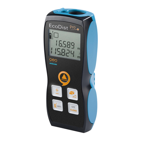
Automation Dr. Nix QNix 1500 User manual

1
Instruction Manual
Coating Thickness Gauge
1500
Optionally with Memory

Introduction
The QNix®1500 is a part of the product line of non-destructive
coating thickness measurement gauges manufactured by
Automation Dr. Nix GmbH & Co. KG in Köln, Germany.
Designed for the future, this gauge is characterized by its
many applications and wide measuring range of up to 5 mm. It
is also characterized by its robust construction as well as by
other advantages already known from our other gauges. An
ON/OFF switch is not necessary, no time-consuming
calibration routines are required, and exchange of probes is
not necessary.
The special design of this gauge facilitates measurements in
hard-to-reach corners, even more so because of the duplex
display and the memory for the last measured value.
Please read these instructions carefully before operating the
gauge for the first time. It will help you to make use of all the
advantages and conveniences this gauge offers.
Would you like information on the other gauges in our coating
thickness measurement line or do you have any questions
concerning coating thickness measurement? Please do not
hesitate to contact us. Our specialists with their long-standing
experience will be happy to assist you.
System Description
The QNix®1500 is a combination coating thickness gauge,
optionally available with memory and interface RS 232. Two
non-wearing probes, Fe-probe and NFe-probe have been
integrated in the housing.
The Fe-probe measures all non-magnetic coatings such as
lacquer, plastic, enamel, chromium, copper, zinc, etc. on steel
or iron. The NFe-probe measures all insulating coatings such
as lacquer, plastic, enamel, etc. on non-magnetic, metallic
substrates, i.e. aluminum, copper, brass or stainless steel.
This compact design without cables and plugs allows for easy
and comfortable one-hand operation thus increasing the
working safety under rough conditions.
The QNix®1500 with memory can store the measurements
taken and even subdivide them into blocks. All in all, up to
2

3900 values can be stored and statistically evaluated.
Optionally, a special software for statistical evaluation can be
supplied.
The QNix®1500 complies with national (DIN) and international
(ISO, BS, ASTM) standards and regulations: DIN 50981,
50984; ISO 2178, 2360, 2808; BS 5411(3, 11), 3900 (c, 5);
ASTM B499, D1400, D7091
Maintenance and Handling
This gauge incorporates the latest electronic technology in
order to fulfill different measuring tasks. This high precision
instrument covers a wide range of applications, yet it is robust
and easy-to use in every-day practice. If operated and treated
with care, it will serve you many years.
Do not let it drop and protect it from dirt, dust and other
substances. After use, the gauge should be stored in its
protective carrying case.
Substantial changes in temperature can influence the
readings, as it is the case with all precision gauges. Do not
expose the gauge to strong, direct sunlight or to other sources
of energy causing temperature shocks.
Protect the gauge from moisture, chemically aggressive
substances and/or gases.
The casing is resistant against most solvents. However, a
resistancy against all chemical substances cannot be
guaranteed. Use only a damp, soft cloth to clean the casing.
Accurate readings can only be obtained, if the measuring
probes are clean. Check the probes regularly and remove
existing residues such as lacquer etc. from the ruby probe tip.
If the gauge will not be used for a long period, remove the
battery in order to prevent leakage and therefore destruction
of the gauge.
In case of a malfunction, please do not try to repair the gauge
yourself. Our repair service will be glad to help at any time.
Measuring Range
0 – 5000 μm or 0 – 200 mil in one measuring range
Gauges without memory can be switched from μm to mil by
operating the two switches on the sides of the instrument.
3

While there is a value visible on the display, push both slides
simultaneously forward and hold for more than one second.
The reading will change to the other dimension.
Gauges with memory can be switched from μm to mil using
the optionally available software.
Resolution
0.1 μm in the range of 0.0 – 99.9 μm
1 μm in the range of 100 – 999 μm
0.01 mm in the range of 1.00 – 5.00 mm
Or
0.01 mil in the range of 0.00 – 9.99 mil
0.1 mil in the range of 10.0 – 99.9 mil
1 mil in the range of 100 – 200 mil
Temperature Range
0 °C - 50 °C or 32 °F - 122 °F
Operating and Changing of Battery
The gauge is powered by a 9V alkaline battery. The battery is
located at the wide end of the gauge. If the blinking sign ”BAT“
appears on the display, it is advisable to change the battery,
but it is still possible to measure for some time. Memorized
data will remain stored, even while changing batteries.
Empty batteries should be disposed separately. If possible,
use the special services provided by your council.
Adjustment and User Information
A new zero-adjustment is required when using the gauge for
the first time, working with different materials, after inserting a
new battery, or from time to time.
Place the respective probe of the QNix® 1500 on one of the
zero plates enclosed in the case. For measurements on
ferrous substrates use the steel zero plate, for non-ferrous
applications the aluminum plate or a respective uncoated
substrate.
4

Hold the gauge according to the drawing and slightly press the
probe onto the surface so that the ring around the probe is
evenly placed. If the value indicated on the zero plate or on
your uncoated substrate is not within the basic tolerance, the
gauge should be adjusted (gauges with a memory must not be
in the Memory Mode). Push one of the slides at the sides of
the gauge while the probe is placed firmly on the substrate, i.e.
the zero plate. You will hear a ”Beep“ and a control number
will appear on the display. Lift the gauge at least 25 mm or
one inch from the zero plate. The gauge will ”beep“ again and
another number will be displayed. The QNix® 1500 is
adjusted now.
When repeating measurements on the same spot, the
measured value may not always be 0.00, due to surface
roughness, dirt, scratches etc.
The gauge is delivered with two protective rings around the
probe for better positioning and protection. These rings can
easily be removed by slightly turning and pulling. On concave
surfaces remove the protective rings in order to achieve
accurate measurements.
Measurement
Place the QNix®
1500 with its ring
around the probe
plane on the
object to be
measured (see
drawing). For
measurements on
steel or iron, the
Fe-sticker should
face you. For
measurements on
non-magnetic metallic substrates such as aluminum you
should be able to see the NFe-sticker.
Do not place your finger on the upper probe, otherwise the
readings will not be correct. Take care that the circular probe
ring is placed evenly on the surface. On even objects, the two
rear supporting points will help to position the gauge. The
5

measured value is immediately indicated on the display
accompanied by a ”Beep“.
The display shows ”ERR“ (error) if the QNix® 1500 is placed
incorrectly and ”INFI“ (infinite) if the measurement is out of
range. The same will be displayed, if measurements on non-
metallic substrates are taken. The gauge turns on
automatically and shuts off after approx. 10 sec., if it is not
used.
When measuring on rod materials remove the red ring and
align the ”V“-groove in the ring of the probe with the rod.
Do not take measurements on magnets. Magnetic fields are
likely to influence the readings with the Fe-probe. Strong
electromagnetic fields may influence all measurements.
Memorizing Measured Values
Optionally, the QNix® 1500 can be delivered with a built-in
memory and an interface RS 232C, offering the following
features:
a) Memory for up to 3900 values
b) Block segmentation up to 999 blocks
Block No. 1 Indication b001
Block No. 2 Indication b002 as up to
Block No. 999 Indication b999
c) Display of the calculatory average value in each block
d) Display of the maximum value in each block
e) Display of the minimum value in each block
f) Deleting the last measured value and the entire memory
g) Processing the measured values using interface and
software
Memory Mode (optional)
To work in the Memory Mode, the gauge has to be switched
on (take any measurement). Push both slides on the sides of
the gauge simultaneously and hold them for approx. 1 second.
Let the slides go. The display will show ”bloc“ alternating with
”b001“. The gauge is now in the Memory Mode and all
following measurements will be stored in Block 1.
Measurements in the Memory Mode will be accompanied by
6

a double ”Beep“ and the value will be displayed. After approx.
1 second, the display changes and gives you the number of
the measurements just taken. Both readings will be displayed
alternately, e.g. the display will show N 14 (number of
measurement) and 124 μm (last measured value).
To leave the Memory Mode, push both slides simultaneously
and very shortly.
Do not hold.
The built-in memory can store up to 3900 measurements. In
case the memory capacity is limited, the display will show
”END“ for approx. 6 seconds. After this, you will see the last
measured value alternating with the number of this
measurement.
If no measurements are taken within 30 seconds, the gauge
will switch off. The gauge will automatically return to Normal
Mode when started again.
Block Segmentation within the Memory
Mode
It is possible to store the measuring values in different blocks,
in order to distinguish the different tasks. To set up a new
block, e.g. Block 2, push both slides simultaneously forward
and hold them until you see the display changing. Let the
slides go. Accompanied by a ”Beep“, the display will show
”bloc“ alternating with b002. Now you have created a new
block and all following measurements will be stored in Block 2.
Other blocks can be created using the same procedure.
The sizes of the blocks may vary as they are determined by
the user only. Within the total capacity of the memory up to
999 blocks can be built. If the memory runs out of space, the
information ”End“ will be shown.
Display of Mean, Maximum and Minimum
Values
Additionally, the gauge can display the mean, maximum and
minimum value of the measurements taken in the presently
used block, if the gauge is switched on and working in the
Memory Mode. Push one of the slides for approx. 1 second
7

and let it go. Immediately, you will see the letters ”AE“ for
”Average“ and a number giving you the number of all
measurements in the respective block. This information is
followed by the display of ”μm“ or ”mil“ and the value itself,
representing the average or mean value of all measurements
taken in the present block. For example, “AE 22” alternating
with “139 μm” means, that in the active block 22
measurements have been taken and stored and that the
average value is 139 μm.
In order to see the maximum value of the active block, again
push one of the slides forward. The display will show and
the maximum value. Pushing one of the slides forward again
you will receive the minimum value of the active block. In
order to leave this mode push one of the slides forward again
or take a measurement.
In case no measurements have been taken in the active block,
it is not possible to get any statistical value. The display will
then read ”AE“. Then the gauge automatically returns to the
memory mode.
Deleting Measured Values
While operating in the Memory Mode, the QNix® 1500 offers
the possibility to delete the last reading on the display and in
the memory as well as the entire memory. To achieve this,
push one of the slides for longer than 3seconds. The last
reading will be deleted. If the slide is held further on the
display shows ”dEL“ and ”ALL“ (alternating) for 3 seconds and
a ”Beep“ sounds. If the slide is not released within these 3
seconds the entire memory will be deleted.
In case all values in a block are already deleted, the next
deleting process will eliminate the block itself, and the last
measurement in the previous block will be displayed.
The entire memory can also be deleted by use of our
optionally available software.
Processing of Memorized Values
The built-in interface RS 232 allows transfer of the data to a
PC to process the measured data statistically. The respective
plug is mounted on one side of the gauge. A software for
8

statistical evaluation on your PC is optionally available.
For further information concerning ”Data Processing“ please
refer to the software.
Possible Display Information
1. Fe = Measurement on steel or iron substrates
2. NFe = Measurement on non-ferrous metallic substrates
3. ERR = Incorrect handling
4. INFI = Incorrect substrate, e.g. measuring beyond the
measuring range or measuring on wood
5. BAT = Battery is getting weak, please exchange.
Information: the measured values will remain
stored.
6. bloc = Displayed alternating with the block number
7. End = Memory or block capacity out of space
8. N = a) alternating with Fe or NFe
= number of measurements
b) alternating with Ae
= number of measurements of the active block
9. Ae = Average value measured in the active block
10.= Maximum value measured in the active block
11.= Minimum value measured in the active block
Accessories
The electronic coating thickness gauge QNix® 1500 is
delivered with a carrying case containing Fe and NFe zero
plates, a 9 V alkaline battery, two probe protection rings and
Instruction Manual.
9

Technical Data
Substrate Fe: steel or iron
NFe: non-ferrous metallic substrates as
aluminum, zinc, copper, brass,
stainless steel
Measuring Range 0.0 – 5000 μm or 0.00 – 200 mil
convertible by slide or by software
Display of Values from 0.0 – 999 in μm
from 1.00 – 5.00 in mm
or from 0.00 – 200 in mil
Resolution 0.1 μm in the range of 0.0 – 99.9 μm
1 μm in the range of 100 – 999 μm
0.01 mm in the range of 1.00 – 5.00 mm
or 0.01 mil in the range of 0.00 – 9.99 mil
0.1 mil in the range of 10.0 – 99.9 mil
1 mil in the range of 100 – 200 mil
Repetitive accuracy ± (1 μm + 2% of reading) in the range
of 0 – 999 μm
+ 3.5% of reading in the range
of 1000 – 5000 μm
Minimum object size 10 x 10 mm2or 0.4" x 0.4"
Minimum curvature 5 mm convex or 0.2"
25 mm concave or 1.0"
Minimum substrate Fe: 0.2 mm or 8 mil
thickness NFe: 0.05 mm or 2 mil
Temperature range storage –10°C – 60°C (14°F – 140°F)
operating 0°C – 50°C (32°F – 132°F)
Display Digital (LCD)
Probes One-point, integrated
Power supply 9 Volt E block alkaline
Dimensions 166 mm x 64 mm x 34 mm
incl. probes (6.5" x 2.5" x 1.3")
Weight 130 g (4.6 oz) incl. battery
Optional: Memory capacity up to 3900 values
Blocks up to 999
Interface RS 232
10

11

03/09
12
Automation Dr. Nix GmbH & Co. KG
Robert-Perthel-Str. 2
50739 Köln, Germany
Tel. +49 (0) 221 91 74 55-0
Fax +49 (0) 221 17 12 21
www.automation.de
Table of contents
Other Automation Dr. Nix Measuring Instrument manuals

Automation Dr. Nix
Automation Dr. Nix QNix 4200 User manual
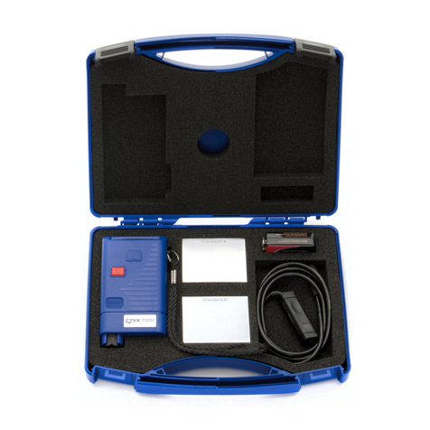
Automation Dr. Nix
Automation Dr. Nix QNix 7500 User manual
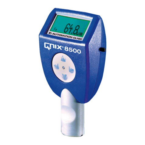
Automation Dr. Nix
Automation Dr. Nix QNix 8500 User manual
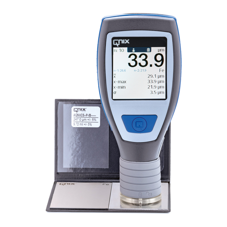
Automation Dr. Nix
Automation Dr. Nix QNix 5500 User manual
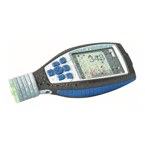
Automation Dr. Nix
Automation Dr. Nix QNix 9500 Series User manual
Automation Dr. Nix
Automation Dr. Nix CarCheck System PLUS User manual

Automation Dr. Nix
Automation Dr. Nix QNix 5500 User manual

Automation Dr. Nix
Automation Dr. Nix QNix 5500 User manual
Automation Dr. Nix
Automation Dr. Nix QNix 9500 Series User manual

Automation Dr. Nix
Automation Dr. Nix QNix 9500 Series User manual
