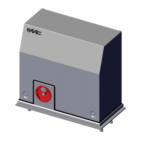
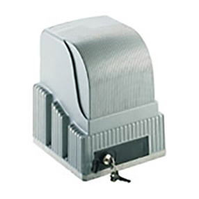
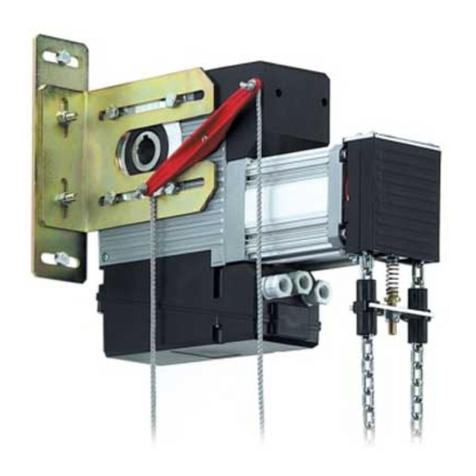
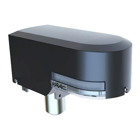
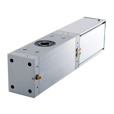
FAAC R180 User manual

ENGLISH
1
INDEX
0 .. DECLARATION OF CONFORMITY AND WARNINGS FOR THE INSTALLER................................................................. 2
1 .. DESCRIPTION AND TECHNICAL SPECIFICATIONS.................................................................................................. 3
1.1 DIMENSIONS........................................................................................................................................................... 3
1.2 MECHANICAL PREPARATIONS ................................................................................................................................. 3
2 .. ELECTRIC PREPARATIONS (standard system) ..............................................................................................................4
3 .. INSTALLING THE AUTOMATED SYSTEM ................................................................................................................. 4
3.1 PRELIMINARY CHECKS ............................................................................................................................................ 4
3.2 INSTALLATION DIMENSIONS .................................................................................................................................... 4
3.3 INSTALLING THE OPERATOR .................................................................................................................................... 4
4 .. TRAVEL LIMIT UNIT ................................................................................................................................................ 6
5 .. ELECTRICAL CONNECTIONS................................................................................................................................. 6
5.1 BUTTON-BOARD OR SELECTOR 230 Vac ................................................................................................................. 6
5.2 COMMANDS WITH 200BT CONTROL BOARD ......................................................................................................... 6
5.3 COMMANDS WITH 200MPS CONTROL BOARD ...................................................................................................... 6
6 .. START-UP OF THE SYSTEM .................................................................................................................................... 7
6.1 MANUAL ADJUSTMENT OF THE TRAVEL-LIMIT DEVICES............................................................................................. 7
7 .. INSTALLING THE ELECTRO-BRAKE (optional) ......................................................................................................... 7
8 .. CONNECTION OF TWO R180/280 UNITS............................................................................................................... 8

ENGLISH
2
CE DECLARATION OF CONFORMITY FOR MACHINES
(DIRECTIVE 98/37/EC)
Manufacturer: FAAC S.p.A.
Address: Via Benini, 1 - 40069 Zola Predosa BOLOGNA - ITALY
Declares that: Operator model R180, R280,
• is built to be integrated into a machine or to be assembled with other machinery to create a machine under the
provisions of Directive 98/37/EC;
• conforms to the essential safety requirements of the following EEC directives:
73/23/EEC and subsequent amendment 93/68/EEC.
89/336/EEC and subsequent amendment 92/31/EEC and 93/68/EEC
and also declares that it is prohibited to put into service the machinery until the machine in which it will be integrated
or of which it will become a component has been identified and declared as conforming to the conditions of
Directive 98/37/EC.
Bologna, 28 February 2007
The Managing Director
A. Bassi
1) ATTENTION! To ensure the safety of people, it is important that you read
all the following instructions. Incorrect installation or incorrect use of the
product could cause serious harm to people.
2) Carefully read the instructions before beginning to install the product.
3) Do not leave packing materials (plastic, polystyrene, etc.) within reach
of children as such materials are potential sources of danger.
4) Store these instructions for future reference.
5) This product was designed and built strictly for the use indicated in this
documentation. Any other use, not expressly indicated here, could
compromise the good condition/operation of the product and/or be
a source of danger.
6) FAAC declines all liability caused by improper use or use other than that
for which the automated system was intended.
7) Do not install the equipment in an explosive atmosphere: the presence
of inflammable gas or fumes is a serious danger to safety.
8) The mechanical parts must conform to the provisions of Standards
EN 12604 and EN 12605.
For non-EU countries, to obtain an adequate level of safety, the
Standards mentioned above must be observed, in addition to national
legal regulations.
9) FAAC is not responsible for failure to observe Good Technique in
the construction of the closing elements to be motorised, or for any
deformation that may occur during use.
10) The installation must conform to Standards EN 12453 and EN 12445.
For non-EU countries, to obtain an adequate level of safety, the
Standards mentioned above must be observed, in addition to national
legal regulations.
11) Before attempting any job on the system, cut out electrical power.
12) The mains power supply of the automated system must be fitted with
an all-pole switch with contact opening distance of 3mm or greater.
Use of a 6A thermal breaker with all-pole circuit break is
recommended.
13) Make sure that a differential switch with threshold of 0.03 A is fitted
upstream of the system.
14) Make sure that the earthing system is perfectly constructed, and connect
metal parts of the means of the closure to it.
15) The automated system is supplied with an intrinsic anti-crushing safety
device consisting of a torque control. Nevertheless, its tripping threshold
must be checked as specified in the Standards indicated at point 10.
16) The safety devices (EN 12978 standard) protect any danger areas
against mechanical movement Risks, such as crushing, dragging, and
shearing.
17) Use of at least one indicator-light (e.g. FAACLIGHT) is recommended
for every system, as well as a warning sign adequately secured to the
frame structure, in addition to the devices mentioned at point “16”.
18) FAAC declines all liability as concerns safety and efficient operation of
the automated system, if system components not produced by FAAC
are used.
19) For maintenance, strictly use original parts by FAAC.
20) Do not in any way modify the components of the automated
system.
21) The installer shall supply all information concerning manual operation
of the system in case of an emergency, and shall hand over to the user
the warnings handbook supplied with the product.
22) Do not allow children or adults to stay near the product while it is
operating.
23) Keep radiocontrols or other pulse generators away from children, to
prevent the automated system from being activated involuntarily.
24) Transit is permitted only when the automated system is idle.
25) The user must not attempt any kind of repair or direct action whatever
and contact qualified personnel only.
26) Maintenance: check at least every 6 months the efficiency of the
system, particularly the efficiency of the safety devices (including, where
foreseen, the operator thrust force) and of the release devices.
27) Anything not expressly specified in these instructions is not permitted.
WARNINGS FOR THE INSTALLER
GENERAL SAFETY OBLIGATIONS

370
60
204
==
400
?
?
Ø 15
ENGLISH
3
AUTOMATED SYSTEM R180 / R280
The following instructions apply to automated systems:
R 180 - R 280
The FAAC automated system for moving rolling shutters consists of a drive
crown gear and a central body including the drive unit, the reduction
components and the travel-limit unit.
The models supplied with an electro-brake guarantee that the lifting
position is maintained if the drive is not perfectly balanced.
Automated systems R180 and R280 are designed for moving rolling
shutters falling within the technical specifications declared by FAAC
manufacturing company. Do not use them for any other purpose.
1 DESCRIPTION AND TECHNICAL SPECIFICATIONS
Tab. 1 - Technical Characteristics of Operator R180 and R280
Model R 180 R 280
Power supply voltage 230 V~ (+6% -10%) 50 (60) Hz
Absorbed Current 2,4 A 4,4 A
Max Drive Torque 180 Nm 280 Nm
Lifting Capacity 180 Kg 280 Kg
Winding Speed 10 rpm 10 rpm
Operating ambient temperature
-40 °C ÷ +55 °C
Shutter Shaft Diameter 60 /48*/42* mm 60 /48*/42* mm
Winding Flange Diameter 200 / 220** mm 200 / 220** mm
Maximum Shutter Height 8 m 8 m
Maximum Shutter Width 4,5 m 4,5 m
Operator Weight 8,7 Kg 12,5 Kg
R.O.T. (at 25°C) 100 sec 120 sec
1.1 DIMENSIONS
1.2 MECHANICAL PREPARATIONS
Drive crown gear
Reduction unit
Single phase motor
Service bracket (DO NOT REMOVE before completion of
installation)
Thrust capacitor
Travel-limit Unit
Power cable
Dimensions in millimetres
Fig. 1
Fig. 2
* use the appropriate reductions included in the standard
supply.
** use the appropriate adapters.
Fig. 3
Dimensions in millimetres
Fully unwind the shutter and find the mid-point of the winding shaft.
As shown in Fig. 3, move to the right of the mid-point by 400 mm and
drill a hole with a diameter of 15 mm. This hole will be used for routing
the power cable and the release cable for the optional electro-brake
device..
Measure the diameters of the pulley and the winding shaft in order to
determine the use of reductions for the securing flange or shims for the
drive transmission crown gear, as explained in chapter 3.3 “INSTALLING
THE OPERATOR”.

Ø 10,5 mm
==
ENGLISH
4
3 INSTALLING THE AUTOMATED SYSTEM
2 ELECTRIC PREPARATIONS (standard system)
3.1 PRELIMINARY CHECKS
To ensure a correctly operating automated system, the structure
of the existing shutter or shutter to be built must satisfy the following
requirements:
• Dimensions and maximum weight as per specifications in Tab. 1.
• Strong, well constructed shutter structure.
• Smooth rise and descent movement, free of any irregular friction along
its entire travel.
• The rotation pins and moving parts must be in good condition.
• Shutter well balanced during its entire travel.
We advise you to carry out the metalwork jobs if any, before installing
the application.
The condition of the structure directly influences the reliability and safety
of the automated system.
3.2 INSTALLATION DIMENSIONS
3.3 INSTALLING THE OPERATOR
Drive unit FAAC R180 / R280
Key operated switch
Electronic control board
Optional electro-brake
Low voltage cable No.1= 3 x 0,5 mm
High voltage cables No.1 2 x 1,5 mm2+ earth
and No. 1 3 x 1,5 mm2+ earth Fig. 4
Fig. 6
Fig. 5
Before taking the necessary measurements, accura-
tely clean the shutter shaft removing deposits of dust,
grease and chips, …
To install two R180 or R280 operators on a shutter
having a width of over 4.5 meters, please refer to
chapter 8 on page 8.
Procedure for defining the correct position of the operator:
Fully unwind the shutter to obtain access to the winding shaft;
As shown in Fig. 5, find the mid-point of the winding shaft and mark
it for subsequent use;
Install the operator, following the instructions in chapter 3.3,
positioning the electric motor on the right of the shaft as shown in
Fig. 5.
1.
2.
3.
During the installation operations, take great care NOT TO
REMOVE the service bracket, ref. Fig.6, in order not to
compromise the initial position of the travel-limit devices.
Install the operator as follows:
Position the operator body on the shaft, with the central part of
the securing flange (ref. of Fig.6) on the mid-point previously
measured in chapter 3.2;
If winding shafts with a diameter of 48 or 42 mm (previously
measured in chapter 1.2) are being used, fit the supplied reductions
as shown in Fig. 6A ref. ;
Close the securing flange with its counterpart in ref.b, using the four
screws in ref. ;
Tighten CAREFULLY the operator on the winding shaft, using the
two pressure screws and relevant lock-nuts in ref. , reducing the
cupling spaces;
1.
2.
3.
4.
Fig. 7
Fig. 6A

ENGLISH
5
Accurately clean the surface of the flange (ref. Fig. 8) making
sure to remove all metallic residue produced by the previous hole
drilling operation;
Fit the two parts of the roller bearing (ref. Fig.8) on the flange, and
correctly join them by pressure, to form a single body;
The closure of the roller bearing on the flange is definitive. Any
subsequent attempt to open it could damage the couplings,
thus compromising their operation.
Do not lubricate the flange and bearing with grease or
equivalent substances to avoid subsequent accumulation of
dust and dirt.
7.
8.
Fig. 8
Assemble the transmission crown gear (Fig.8 ref.) using the two
screws in ref. ;
9.
Fig. 10
Fig. 9
Using the hole on the flange in Fig.7 ref.as a reference, drill a
through hole (diam 10.5 mm) on the winding shaft;
Insert, in the hole you have just drilled, the securing screw in Fig.7
ref., tightening it to rest on the washer and self-locking nut;
5.
6.
If, in chapter 1.2, you have measured a winding pulley diameter
of 220 mm, you must fit the crown adapters, as shown in Fig. 9.
Couple the adapters in the housings on the crown. Fasten the
countersunk screw to firmly secure one of the two adapters on the
crown. Fasten the second adapter with the rounded head screw
in order to anchor the shutter.
Anchoring the crown on the shutter could be the cause
of the loss of the initial positions of the mechanical
travel-limit devices. For this reason, we advise you
NOT TO REMOVE the service bracket, ref. Fig.1 on
page 3.
10.
Drill a hole with a diameter of 10.5 mm on the shutter in
correspondence with the securing hole on the transmission crown
gear. To definitively secure the shutter to the crown use the relevant
rounded head screw and its washer, Fig. 10 ref. .
11.

230 V~
50/60 Hz
230 V~
50/60 Hz
ENGLISH
6
The service bracket (rif. ) allows to freely rotate the screws
of the travel-limit device in order to set the configuration
as per figure 11.
Proceed as indicated below:
When the shutter is fully down, the position of the screws of the travel
limit device, ref. and must be as shown in Fig. 11;
Check if the screw of the closing travel limit device (ref. ), presses
on the closing microswitch (ref.) to engage it (the microswitch
emits a light “CLICK” when it is engaged).
Make sure that the screw of the opening travel limit device
(ref. ) is in contact with the bush (ref.) on the left side. The
opening microswitch (ref.) must not be in contact with the screw
as shown in Fig. 11.
Do not remove the service bracket before completion
of the electric installation of the motor and before
being ready for the first automatic movement of the
shutter.
1.
2.
3.
During installation, the positions of the mechanical travel limit devices
may alter, thus compromising the subsequent automatic procedure for
determining the stop positions of the shutter. For this reason, the position
of the travel limit devices must be checked and, if necessary, adjusted
before starting the application.
Screw of opening travel limit device
Screw of closing travel limit device
Rotation constraint lever
Opening microswitch
Closing microswitch
Reference bush
Service bracket
4 TRAVEL LIMIT UNIT
5 ELECTRICAL CONNECTIONS
The gearmotors for shutters R180 and R280 can be commanded by
direct power, supplied by a 230 VAC selector, or by control boards
200 BT and 200 MPS.
To install two R180/280 units on the same winding
shaft, please refer to chapter 8 on page 8 BEFORE
performing the following electrical connections.
The gearmotor is supplied with a pre-wired power cable with a length of
4 meters. Fit this cable in the hole drilled on the winding shaft (as shown
in chapter 1.2 “MECHANICAL PREPARATIONS”), making it come out from
the side of the winding shaft in which you intend to install the movement
commands or the electrical pull-boxes.
The electronic command received from a
button-board/selector at 230 Vac, can only be used
indoors.
5.1 BUTTON-BOARD OR SELECTOR 230 Vac
The 200BT control board makes it possible to connect two push-buttons
commanded on low voltage (24 Vdc) with dead man logic.
An electronic interlock system prevents simultaneous powering of the
electric motor in the two operating directions.
5.2 COMMANDS WITH 200BT CONTROL BOARD
Neutral
Neutral
Open
Close
Open
Close
Fig. 12
Fig. 11
In the R180 and R280 applications the travel limit devices are integrated
and, therefore, the dedicated connections on the 200BT board must be
short circuited.
In Figure 13 jumper connect terminals 2 and 3 to terminal 1.
For further information on the connection and operation of the 200BT
control board, consult the instructions supplied with the board.
The 200MPS control board makes it possible to manage more control
functions and logics.
To make the connections, consult the instructions supplied with the
board.
5.3 COMMANDS WITH 200MPS CONTROL BOARD
Fig. 13
Make the connections shown below according to the type of
command used.
BLUE or GREY BLUE or GREY

ENGLISH
7
Fig. 16
Fig. 17
Fig. 15
Fig. 14
6 START-UP OF THE SYSTEM
The procedure for the first start-up of the automated system for shutter
winders R180 and R280 is of key importance for correct, automatic
adjustment of the travel limit devices.
The travel limit unit of automated system R180 and R280, was designed
and assembled to allow the travel limit devices to be automatically
positioned with a single opening movement.
Carry out the following procedure:
With the shutter completely closed, remove the service bracket (ref.
fig. 11) from the travel-limit unit;
Command complete opening until the mechanical stop point or
the desired height is reached;
According to the type of electric command used,
make sure that the opening movement is constant
along the entire travel. Do not interrupt the rise motion
until the opening height is reached.
Command a complete closure after having reached the opening
position (determined by travel limit stop or by customer’s choice).
The automatic setting procedure for the travel limit devices has ended;
carry out some movements to check if the opening and closing stop
positions are as required.
To further fine tune these positions, consult paragraph 6.1 “MANUAL
ADJUSTMENT OF THE TRAVEL LIMIT DEVICES”.
1.
2.
3.
6.1 MANUAL ADJUSTMENT OF THE TRAVEL-LIMIT DEVICES
If you wish to modify/fine tune the automatically set opening and closing
positions, proceed as follows:
Take the shutter into its fully closed position, to obtain full access to
the travel limit unit;
1.
As shown in Figure 14, incline downward and keep inclined the
rotation constraint lever (ref. ) to enable release of the travel-limit
devices screws;
Turn the travel-limit devices screws clockwise or anti-clockwise
to anticipate or delay the activation of the opening or closing
microswitches;
Release the rotation constraint lever and perform a few movements
to check the effect of the modifications;
Repeat the procedure till obtaining the motor stop in the required
positions.
2.
3.
4.
5.
Electro-brake assembly procedure:
Fit the supplied cable inside the body of the electro-brake until it
comes into contact with the end ball (Fig.15);
Fit the sheath of the cable until it comes into contact with the
electro-brake body (Fig.15);
1.
2.
Assemble the electro-brake in Figure 16 on the cover of the electric
motor with screws ref. and washers ref., mating the motor shaft
ref.with the electro-brake block;
3.
Use the hole (Ø 15 mm), previously drilled for routing the power
cable, to insert the sheath-cable unit into the shutter shaft (Figure
17). Take care not to bend the sheath too much in order to allow
the cable to freely move inside.
4.
The electro-brake is an accessory that guarantees maintaining the
position of the shutter at whatever height it is left.
In fact, the electro-brake acts on the motor shaft, locking it at the end
of each electric movement, thus ensuring that the shutter cannot
be manually moved or lose its position due to imbalance of the
compensation springs.
7 INSTALLING THE ELECTRO-BRAKE (optional)

MASTER SLAVE
NEUTRAL
===
ENGLISH
8
8 CONNECTION OF TWO R180/280 UNITS
For shutters with a width of over 4.5 meters, we advise installing two R180
or R280 operators at the sides of the shutter as shown in Fig. 20.
Fig. 21
Fig. 20
Perform the installation procedures of both drive units as explained in
chapter 3. At the end of the mechanical installation, refer to the following
procedure:
Remove the service bracket, ref. fig. 11, from both drive units,
and keep it;
When the service bracket has been removed, take
great care NOT TO MOVE the transmission crowns
of the operators in order not to compromise the
positioning of the screws of the travel-limit devices.
Open the cover of both travel-limit units;
Remove the power cable of the SLAVE drive unit and make the
connections as indicated in figure 21;
Close the cover of both travel-limit units and reposition the service
brackets.
Continue the installation performing, only for the MASTER operator, the
instructions given from chapter 5 on page 6.
Therefore the travel-limit devices will be adjusted only on the MASTER unit
as described in chapters 6 and 6.1.
The electro-brake can be installed independently on the MASTER or
SLAVE unit.
1.
2.
3.
4.
Assemble the release knob in Figure 18, taking care to fully fasten
the regulator in ref. ;
Pull the cable and firmly tighten terminal ref. :
- To release the gearmotor, restrain the top of the knob and
rotate the bottom part clockwise;
- To relock the gearmotor, restrain the top of the knob and rotate
the bottom part anti-clockwise;
5.
6.
Remove the cover of the travel limit unit, unfastening the three
visible screws;
Connect the two eyelets coming from the electro-brake to the
terminal-board of the travel limit unit, as shown in Fig.19 ref.
and ;
Close the cover of the travel limit unit.
7.
8.
9.
Fig. 19
Fig. 18
This manual suits for next models
1
Table of contents
Other FAAC Garage Door Opener manuals
Popular Garage Door Opener manuals by other brands

ABON
ABON Ultra S Installation and operating instructions

Micanan
Micanan PRO-LH Installation instructions manual

Chamberlain
Chamberlain LiftMaster 3280cm 1/2 HP owner's manual

SEA
SEA STAR 500 installation manual

Pujol
Pujol SENIOR 1 Digital Series Installation and adjustment instructions

Chamberlain
Chamberlain ARM 1703 Operator owner's manual