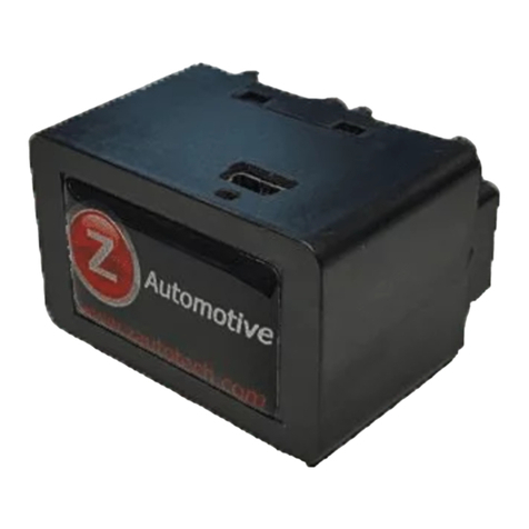
Automotive B-339FD03 User manual

EINBAUANLEITUNG
Installation Guide
Motorweiterlaufschaltung
RunLock
Ford Focus III Gen. (C346) (2011-2018)
für Fahrzeuge mit Automatik- und Manueller Schaltung
for vehicles with automatic and manual shifting
Art. Nr. B-339FD03
10R – 054004
speedsignal GmbH Phone: +49 8061 49518 – 0 E-Mail: info@speedsignal.de
Carl-von-Ossietzky-Straße 3 Fax: +49 8061 49518 – 10 Homepage: www.speedsignal.de
D- 83043 Bad Aibling facebook: facebook.com/speedsignal

B-339FD03_R2 27.03.2020 Seite 2von 7
Sicherheitshinweise - safety instructions
Der Einbau dieses Artikels darf nur von geschultem Fachpersonal vorgenommen werden und nur nach der in dieser
Anleitung beschriebenen Vorgehensweise.
Die speedsignal GmbH übernimmt keinerlei Haftung für Personen- oder Sachschäden, die mit dem Missbrauch unserer
Produkte im Zusammenhang stehen.
Vor der Montage bitte die Batterie abklemmen. Beim Einbau müssen alle zusätzlichen Versorgungsleitungen ent-
sprechend ihres Querschnittes und ihrer Kabellänge abgesichert werden. (DIN VDE 0298-4)
The installation of this product should only be carried out by trained specialist personnel and in accordance with this manual.
speedsignal GmbH cannot accept any liability for injury to persons or damage to property from errors or mistakes in this operating
manual.
Please disconnect the battery before you start with the installation. During montage, all additional supply lines must be secured
pursuant to their cross section and cable length. (DIN VDE 0298-4)
Beschreibung - description
Die Motorweiterlaufschaltung ist eine elektrische Schaltung bei Kraftfahrzeugen, die es ermöglicht, das Fahrzeug bei
laufendem Motor zu verlassen. Eine Fremdnutzung wird durch Sicherheitsmaßnahmen ausgeschlossen. Zusätzlich
kann das Fahrzeug bei laufendem Motor von außen verriegelt werden.
Die Motorweiterlaufschaltung ist in erster Linie für Behördenfahrzeuge in Ausübung ihrer dienstlichen Pflicht vorgese-
hen. Beim Einbau in andere Fahrzeuge als Behördenfahrzeuge weisen wir darauf hin, dass ein unnötiges Laufenlassen
von Fahrzeugmotoren nach §30 I StVO verboten ist.
The RunLock is an electrical circuit in motor vehicles that makes it possible to leave the vehicle while the engine is running.
Safety measures prevent unauthorized use. In addition, the vehicle can be locked from the outside while the engine is running.
Primarily it is intended for the use within authority vehicles in exercise of their duties.
For the installation into other vehicles (not authority) we point out that an unnecessary engine run is forbidden by law in many
countries such as in Germany according to StVO §30.
Lieferumfang – scope of delivery
Interface Runlock-Schaltung (MWS) Kabelsatz mit Zusatzkabel RunLock- Taster
RunLock cable set universal RunLock- button
3470052 C-3470078 6003131
Benötigtes Werkzeug - Required tools
Torxschrauber Ausbauwerkzeug Bohrmaschine Lötkolben
Torx screwdriver removal tool drill soldering irons
Ø 12mm
Torx 20

B-339FD03_R2 27.03.2020 Seite 3von 7
Zusatzkabel einpinnen bei Focus – Pin additional cable at Focus
Blaues Kabel in Pin 3 einpinnen.
Pin blue cable to pin 3.
Abgriffpunkte – tap points
Pin Nr.
Kabelfarbe
Cable colour
Pin 3
blau / blue
3
A
OBD II

B-339FD03_R2 27.03.2020 Seite 4von 7
Abgriffpunkt A für blaue Leitung – tap point a for blue cable
Abgriff OBD II Focus – tap point OBD II Focus
Zu finden im Fahrerfußraum – Rückansicht des OBD II Steckers
Located in the driver's footwell - Rear view of the OBD II connector
+12 V Spannungsversorgung - plus and minus supply
An geeigneter Stelle am Fahrzeug Masse (PIN 1 am Interface) und Stromversorgung
(PIN 7 am Interface) abgreifen.
Die maximale Stromaufnahme des Interfaces beträgt 1 Ampere!
At a suitable location on the vehicle, tap the ground (PIN 1 on the interface) and power
supply (PIN 7 on the interface).
The maximum current consumption of the interface is 1 Ampere!
Bezeichnung
designation
Pin Nr. OBD II
Kabelfarbe Fahrzeug
cable colour vehicle
Pin Nr. Interface
Kabelfarbe Interface
cable colour interface
CAN High
Pin 6
weiß-blau / white-blue
Pin 12
weiß-gelb / white-yellow
CAN Low
Pin 14
weiß / white
Pin 6
weiß-braun / white-brown
Obere Lenkradverkleidung links und rechts ausclip-
sen und untere Verkleidung abschrauben
. Seiten-
verkleidung abnehmen und Verkleidung unterhalb
des Lenkstocks seitlich herausziehen. Stecker lösen
und Abdeckung herausnehmen. Markierter Stecker
befindet sich an der Unterseite des Lenkstocks.
Clip out the upper steering wheel cover left
and
right
and unscrew the lower cover. Remove the
side cover and pull it out laterally underneath the
steering wheel. Loosen the plug and remove the
cover. The marked plug is located on the underside
of the steering wheel.
PIN 1
Belegung Interface
7
1
Originale braun-gelbe Leitung (PIN 1) mit geliefer-
ter
blauen Leitung, technisch einwandfrei am Fahr-
zeug verbinden
.
Original brown
-yellow cable (PIN 1) with supplied
blue cable,
connect technically correct to the vehi-
cle.
Belegung Interface
Belegung Interface
3
16
8
CAN Low
CAN High
1
9
Torx 20

Pin Belegung Kabelsatz Stecker - Pin Assignment Cable set Connector
blau= Verbindung zum Fahrzeug blue = connection to vehicle
Anschlussbelegung 12-poliger Minifit-Stecker
Pin assignment 12-pin Minifit connector
Ein-/Ausgang
Input/output
Bezeichnung
designation
Kabelfarbe am Interface
Kabelfarbe am Fahrzeug
Bemerkung
remark
1
Eingang input
Masse ground
braun brown
Masse ground
2 Ausgang output Masse ground braun brown
Masse RunLock-Taster
ground RunLock button
3 Ausgang output
Zündschalter ignition
switch
blau blue
Pin 1, braun-gelb
Pin 1, brown-yellow
---
4 Ausgang output Output LED grün green
Ausgang +12 V (Anzeige RunLock)
Output +12 V (Display RunLock)
5
nicht belegt not assigned
---
---
---
---
6 Eingang input CAN Low
weiß-braun
white-brown
OBD II Pin 15, braun
OBD II Pin 15, brown
Siehe Seite 6, Abgriffpunkt OBD II
See page 6, tap point OBDII
7 Eingang input
Stromversorgung +12 V
Power supply +12 V
rot red
Anschluss an Klemme 30
Connection to clamp 30
8
nicht belegt not assigned
---
---
---
---
9
nicht belegt not assigned
---
---
---
---
10
nicht belegt not assigned
---
---
---
---
11
nicht belegt not assigned
---
---
---
---
12 Eingang input CAN High
weiß-gelb
white-yellow
OBD II Pin 6, weiß-blau
OBD II Pin 6, white-blue
Siehe Seite 6, Abgriffpunkt OBD II
See page 6, tap point OBD II
Anschlussbelegung 4-poliger Minifit-Stecker
Pin assignment 4-pin Minifit connector
Ein-/Ausgang
Input/output
Bezeichnung
designation
Kabelfarbe am Interface
Kabelfarbe am Fahrzeug
Bemerkung
remark
1
nicht belegt not assigned
---
---
---
---
2
nicht belegt not assigned
---
---
---
---
3Eingang input Taster in
button in
lila purple RunLock-Taster
RunLock button
4
nicht belegt not assigned
---
---
---
---
Belegung Interface
Table of contents
Other Automotive Automobile Accessories manuals
Popular Automobile Accessories manuals by other brands

ULTIMATE SPEED
ULTIMATE SPEED 279746 Assembly and Safety Advice

SSV Works
SSV Works DF-F65 manual

ULTIMATE SPEED
ULTIMATE SPEED CARBON Assembly and Safety Advice

Witter
Witter F174 Fitting instructions

WeatherTech
WeatherTech No-Drill installation instructions

TAUBENREUTHER
TAUBENREUTHER 1-336050 Installation instruction


