TCD210095AB
2 / 3-Phase SSR with
Detachable / Integrated
Heatsink
SR2 / SR3 / SRH2 / SRH3 Series
PRODUCT MANUAL
For your safety, read and follow the considerations written in the instruction
manual, other manuals and Autonics website.
The specications, dimensions, etc. are subject to change without notice for product
improvement. Some models may be discontinued without notice.
Features
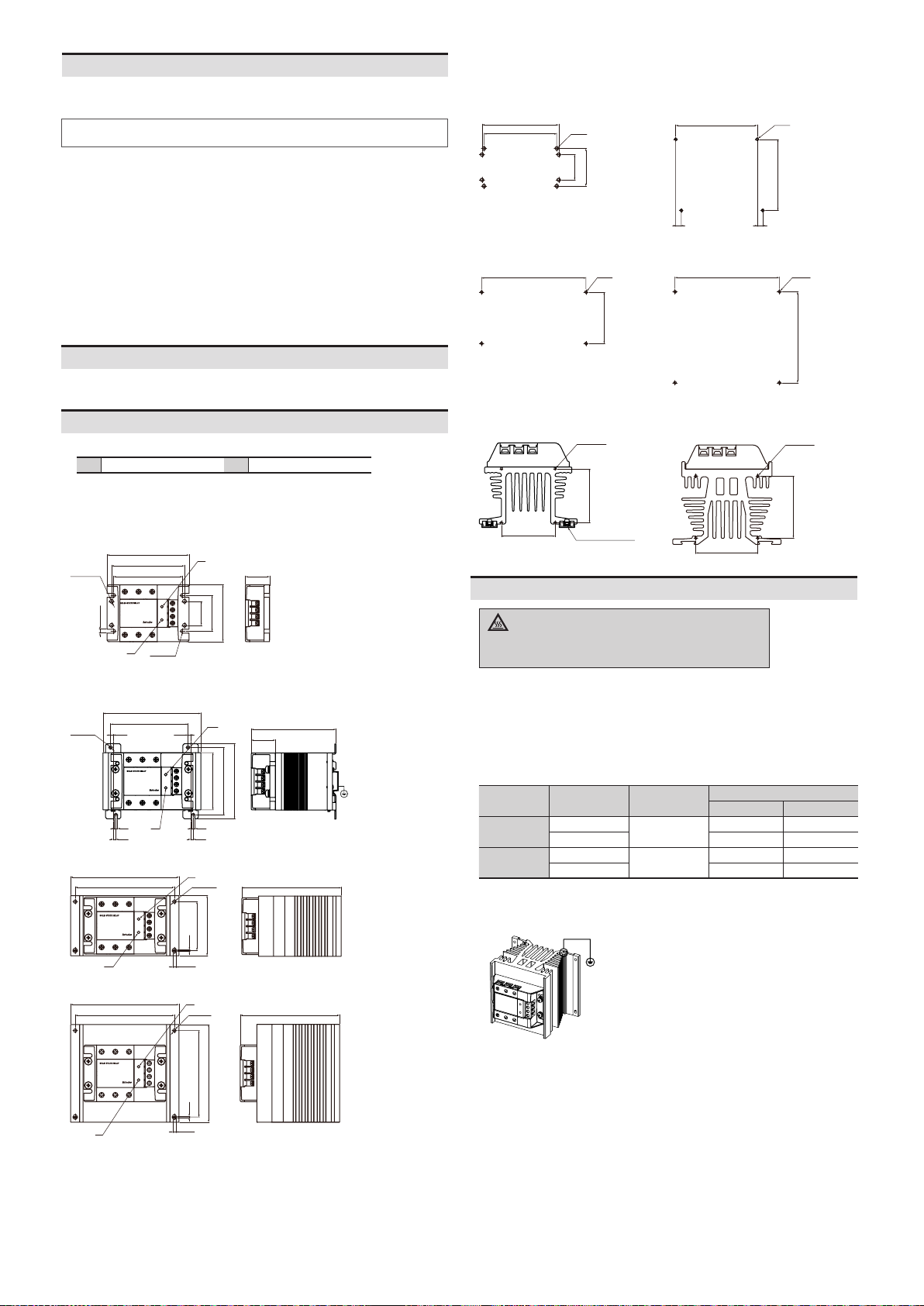
• Two mounting hole types and sizes
• Alarm function (overheat prevention)
: alarm indicator (red), disconnect output, alarm output
• Improved dielectric strength: 4,000 VACᜠ (some are 2,500 VACᜠ model)
• Rated input voltage : 4 - 30 VDCᜡ, 24 VACᜠ, 90 - 240 VACᜠ
• Rated load voltage : 24 - 240 VACᜠ, 48 - 480 VACᜠ
• Rated load current : 15 A, 30 A, 40 A, 50 A, 75 A
• High heat dissipation eciency with ceramic PCB and integrated heatsink
• Zero cross turn-on/Random turn-on models available
• Input indicator (green)
ᜢ ᜧ ᜫ
Safety Considerations
• Observe all ‘Safety Considerations’ for safe and proper operation to avoid hazards.
• symbol indicates caution due to special circumstances in which hazards may
occur.
Failure to follow instructions may result in serious injury or death.
01.
Failure to follow this instruction may result in personal injury, economic loss or re.
02.
Failure to follow this instruction may result in explosion or re.
03.
Failure to follow this instruction may result in re or electric shock.
04.
source.
Failure to follow this instruction may result in re or electric shock.
05.
Failure to follow this instruction may result in re.
06. Do not disassemble or modify the unit.
Failure to follow this instruction may result in re or electric shock.
Failure to follow instructions may result in injury or product damage.
01.
Failure to follow this instruction may result in re or product damage.
02.
Failure to follow this instruction may result in re or electric shock.
03.
into the unit.
Failure to follow this instruction may result in re or product damage.
04.
Failure to follow this instruction may result in electric shock.
• Follow instructions in ‘Cautions during Use’. Otherwise, it may cause unexpected accidents.
• 4 - 30 VDCᜡ, 24 VACᜠ model supply should be insulated and limited voltage/current or
Class 2, SELV power supply device.
• Attach a heat sink or install the unit in the well ventilated place.
To attach the heat sink, use Thermal Grease as below or that of equal specication.
- Thermal Grease: GE TOSHIBA (YG6111), KANTO-KASEI (FLOIL G-600), SHINETSU (G746)
• Ground the heatsink, panel, or DIN rail. Failure to follow this instruction may result in
electric shock.
• While supplying power to the load or right after turning o the power of the load, do not
touch the body and heat sink. Failure to follow this instruction may result in burn due to
high temperature of the surface.
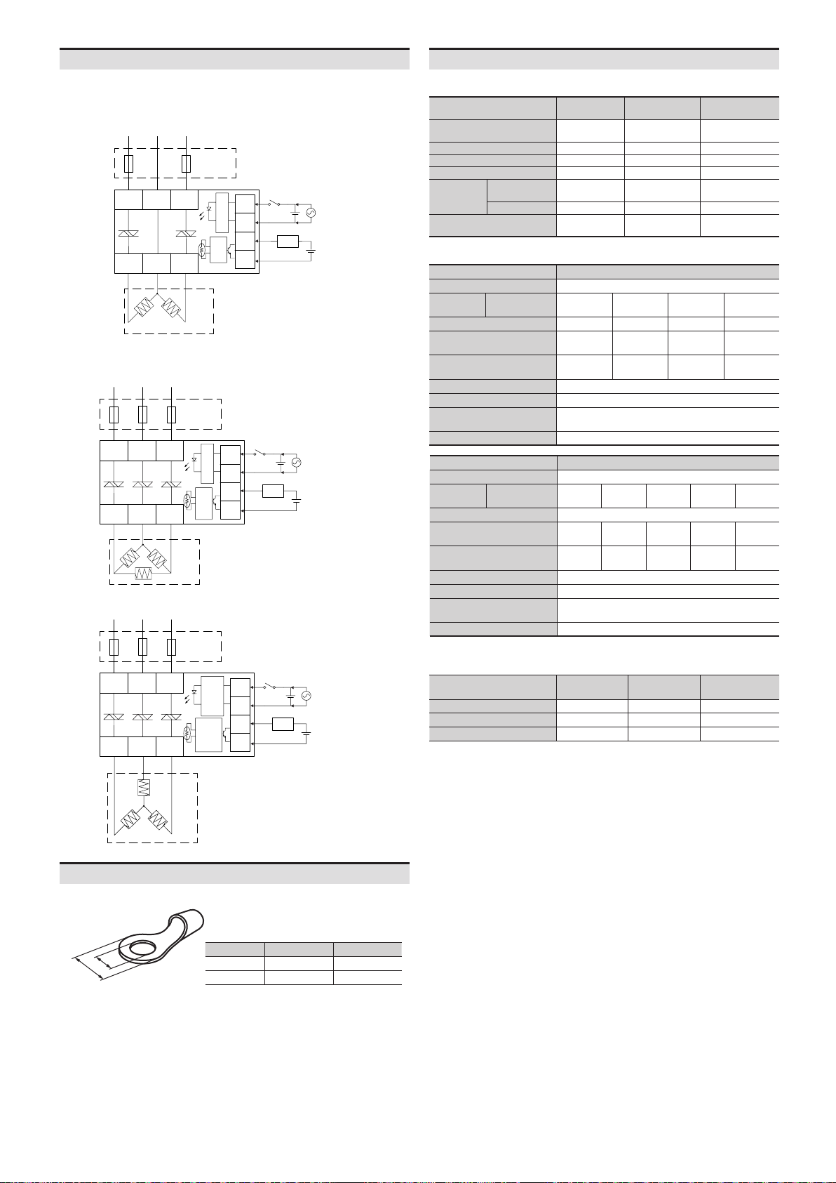
• In order to protect the product from the short-circuit current of the load, use rapid fuse of
which I
2
t is under the 1/2 of SSR I
2
t. When short-circuited, replace the fuse to those of same
specication with the used rapid fuse.
• Install dummy resistance in parallel with the load, to keep the sum of current owing in the
load and dummy resistance being over SSR minimum load current.
• When using random turn-on model for phase control, install noise lter between the load
and the power of the load.
• Do not use near the equipment which generates strong magnetic force or high frequency
noise.
• This unit may be used in the following environments.
- Indoors (in the environment condition rated in ‘Specications’)
- Altitude max. 2,000 m
- Pollution degree 2
- Installation category III