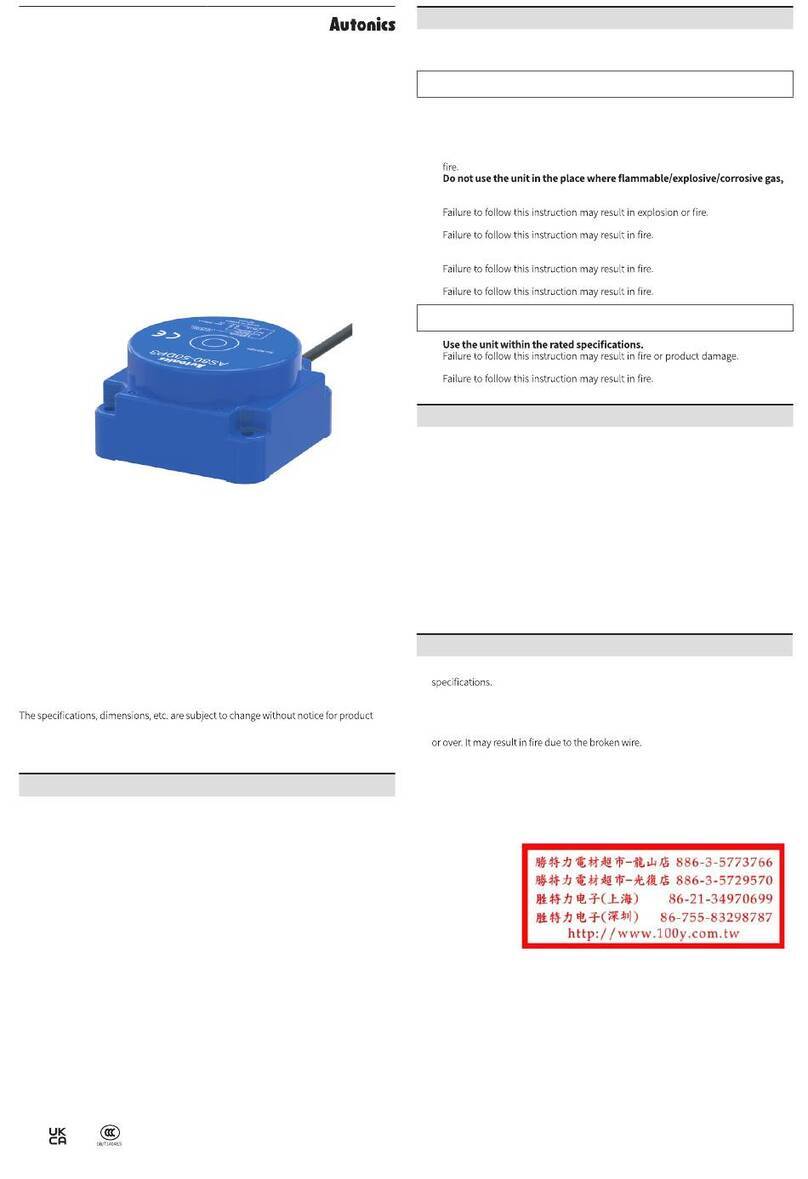
Autonics PR Series User manual

TCD210243AB
Cylindrical Inductive
Proximity Switches
PR Series (AC 2-wire)
PRODUCT MANUAL
For your safety, read and follow the considerations written in the instruction
manual, other manuals and Autonics website.
improvement. Some models may be discontinued without notice.
Features
•Spatter-resistant type
: PTFE coated for high heat resistance (prevent malfunction from welding spatter)
•Operation indicator (red LED)
•IP67 Protection structure (IEC standards)
Cautions for Installation
•Install the unit correctly with the usage environment, location, and the designated
•Do NOT impacts with ahard object or excessive bending of thewire lead-out. It may
cause damage the water resistance.
•Do NOT pull theØ3.5 mm cable with a tensile strength of 25 N,theØ 4 mm cable with
a tensile strength of 30 N or over and theØ5 mm cable with a tensile strength of 50 N
•When extendingwire, use AWG 22 cable or over within 200 m.
SafetyConsiderations
•Observe all ‘Safety Considerations’ for safe and proper operation to avoid hazards.
•symbol indicates caution due to special circumstances in which hazards may occur.
WarningFailure to follow instructions may result in serious injury or death.
01. Fail-safe device must be installed whenusing the unit with machinery that
may cause serious injury or substantial economic loss. (e.g. nuclear power
control, medical equipment, ships, vehicles, railways, aircraft, combustion
apparatus,safety equipment, crime/disaster prevention devices, etc.)
02.
high humidity, direct sunlight, radiant heat, vibration, impact, orsalinity
may be present.
03. Do not disassemble or modify the unit.
04. Do not connect, repair, or inspect the unit while connected to a power
source.
05. Check 'Connections' before wiring.
CautionFailure to follow instructions may result in injury or product damage.
01.
02. Use adry cloth to clean the unit, and do not use water or organic solvent.
03. Do not supply power without load.
Cautions during Use
•Follow instructions in ‘Cautions duringUse’. Otherwise, it may cause unexpected
accidents.
•Wire as short as possible and keep away from high voltage lines or power lines, to
prevent surge and inductive noise.
Do not use near the equipment which generates strong magnetic force or high
frequency noise (transceiver, etc.).
In case installingthe product near the equipment which generates strong surge (motor,
weldingmachine, etc.), use diode or varistor to remove surge.
•Do not connect capacity load to the output terminal directly.
•If the surface is rubbed with ahard object, PTFE coating can be worn out.
•This unit may be used in the following environments.
-Altitude max. 2,000 m
- Pollution degree 2
-Installation category II
ᜢ ᜫ

Product Components
•Product × 1
•Instruction manual × 1
•Nut × 2
•Washer × 1
Sold Separately
•M12 Connector: C□A(H)2-□
•Fixing bracket: P90-R□
•Spatter protection cover: P90-M□
Connections
•LOAD can be wired to any direction.
•Connect LOAD before supplingthe power.
■Cable type
100 -240 VACᜠ
50/60 Hz
LOAD
LOAD
Brown
Blue
■Cable connector type /Connector type
•For LOAD connection, follow the cable type connection.
•Fasten the connector not to shown thethread. (0.39 to 0.49 N m)
•Fasten the vibration part with PTFE tape.
1
4
2
3
Pin Color Function
①- -
②- -
③Blue 100 -240 VACᜠ
50 /60 Hz
④Brown
■Inner circuit
CIRCUIT
LOAD
LOAD
Ordering Information
Thisis only for reference, the actual product does not supportall combinations .
PR ❶❷❸❹ -❺❻❼
❶ Characteristic
No mark: General type
A: Spatter-resistant type
❺ Sensing distance
Number: Sensing distance (unit: mm)
❷Connection
No mark: Cable type
W: Cable connector type
CM: Connector type
❻Power supply
A: 100 -240 VACᜠ
❸ Body length
No mark: Normal
L: Long
❼ Control output
O: NormallyOpen
C: NormallyClosed
❹ DIA. of sensing side
Number: DIA. of sensing side (unit: mm)
Normally open Normally closed
Sensing target Presence Presence
Nothing Nothing
Load Operation Operation
Return Return
Operation
indicator (red)
ON ON
OFF OFF
Operation Timing Chart
Power supply 100 -240 VACᜠ 50 /60 Hz, operating voltage: 85 -264 VACᜠ
Leakage current ≤2.5 mA
Control outputDIA. of sensing side Ø 12 mm:5 to 150 mA
DIA. of sensing side Ø 18 mm,Ø30 mm:5 to 200 mA
Residual voltage ≤10 V
Protection circuit Surge protection circuit
Insulation resistance ≥50 MΩ(500 VDCᜡ megger)
Insulation type
Double insulation or reinfored insulation (symbol: )
dielectric strength between themeasuringinput part and thepower
part: general type 1 kV, spatter-resistant type 1.5 kV
Dielectric strength
General type
: 2,500 VACᜠ 50/60 Hz for 1 min (between the charging part and the case)
Spatter-resistant type
: 1,500 VACᜠ 50/60 Hz for 1 min (between the charging part and the case)
Vibration1 mm double amplitude at frequency 10 to 55 Hz in each X, Y, Z
direction for 2 hours
Shock 500 m/s² (≈50 G) in each X, Y, Z direction for 3 times
Ambient temperature -25 to 70 ℃, storage: -30 to 80 ℃(nofreezing or condensation)
Ambient humidity 35 to 95 %RH, storage: 35 to 95 %RH (nofreezing or condensation)
Protection structure IP67 (IEC standards)
ConnectionCable type / Cable connector type 01)/ Connector type 01)model
Cable spec. 02)DIA. of sensing side Ø 12 mm:Ø4 mm,2-wire
DIA. of sensing side Ø 18 mm,Ø30 mm:Ø5 mm,2-wire
Wire spec.AWG 22 (0.08 mm,60-core), insulator diameter: Ø 1.25 mm
Connector spec.M12 connector
MaterialStandard type cable (black): polyvinyl chloride (PVC)
General Case/Nut: nickel plated brass, washer: nickel plated iron,
sensing side: PBT
Spatter-resistant Case/Nut: PTFE coated brass, washer: PTFE coated iron,
sensing side: PTFE
01) Except spatter-resistant type
02) Cable type: 2 m, cable connector type: 300 mm
InstallationFlush type
General PR□12-2A□PR□18-5A□PR□30-10A□
Spatter-resistant PRA□12-2A□PRA□18-5A□PRA□30-10A□
DIA. of sensing
side Ø12 mm Ø 18 mm Ø 30 mm
Sensing distance 2 mm5 mm10 mm
Setting distance 0 to 1.4 mm0 to 3.5 mm 0 to 7 mm
Hysteresis≤10 % of sensing distance
Standard sensing
target: iron 12 ×12 ×1 mm 18 ×18 ×1 mm30 ×30 ×1 mm
Response
frequency 01)20 Hz
temperature ≤± 10 % for sensing distance at ambient temperature 20 ℃
Indicator Operation indicator (red)
Approval
Installation
General PR□12-4A □PR□18-8A □PR□30-15A □
DIA. of sensing
side Ø12 mm Ø 18 mm Ø 30 mm
Sensing distance 4 mm8 mm15 mm
Setting distance 0 to 2.8 mm0 to 5.6 mm0 to 10.5 mm
Hysteresis≤10 % of sensing distance
Standard sensing
target: iron 12 ×12 ×1 mm 25 ×25 ×1 mm 45 ×45 ×1 mm
Response
frequency 01)20 Hz
temperature ≤± 10 % for sensing distance at ambient temperature 20 ℃
Indicator Operation indicator (red)
Approval
01) The response frequency isthe average value. The standard sensing target is used and thewidth is set as
2 times of the standard sensing target, 1/2 of the sensing distance for thedistance.
Unit weight (package) Ø 12 mm Ø 18 mm Ø 30 mm
Cable Normal≈72 g(≈84 g) 01)≈118 g(≈130 g) 02)≈170 g (≈ 207 g)
Long-≈130 g(≈142 g) ≈208 g (≈ 245 g)
Cable
connector
Normal≈42 g(≈54 g) ≈66 g(≈78 g) ≈122 g (≈ 134 g)
Long-≈78 g(≈90 g) ≈158 g (≈ 195 g)
Connector Normal≈30 g(≈42 g) ≈54 g(≈66 g) ≈142 g (≈ 154 g)
Long-≈66 g(≈78 g) ≈182 g (≈ 194 g)
01) Spatter-resistant type: ≈66 g(≈78 g)
02) Spatter-resistant type: ≈106 g(≈118 g)
Tightening Torque
Use the provided washer to tighten thenuts.
The tightening torque of thenut varies with the distance from the fore-end. [Figure 1]
If thenut tipis located at thefront of the product, apply thefront tightening torque.
the allowable tightening torque table is for insertingthe washer as [Figure 2].
[Figure 1]
Front
Fore-end Nut tip
Rear
[Figure 2]
Washer Mounting side
Sensing
side
Strength
Ø 12 mm Ø 18 mm Ø 30 mm
FlushFlushFlush
Front size 13 mm7 mm--26 mm12 mm
Front torque
6.37 N m14.7 N m49 N m
Rear torque11.76 N m14.7 N m78.4 N m
■Mutual-interference
A
[Face to Face]
B
[Parallel]
■
ℓℓ
n
m
ℓ
Ø d
(unit: mm)
Sensing
side
Item
Ø 12 mm Ø 18 mm Ø 30 mm
FlushFlushFlush
A12 24 30 48 60 90
B24 36 36 54 60 90
ℓ0 11 0 14 0 15
Ø d 12 36 18 54 30 90
m6 12 15 24 30 45
n18 36 27 54 45 90
Setting Distance Formula
Detecting distance can be changed by
the shape, size or material of the target.
For stable sensing, install the unit within
the70% of sensing distance.
Setting distance (Sa)
=Sensing distance (Sn) × 70%
Sa Sa
Sn Sn
Sensing target
: Up-Down movement
Sensing target
: Right-Left movement
Cut-out Dimensions
•Unit: mm, For the detailed drawings, follow the Autonics website.
TAP
HØ 12 mm Ø 18 mm Ø 30 mm
Mounting
hole (H)Ø12.5 +0.5
0Ø18.5 +0.5
0Ø30.5 +0.5
0
TAP M12×1 M18×1 M30×1.5
Ø A
BØ 12 mm Ø 18 mm Ø 30 mm
Ø A 21 29 42
B17 24 35
Sensing Distance Feature Data byTarget Material and Size
Sensing distance (X)
□d
One side
length
■Flush +General type
•Ø 12 mm
2.50
2.00
1.50
1.00
0.50
0.00
Iron (SS401)
SUS364
Brass (C3601)
Aluminum (ALS052)
Copper (C1100)
One side length of sensing target d (mm)
Sensing distance X (mm)
4 8 10 12 15 18 20 25 30 35 40 45 50 60 70 75 80 90 100
•Ø 18 mm
6.00
5.00
4.00
3.00
2.00
1.00
0.00
Iron (SS401)
SUS364
Brass (C3601)
Aluminum (ALS052)
Copper (C1100)
One side length of sensing target d (mm)
Sensing distance X (mm)
4 8 10 12 15 18 20 25 30 35 40 45 50 60 70 75 80 90 100
•Ø 30 mm
12.00
10.00
8.00
6.00
4.00
2.00
0.00
Iron (SS401)
SUS364
Brass (C3601)
Aluminum (ALS052)
Copper (C1100)
One side length of sensing target d (mm)
Sensing distance X (mm)
4 8 10 12 15 18 20 25 30 35 40 45 50 60 70 75 80 90 100

-|Transparent Guide|-
■Flush + Spatter-resistant type
• Ø 12 mm
2.50
2.00
1.50
1.00
0.50
0.00
Iron (SS401)
SUS364
Brass (C3601)
Aluminum (ALS052)
Copper (C1100)
One side length of sensing target d (mm)
Sensing distance X (mm)
4 8 10 12 15 18 20 25 30 35 40 45 50 60 70 75 80 90 100
• Ø 18 mm
Iron (SS401)
SUS364
Brass (C3601)
Aluminum (ALS052)
Copper (C1100)
6.00
5.00
4.00
3.00
2.00
1.00
0.00
One side length of sensing target d (mm)
Sensing distance X (mm)
4 8 10 12 15 18 20 25 30 35 40 45 50 60 70 75 80 90 100
• Ø 30 mm
12.00
10.00
8.00
6.00
4.00
2.00
0.00
Iron (SS401)
SUS364
Brass ( C3601)
Aluminum (ALS052)
Copper (C1100)
One side length of sensing target d (mm)
Sensing distance X (mm)
4 8 10 12 15 18 20 25 30 35 40 45 50 60 70 75 80 90 100
■Non-ush + General type
• Ø 12 mm
One side length of sensing target d (mm)
4.50
4.00
3.50
3.00
2.50
2.00
1.50
1.00
0.50
0.00
Iron (SS401)
SUS364
Brass (C3601)
Aluminum (ALS052)
Copper (C1100)
Sensing distance X (mm)
4 8 10 12 15 18 20 25 30 35 40 45 50 60 70 75 80 90 100
• Ø 18 mm
One side length of sensing target d (mm)
9.00
8.00
7.00
6.00
5.00
4.00
3.00
2.00
1.00
0.00
Iron (SS401)
SUS364
Brass (C3601)
Aluminum (ALS052)
Copper (C1100)
Sensing distance X (mm)
4 8 10 12 15 18 20 25 30 35 40 45 50 60 70 75 80 90 100
• Ø 30 mm
One side length of sensing target d (mm)
16.00
14.00
12.00
10.00
8.00
6.00
4.00
2.00
0.00
Iron (SS401)
SUS364
Brass (C3601)
Aluminum (ALS052)
Copper (C1100)
Sensing distance X (mm)
4 8 10 12 15 18 20 25 30 35 40 45 50 60 70 75 80 90 100

-|Transparent Guide|-
Sensing Distance Feature Data by Parallel (left/right)
Movement
Sensing area (Y)
Sensing distance (X)
Flush type
Non-ush type
■General type
• Ø 12 mm • Ø 18 mm
4.0
3.5
3.0
2.5
2.0
1.7
1.5
1.3
1.0
0.7
0.5
0.4
0.1
Sensing distance X (mm)
4.0 3.0 2.0 1.0 0 0.5 1.0 1.5 2.0
Left ← Center → Right
Sensing area (Y)
Left ← Center → Right
Sensing area (Y)
8.0
6.0
5.0
4.0
3.0
2.0
1.0
Sensing distance X (mm)
8.0 6.0 4.0 2.0 0 2.0 4.0 6.0 8.0
• Ø 30 mm
Left ← Center → Right
Sensing area (Y)
Sensing distance X (mm)
15.0
14.0
12.0
10.0
8.0
6.0
4.0
2.0
20.0 15.0 10.0 5.0 0 5.0 10.0 15.0 20.0
■Spatter-resistant type
• Ø 12 mm • Ø 18 mm
2.0
1.7
1.5
1.3
1.0
0.7
0.4
0.1
Sensing distance X (mm)
Left ← Center → Right
Sensing area (Y)
4.0 3.0 2.0 1.5 0 1.0 2.0 3.0 4.0
5.0
4.0
3.0
2.0
1.0
Sensing distance X (mm)
Left ← Center → Right
Sensing area (Y)
10.0 8.0 6.0 4.0 2.0 0 2.0 4.0 6.0 8.0 10.0
• Ø 30 mm
10.0
8.0
6.0
4.0
2.0
Sensing distance X (mm)
Left ← Center → Right
Sensing area (Y)
10.0 8.0 6.0 4.0 2.0 0 2.0 4.0 6.0 8.0 10.0

-|
Transparent Guide|-
-|Transparent Guide|-
Sold Separately: Fixing Bracket (P90-R )
D
E
C
A
BF
Model
Item (mm)P90-R12 P90-R18 P90-R30
A
B
C
D
E
F
Fixing bolt
Applied sensing side size
Sold Separately: Protection Cover(P90-M )
D C
A
B
Model
Item (mm)P90-M12 P90-M18 P90-M30
A
B
C
D
Applied sensing side size
Sold Separately: M12 Connector Cable
•
Appearance Power Connector 1Connector 2 Length Feature Model
AC
AC
AC
AC
This manual suits for next models
3
Table of contents
Other Autonics Switch manuals

Autonics
Autonics AS Series User manual

Autonics
Autonics ARIO-C-MT User manual

Autonics
Autonics PFI Series User manual

Autonics
Autonics SPB Series User manual

Autonics
Autonics SFDL2 Series User manual

Autonics
Autonics SFDL Series User manual

Autonics
Autonics SFD Series User manual

Autonics
Autonics SF2KR Series User manual

Autonics
Autonics SFEN Series User manual

Autonics
Autonics BEN Series User manual