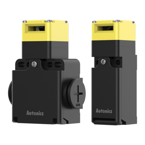
Autonics SFEN Series User manual

-|Transparent Guide|-
TCD210234AE
Safety Grip Type
Enabling Switch
SFEN Series
PRODUCT MANUAL
For your safety, read and follow the considerations written in the instruction
manual, other manuals and Autonics website.
Features
01. Fail-safe device must be installed when using the unit with machinery that may
cause serious injury or substantial economic loss. (e.g. nuclear power control,
medical equipment, ships, vehicles, railways, aircraft, combustion apparatus,
safety equipment, crime/disaster prevention devices, etc.)
02. System manager means followings;
- a personnel who is fully aware of installation, setting, operation, and
maintenance of the product
- a personnel who well observes standard/regulation/statute on the product by
type of machine the product installed in and nation/region the product used
in Machine user means a personnel who is appropriately trained about using
machine by the system manager, so that machine user can operate the machine
correctly.
System manager has duty to train the machine user about operation of the
product.
Machine user has to report directly to the system manager when unusual status
has been found while system is operating.
03. The product has to be installed, set, and combined with machine control system
04. Before using the product, check that function of the product operates as intended
05. This product is a switch used to perform maintenance and repair of machines such
that the machine can only be operated when the switch is operated. Also, do not
maintain position 2 by any means other than manual manipulation.
06.
humidity, direct sunlight, radiant heat, vibration, impact, salinity, moisture, steam
or dust may be present.
07. Do not connect, repair, inspect, or replace the unit while connected to a power
source.
08. Do not disassemble or modify the unit.
09. Do not drop or impact the product.
10. Do not use the door switch with only the holding key inserted.
11.
the holding key insurted into the door switch.
12. Do not defeat, tamper, modify, or bypass the switch and enter the door.
14. Check the installed status of the switch, operating status of the switch, and signs
on a weekly basis.
- when replacing component of the system
- when the system has not been operated for a long time
Safety Considerations
•
•

-|Transparent Guide|-
Product Components
• • •
Sold Separately
•
•
Cautions during Use
•
•
•
•
•
•
•
•
•
01.
02.
into the unit.
03. Use a dry cloth to clean the unit, and do not use water or organic solvent.
04. Do not use the switch as a door lock, guard door stopper or for stopping/starting
machinery.
05.
broken, or foreign substances are introduced, the sealing properties and operation
characteristics may be deteriorated.
06. Use only Autonics holding key.
07.
with the holding key insurted into the door switch.
08. Do not use metallic cable gland.
09.
10. In SFEN-M, when A and B push buttons are pressed at the same time, both
contacts are in the ON status.
Ordering Information
SFEN -
No mark: Standard type B: Stop button type M: Momentary button type
• Enable switch
Rated Insulation
Voltage
Rated through current
Rated inductive load
Rated resistive load01)
Controller strength02)
Operating frequency
Dielectric strength
Electrical life cycle
Machanical life cycle
• Stop button
Rated Insulation
Voltage
Rated through current 3 A
Rated resistive load01)
Controller strength02)
Operating frequency
Dielectric strength
Electrical life cycle
Mechanical life cycle
• Momentary button
Rated Insulation
Voltage
Rated through current
Rated resistive load01)
Controller strength02)
Operating frequency
Dielectric strength
Electrical life cycle
Machanical life cycle
Common spec.
Conditional short circuit
current 100 A
Min. applied load
Directing opening force 30 N ± 10
Directing opening
distance
Insulation resistance
Vibration (malfunction)
Shock (malfunction)
Ambient temperature
Ambient humidity
Insulation class
Indicator
Protection structure
Applicable wire 2
Connection type
Meterial
International standards
Approval
Unit weight (package)
Contact composition
SFEN
Enable switch
Option output
Stop button
Momentary button

-|Transparent Guide|-
Enable Operation Indicator
AC DC
COM
3
4
LOAD
Connections
•
Screw Tightening torque
•
• 2
1
5
2
6
3
7
4
COM
8
L1
L3
L2
•
•
4
Manufacturer Model
JST
Operation Pattern
•
Position 1 (OFF)
Position 2 (ON)
Position 3 (OFF)
•
•
•
•
SFEN
Termianl
number
Position 1 Position 2 Position3
SFEN-B
Termianl
number
Position 1 Position 2 Position3
Termianl
number
Operation Contact
Release
SFEN-M
Termianl
number
Position 1 Position 2 Position3
Termianl
number
Operation Contact
Connecting Cable Gland
•
•
Manufacturer Model Cable Ø
LAPP
Dimensions
•
A B
C D
SFEN
B
A
40
SFEN-B
B
A
40
SFEN-M
B
A
40
DC

-|Transparent Guide|-
•
• Installation
Screw Tightening torque
•
3
• Installation
Surface
Screw Tightening torque
Other Autonics Switch manuals

Autonics
Autonics PFI Series User manual

Autonics
Autonics ARIO-C-MT User manual

Autonics
Autonics PR Series User manual

Autonics
Autonics SF2KR Series User manual

Autonics
Autonics SFDL2 Series User manual

Autonics
Autonics SFD Series User manual

Autonics
Autonics AS Series User manual

Autonics
Autonics SFDL Series User manual

Autonics
Autonics BEN Series User manual

Autonics
Autonics SPB Series User manual