Autonomic Pulsante 5492001 User manual
1
5492001 –Pulsante® SPG Microstimulator System Implant Manual
CONTENTS
1. Welcome . . . . . . . . . . . . . . . . . . . . . . . . . . . . . . . 1
2. Intended Use . . . . . . . . . . . . . . . . . . . . . . . . . . . . 1
3. Symbols . . . . . . . . . . . . . . . . . . . . . . . . . . . . . . . . 1
4. Implant Identification Card . . . . . . . . . . . . . . . . . . 3
5. System Overview . . . . . . . . . . . . . . . . . . . . . . . . . 3
6. Implant Procedure Overview . . . . . . . . . . . . . . . . 6
7. Contraindications . . . . . . . . . . . . . . . . . . . . . . . . . 7
8. Warnings & Precautions . . . . . . . . . . . . . . . . . . . 7
9. Risks & Side Effects . . . . . . . . . . . . . . . . . . . . . . 11
10.Storage & Handling . . . . . . . . . . . . . . . . . . . . . . .12
11.How to Implant the Microstimulator . . . . . . . .13
12.Disposal . . . . . . . . . . . . . . . . . . . . . . . . . . . . . . . 20
13.Technical Specifications . . . . . . . . . . . . . . . . . . .20
14.Information and Support . . . . . . . . . . . . . . . . . . .23
1. WELCOME
Welcome to the Pulsante® family! The instructions in this Manual are intended for physician
implanters of the Pulsante® SPG Microstimulator. Please familiarize yourself with the Implant
Manual, Programming Manual, and Patient Manual prior to using the Pulsante® SPG Microstimulator
System.
2. INTENDED USE OF THE PULSANTE® SPG MICROSTIMULATOR SYSTEM
In the United States, the Pulsante® SPG Microstimulator System is intended to relieve the acute pain
of cluster headache.
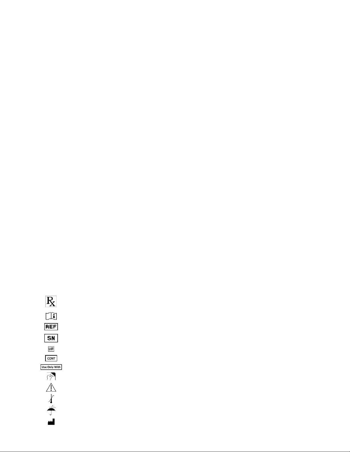
3. SYMBOLS
Symbols and definitions used for the Pulsante® SPG Microstimulator System:
For Prescription Use Only
Consult Operating Instructions
Model Number
Serial Number
Lot Number
Content
Use Only With
Peel Apart
Warning/Precaution
Storage and Transport Temperature Range
Keep Dry
Manufactured By

2
Do Not Do the following
Do not dispose devices in unsorted trash. Dispose devices per local
country regulations for disposing electrical equipment
Do not use device if package is opened or damaged
Date of Manufacture
Use By Date
Symbols and definitions used only for the Pulsante® Microstimulator:
Electrode
Channel
Constant Current
Length
Max Implant Depth
Sterilized using Ethylene Oxide
Content of unopened, undamaged
package is sterile
Single Use
The Pulsante® Microstimulator is MR
Unsafe.
Symbols and definitions used only for the Pulsante® Remote Controller:
Non-Ionizing Radiation
+
–
Power ON/OFF button symbol
Up Button symbol
Down Button symbol
Applied Type B Equipment
USB connector symbol
The Pulsante® Remote Controller is
MR Unsafe. It will be hazardous in all
MRI environments.

3
Press Up or Down Button symbol
Searching For Microstimulator antenna symbol
Recharge Remote symbol
Low Battery symbol
Depleted Battery symbol
Battery Charging symbol
Fully Charged Battery symbol
Alert Indicator symbol
Symbols and definitions used only for the Pulsante® Surgical Tools:
Single Use Only
Sterilized using Ethylene Oxide
Symbols and definitions used for the Pulsante® Programmer Software on Clinician Programmer:
Tilt Symbol indicates that the
selected stimulation amplitude is not
being delivered
Power ON/OFF button symbol
4. PATIENT IMPLANT IDENTIFICATION CARD
A Patient Implant Identification Card is packaged with the Microstimulator. Advise the patient to carry
the identification card at all times. The identification card must be filled out with pertinent patient
information prior to the patient being discharged from the implanting center.
5. PULSANTE® SPG MICROSTIMULATOR SYSTEM OVERVIEW
The rechargeable Pulsante® SPG Microstimulator System (the “System”) electrically stimulates the
sphenopalatine ganglion (SPG) peripheral nerve structure (Figure 1). The rechargeable System
includes a miniaturized Microstimulator, which is placed at the SPG through an incision in the
patient’s gum. The Microstimulator has six electrodes, which are programmed by a trained clinician
using the Programmer Software to customize therapy to the patients’ individual needs. The
Microstimulator is then controlled and powered by a Remote Controller. The patient can use the
Remote Controller to treat their headaches as needed. Periodically, the Remote Controller battery
needs recharging using the Remote Controller Charger provided.

4
Figure 1: Location of the Implanted Pulsante® Microstimulator
The Pulsante® SPG Microstimulator System consists of the following:
Pulsante® SPG Microstimulator
A miniaturized implant with an integral lead, which has six
stimulating electrodes placed near the sphenopalatine
ganglion.
Pulsante® Surgical Tools
Surgical Tools used during implantation of the Microstimulator.
Pulsante® Remote Controller
A rechargeable handheld device used by the patient to activate
and control the Microstimulator. The Remote Controller is also
used by the physician to facilitate adjusting parameter settings
in the Microstimulator.
Remote Controller Charger
The Charger is provided in the Remote Controller packaging
and is used by the patient to charge the Remote Controller.
Pulsante® Programming Software
Software that allows the physician to test and program
stimulation parameters into the Microstimulator and set the
power in the Remote Controller. The Programming Software is
provided on a Clinical Programmer.
Clinician Programmer
Medical-grade tablet that runs the Programming Software. It
includes a Tablet Charger and Programming USB cable.
NOTE: The Microstimulator and Surgical Tools are provided sterile and are sterilized using Ethylene
Oxide.

5
Figure 2: Pulsante® Remote Controller
Front View Side View Bottom View
Figure 3: Pulsante® Microstimulator Figure 4: Remote Controller Charger
Figure 5: Pulsante® Programming Software on Clinician Programmer
COMMUNICATION
DISK (ROUNDED
END OF REMOTE)
UP BUTTON
DOWN BUTTON
USB PORT
DISPLAY SCREEN
POWER BUTTON
(Coin shown for size)
6
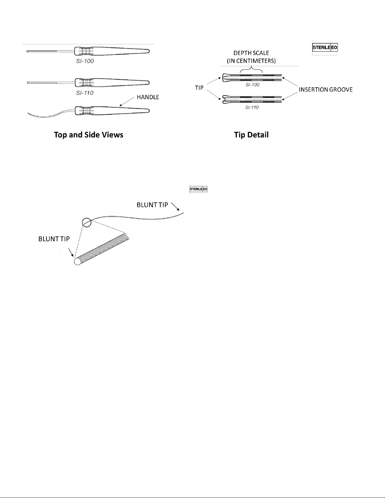
Figure 6: Surgical Introducers 100 & 110
Figure 7: Lead Blank
6. IMPLANT PROCEDURE OVERVIEW
Pre-Operative
Pre-operative facial bone/paranasal sinus Computed Tomography (CT) scan or Magnetic Resonance
Imaging (MRI) may be used for surgical planning and to estimate the appropriate Microstimulator
length for a specific patient. Ensure the patient meets the indications for use.
Intra-Operative
Expose the superior-lateral surface of the zygomaticomaxillary buttress region. Advance the Surgical
Introducer from the superior-lateral buttress to the pterygopalatine fossa along the posterior maxilla.
The Surgical Introducer may be used to estimate the appropriate Microstimulator length by using the
centimeter scale on the medial surfaces of the Surgical Introducer.
The Microstimulator is available in four lengths:
•Short - Approximately 3.6cm in length
•Medium - Approximately 4.4cm in length
•Long - Approximately 5.2cm in length
•Extra-Long - Approximately 6.0cm in length
Use the Lead Blank to create a path for the Microstimulator Lead. Next, remove the Lead Blank and
insert the Microstimulator Lead. Advance the Microstimulator lead into the pterygopalatine fossa

7
using the Surgical Introducer (SI‑100 or SI‑110) as a guide. Remove the Surgical Introducers leaving
the lead in the fossa. Anchor the Microstimulator Body to the anterior zygomatic process of the
maxilla using the Bone Fixation Plate and at least two bone screws.
NOTE: Bone screws are not supplied by Autonomic Technologies.
7. PULSANTE® SPG MICROSTIMULATOR SYSTEM CONTRAINDICATIONS
The Pulsante® SPG Microstimulator System should not be used in patients who have an opening to
the pterygopalatine fossa of less than 1.2mm or have had metal implants or facial surgery in an area
that would prevent proper placement of the Microstimulator.
8. WARNINGS & PRECAUTIONS
WARNINGS
Carefully read all instructions prior to use. Observe all warnings and precautions noted in this Manual.
Implantation
Only physicians with sufficient skill and expertise in the surgical anatomy of the midface, anterior skull
base, pterygopalatine fossa and infratemporal fossa should perform this procedure. Additionally, only
physicians with sufficient skill and expertise in trans-oral surgical techniques, including proper sterile
techniques, should perform this procedure. The surgery is performed under anesthesia, which has its
accompanying risks. Infection may result from the implantation procedure or the implanted device.
Use only specified Pulsante® devices and accessories, specifically the Microstimulator, Remote
Controller, Charger, Surgical Tools and Programmer Software.
Electrostatic Discharge
The integral Microstimulator lead electrodes provide a low-impedance pathway to the Microstimulator
electronics. It is recommended that all healthcare personnel handling the Microstimulator avoid
directly touching the electrodes. Placing the Microstimulator within physiologic saline (only), as
described in the Implant Procedure section, is recommended before handling the Microstimulator.
Diathermy
Diathermy is the use of high-frequency electromagnetic currents as a form of physical therapy in
surgical procedures. Do Not undergo shortwave diathermy, microwave diathermy, or therapeutic
diathermy. Diathermy may cause damage to the tissue near your Microstimulator. Patients should be
advised to contact their doctor before undergoing diathermy.
Magnetic Resonance Imaging (MRI)
The Pulsante® System is MRI Unsafe. Patients should be advised to contact their doctor before
undergoing MRI.
Chronic SPG Stimulation
The effects of chronic SPG stimulation on peripheral nerve structures are not known. In addition, the
effect of chronic SPG stimulation on cognitive function is not known. Patients should be advised to
contact their doctor if they experience any unusual symptoms that they think may be related to the
Microstimulator. If you decide that the System is not providing the therapy needed, it may be left
implanted and not used for stimulation or will require additional surgery to be explanted.

8
Procedures of the Pterygopalatine Fossa
The SPG is located within a space behind your nose called the pterygopalatine fossa. This is where
part of your Microstimulator is implanted. The effects of other procedures on the Microstimulator in
this area are not known. Permanent damage to the Microstimulator may result from these
procedures. Procedures in this area include intra-nasal thermocoagulation and procedures to the
SPG, maxillary branch of the trigeminal nerve, vidian nerve or other neurovascular structures. NOTE:
Inform your doctor of the implanted Microstimulator before undergoing any procedure in the
pterygopalatine fossa.
Electrocautery / Electrosurgery
The use of electrocautery or electrosurgery may cause damage to the Microstimulator, particularly if
used in close proximity to the Microstimulator electrodes. To ensure proper functionality, interrogate
the Microstimulator and perform an electrode impedance test.
Electrical Therapies and Diagnostic Imaging
The effects of certain electrical therapies and diagnostic imaging on the Microstimulator are not well
understood. If you require such treatment, your doctor should consult Autonomic Technologies for
current information on how electrical therapies and diagnostic imaging could affect your device.
Electrical therapies and diagnostic imaging include, but are not limited to: nuclear imaging (for
example, PET Scans), brachytherapy, therapeutic radiation stereotactic radiosurgery,
electroconvulsive therapy, lithotripsy, therapeutic ultrasound, transcranial magnetic stimulation, bone
growth stimulators, and electrolysis. Do Not use your Remote Controller to apply therapy while
undergoing any electrical therapy or diagnostic imaging procedure.
Explosive or Flammable Gases
Do Not use your Remote Controller in an environment where explosive or flammable gases are
present.
Other Patient-Controlled Medical Devices
Do Not place the Remote Controller over other implantable devices (for example, pacemaker,
defibrillator, another neurostimulator). The Remote Controller may accidentally change the operation
of another device. Do not place another device’s transmitter over the Microstimulator. It may
accidentally disrupt the operation of the Microstimulator.
Exposure to Moisture
Do Not use your Remote Controller to activate your Microstimulator while showering, swimming, or
during other activities where the Remote Controller may get wet. The Remote Controller is not
waterproof and should be kept dry to avoid damage.
PRECAUTIONS
Pulsante® SPG Microstimulator System Failure
Although it is unlikely, the System may unexpectedly malfunction, as does any implantable electronic
device. Autonomic Technologies has completed extensive testing under worst-case conditions to
develop and manufacture high-quality devices. However, malfunctions may be caused by things that
cannot be predicted and may result in the device not working and the need for additional surgery. If a
malfunction occurs, then your Remote Controller may not be able to wirelessly connect with your
Microstimulator or your Microstimulator may not deliver therapy.
Lack of Therapy
The communication between the Remote Controller and the Microstimulator is based on many
factors, including orientation and distance between the two devices. Swelling near the incision and/or

9
implant location may prevent communication between the Remote Controller and the implanted
Microstimulator, and therapy may not be possible. If the distance between the devices is greater than
2.5cm, the Remote Controller may not be able to communicate with the Microstimulator. If it is difficult
to establish communication with the Microstimulator, re-evaluate the implant depth specified in the
Programming Software.
Lead Tip Migration
The Microstimulator Lead may migrate from its initial implant location. Lead migration may result in
changes in SPG Microstimulator System effectiveness and the need for additional surgical
procedures. To help minimize the chance of lead migration, care should be taken not to put excess
pressure on the implant location, especially in the immediate post-operative period. For example,
oxygen masks should be avoided in favor of intranasal oxygen.
Prior Surgical Procedures
Prior surgical procedures of the mid-face or anterior skull base may affect the proper implantation of
the Microstimulator. In addition, any metallic objects implanted in the mid-face may cause
interference with the SPG Microstimulator System. Physicians should assess these patients prior to
implanting the Microstimulator to determine if the proper implantation and usage of the SPG
Microstimulator System can be accomplished. Tooth fillings will not interfere with the System.
Post-Implant Medical Tests and Procedures
Medical procedures, devices or tests may damage or alter the SPG Microstimulator System. The
following procedures or tests should only be performed and the following devices should only be used
if the benefits outweigh the risks: facial nerve blocks (e.g., infra-orbital or maxillary), orthodontic or
dental procedures (e.g., tooth extractions or bridge implants), cosmetic procedures (e.g., lipectomy,
face lift, radiothermoplasty, laser skin removal, resurfacing or dermal fillers), and electrohydraulic
lithotripters.
The following procedures or tests should only be performed and the following devices should only be
used after talking to a doctor: facial nerve blocks (for example, infra-orbital or maxillary), orthodontic
or dental procedures, and cosmetic procedures.
Therapeutic Radiation
Therapeutic radiation may damage the electronic circuitry of the System. Sources of therapeutic
radiation include, but are not limited to: therapeutic x-rays, cobalt machines, and linear accelerators. If
radiation therapy is required, the area over the implanted device should be shielded with lead.
Implantable and External Devices
The interaction between the SPG Microstimulator System and other medical devices, including
pacemakers, defibrillators, neurostimulators, hearing aids and other implantable and external devices,
has not been characterized. If the patient requires such devices, the physician should consult
Autonomic Technologies for current information concerning the compatibility of such devices.
Cardiac Defibrillation/Cardioversion
The effect of internal or external defibrillation or cardioversion on the implanted Microstimulator is not
known. If a patient undergoes defibrillation, they should see their doctor to confirm their
Microstimulator settings before using their Remote Controller.
Electromagnetic Interference (EMI)
Certain commercial electrical equipment (for example, arc welders, induction furnaces, resistance
welders), communication equipment (for example, microwave programmers, linear induction motors,
linear power amplifiers, high-power amateur transmitters, and cellular phones), and high-voltage

10
power lines may generate sufficient EMI to cause paresthesia (a sensation of tingling, pricking or
numbness in the face) or interfere with the System. If a patient is uncomfortable or unable to apply
therapy when near such equipment, the patient should move away from the area of EMI. The system
has been designed to fail safely so strong EMI could prompt the Remote Controller to turn off.
Interaction with Electronic Systems
How the System interacts with other electronic devices including RFID systems (particularly within the
121 kHz to 130 kHz range) is not fully understood. Patients should not use the Remote Controller
close to other electronic devices, particularly keyless entry FOBs or near automobile electronics. The
strong electromagnetic fields from the remote controller can disrupt electronic systems that are close by.
Interaction with Metallic or Magnetic Objects
Using the System close to metal or magnetic objects (for example, heavy metal jewelry, metal
headphones, magnetic earrings) may prevent your Remote Controller from communicating properly
with your Microstimulator, especially if that metal object is between the Remote Controller and the
patient’s cheek. If the patient is unable to apply therapy when you are near such objects, have the
patient move away from the object and try again. Metallic objects in the mouth (for example, a metal
retainer) may get warm if they are not removed prior to applying therapy. For clarification, the Remote
Controller is safe to use with tooth fillings.
Handling of the Pulsante® Remote Controller
Use care when handling your Remote Controller. The Remote Controller is a sensitive electronic
device that may be damaged by rough handling, including dropping on the ground or being crushed.
Store the Remote Controller in a cool, dry place. Excess heat can reduce the battery life of the
Remote Controller considerably (for example, patients should not leave the Remote Controller in a
car or under direct sunlight for long periods of time).
Charging the Pulsante® Remote Controller
Only use the Charger provided in the Remote Controller packaging to charge the Remote Controller.
Use of non-Pulsante® charging equipment to charge the Remote Controller can damage the Remote
Controller.
Scuba Diving or Hyperbaric Chambers
Patients should not dive below 30 meters (98 feet) of water or enter hyperbaric chambers above 4.0
atmospheres absolute (ATA), as greater pressures may damage your Microstimulator. Before diving
or using a hyperbaric chamber, patients should discuss the effects of high pressure with their
physician. Also, patients should leave the Remote Controller in a cool, dry play—they should not use
the Remote Controller while swimming or diving.
Excess Pressure or Trauma
Patients should avoid putting excess pressure on the Microstimulator and avoid trauma to that area.
Playing certain contact sports (for example, boxing) may damage the System or change how well it
works with their headaches. If a patient experiences excess pressure or trauma to the area around
your Microstimulator, they should contact their physician.
Pregnancy
The safety and effectiveness of this therapy have not been established for pregnancy, unborn fetus,
or delivery.
Pediatric
The safety and effectiveness of this therapy have not been established for patients under the age of
18.

11
9. RISKS AND SIDE EFFECTS
Please discuss the risks and benefits with your doctor to determine if the device is right for you. Risks
of neurostimulation therapy can include surgical risks, possible side effects, or device complications.
Your doctor can provide more information about these and other potential risks. Please follow your
doctor’s instructions after surgery to minimize surgical risk.
Similar to other oral procedures, most patients will experience some or all of the following effects
post-surgery and most effects resolve within 60 days:
•Sensory and/or motor dysfunction, including numbness, other sensations, and/or facial paresis
(slight or incomplete paralysis)
•Post-operative pain, swelling and/or tenderness at the surgery site
Other risks of surgery may include:
•Seroma/Hematoma (a collection of serum/blood in the body)
•Abcess
•Bruising
•Permanent numbness and other sensations
•Dry eye and tearing
•Trismus (lockjaw)
•Itching
•Pain in the area of the implant
•Infection
•Bleeding
•Facial asymmetry
•Allergic response to implanted materials
•Headache
•Penetration of the sinus wall
•Increased severity/frequency of cluster headaches
•Post-operative nausea or emesis (vomiting)
•Nose bleed
•Ear or nasal fullness/rhinorrhea (nasal discharge)
•Taste alteration
Possible side effects of SPG stimulation include:
•Discomfort or pain during stimulation associated with paresthesia (a sensation of tingling,
pricking or numbness in the face)
•Runny nose
•Dry eye and tearing
•Conjunctivitis
•Headache
Device complications may include:
•Microstimulator migration or misplacement potentially leading to explant and/or re-implant
•Inability of the Remote Controller to connect with the Microstimulator
•Device malfunction
•Skin and/or bone erosion around the Microstimulator implant site

12
10. PACKAGING, STORAGE AND HANDLING
Pulsante® SPG Microstimulator
•The Microstimulator is provided sterile. The Microstimulator is sterilized using ethylene oxide.
•Do not excessively bend the Microstimulator Lead or Bone Fixation Plate. Excessive bending
may damage the integrity of the Microstimulator and may affect device performance.
•Do not attempt to reuse or re-sterilize the Microstimulator. The Microstimulator is intended for
single use only.
•Do not use the Microstimulator if the current date is beyond the labeled “Use by” date.
•Do not use the Microstimulator if the packaging or its contents are damaged or have been
previously opened.
•Do not store the Microstimulator packaging where it may be exposed to water or other liquids,
as moisture may damage the seal integrity of the package materials.
•Store the Microstimulator between –10°C (–14°F) and +55°C (+131°F); temperatures outside
of this range may damage components.
Pulsante® Surgical Tools
•The Surgical Tools are provided sterile. The Surgical Tools are sterilized using ethylene oxide.
•Do not attempt to reuse or re-sterilize the Surgical Tools after surgical use. The Surgical Tools
are intended for single use only.
•Do not use the Surgical Tools if the packaging or its contents are damaged or have been
previously opened.
•Do not store the Surgical Tools’ packaging where it may be exposed to water or moisture.
Pulsante® Remote Controller
•Do not sterilize the Remote Controller.
•Do not store the Remote Controller where it may be exposed to water or other liquids, as
moisture may damage the integrity of the package materials or damage the Remote Controller.
•Do not use the Remote Controller if the packaging or the Remote Controller look damaged.
•The Remote Controller is a sensitive electronic device that may be damaged by rough
handling, including dropping on the ground or being crushed.
•The Remote Controller can be safely stored and operated between 5°C and 40°C. The
Remote Controller can be transported between 20°C and +70°C. Temperatures outside of this
range may reduce battery life.
•Do not connect the USB Port to any other electrical device other than the Charger provided
with the Remote Controller or the Programming USB cable provided with the Programmer
Software.
•The Remote Controller may feel warm when providing therapy. If the patient experiences
discomfort, recommend moving the Remote Controller away from the face slightly and avoid
contact with skin.
•The Remote Controller should not come into contact with skin that is cut or bleeding.
Clinician Programmer
•Do not sterilize the Clinician Programmer.
•Do not store the Clinician Programmer where it may be exposed to water or other liquids, as
moisture may damage the integrity of the package materials or damage the Clinician
Programmer.
•Do not use the Clinician Programmer if the packaging or the Clinician Programmer look
damaged.

13
•The Clinician Programmer can be safely stored and operated between 5°C and 40°C. The
Clinician Programmer can be transported between 20°C and +70°C. Temperatures outside of
this range may reduce battery life.
•Do not connect the USB Port to any other electrical device other than the Tablet Charger or
Programming USB cable provided with the Clinician Programmer.
11. OPERATOR’S INSTRUCTIONS: HOW TO IMPLANT THE MICROSTIMULATOR
A. Personnel Training
Physicians performing the Microstimulator implant should be experienced in the surgical
anatomy of the mid-face, anterior skull base, pterygopalatine fossa and infratemporal fossa.
Physicians should be trained on the use of all components of the Pulsante® SPG
Microstimulator System and the contents of this Manual before initiating the procedure.
B. Planning for Surgery
Implant laterality is selected based on the patient’s predominant side of headache pain.
Choose an appropriate Microstimulator size based on the laterality. Using a pre-operative
facial bone/paranasal sinus Computed Tomography (CT) scan to complete a 3D rendering of
the surgical anatomy and subsequent surface measurement can provide an estimate of the
appropriate Microstimulator length. Alternatively, you can estimate the appropriate
Microstimulator length during the implant procedure by using the scale on the Surgical
Introducers as detailed in Section F below. The Microstimulator is provided in four lengths,
excluding the integral Bone Fixation Plate:
•Short - Approximately 3.6 cm in length
•Medium - Approximately 4.4 cm in length
•Long - Approximately 5.2 cm in length
•Extra-Long - Approximately 6.0 cm in length
The following items are supplied by Autonomic Technologies:
•Microstimulator
•Surgical Tools
•Remote Controller with Remote Controller Charger
•Programmer Software on a Clinician Programmer with Tablet Charger and
Programming USB cable
The following accessories are not supplied by Autonomic Technologies and will need to be
available at the implanting facility:
•Craniomaxillofacial surgical equipment, specifically including:
▪Midface periosteal elevator
▪Craniomaxillofacial bone kit including self-tapping bone screws (1.8 mm diameter
and 4mm length) and the associated driver
•Sterile wand cover/ultrasound probe cover, or other sterile cover as appropriate for
intra-operative use of the Remote Controller
•Sterile plastic basin with sterile saline
•Imaging equipment, such as fluoroscopy.
Observe all oral pre-operative standard-of-care procedures.
14
C. Preparing Devices
Assess the tips of the Surgical Introducers to determine which one(s) will be used for the
procedure.
Prior to placing the Microstimulator, place the Microstimulator in physiologic saline inside a
sterile plastic basin away from a metal surface with the Microstimulator Lead completely
submerged. Complete an interrogation of the Microstimulator and perform an electrode
impedance test to ensure proper functionality as detailed in Section 11, Part H.
Next, bend the Microstimulator Bone Fixation Plate appropriately to the surgical anatomy by
holding the body with your fingers and using a tool. The Bone Fixation Plate bend should
reflect the following target Microstimulator placement:
•The Microstimulator body should lie flat against the posterior maxilla bone, medial to the
zygoma.
•The Microstimulator lead should be positioned within the superior medial
pterygopalatine fossa (PPF) using a lead trajectory that is inferior to superior within the
PPF. This position and trajectory should ensure that at least one electrode is in close
proximity to the SPG.
•The Microstimulator Bone Fixation Plate should be positioned sub-periosteally over the
anterior zygomatic process of the maxilla.
D. Make an Incision
Using standard oral surgical techniques make a 1.0-1.5cm incision located 3–5 mm superior to
the mucogingival junction above the maxillary first or second molar and carried through the
maxillary periosteum (Figure 8).
Figure 8: Incision Location
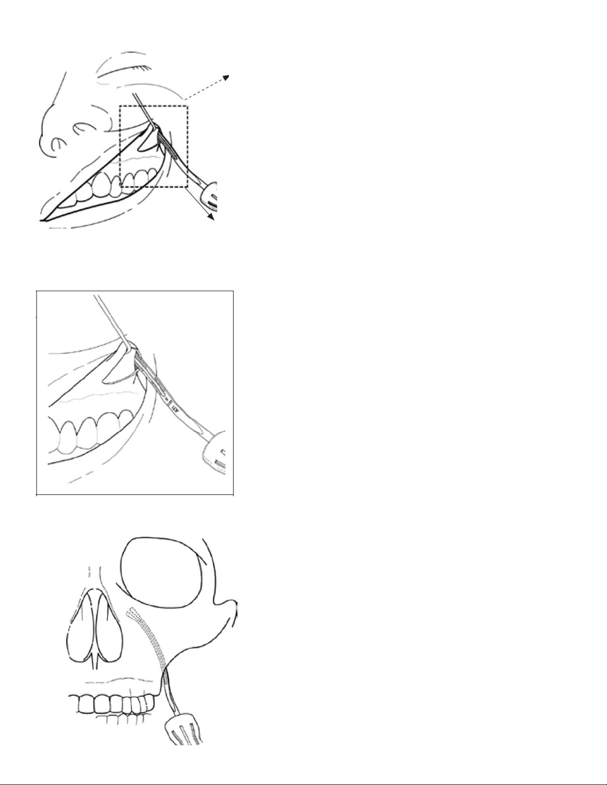
E. Dissect to Target Anatomy
Elevate the maxillary periosteum superiorly and laterally to accommodate the Microstimulator’s
Bone Fixation Plate and to expose the edge of the zygomaticomaxillary buttress (Figure 9 and
Figure 10). Limiting the amount of periosteal elevation may improve post-surgical side effects
from the implantation procedure.

15
Figure 9: Initial Dissection
Figure 10: Initial Dissection Detail
Using fluoroscopy or other visualization, advance the Surgical Introducer from the posterior-
lateral edge of the zygomaticomaxillary buttress towards the pterygopalatine fossa (PPF) using
gentle pressure (Figure 9). The Surgical Introducer is advanced along the posterior maxilla
until the distal tip of the Surgical Introducer is within the pterygomaxillary fissure, or just within
the PPF.
Care should be taken to avoid injury to the infra-orbital nerve during the procedure.
Surgical Introducers 100 and 110 differ in the design of the distal tip. Both tips are designed to
maintain contact with the posterior maxilla during the procedure. However, model 110 is
designed to promote guidance of the Microstimulator Lead into the PPF, if needed.
•Do not apply excessive force to the Surgical Introducer when advancing along the
posterior maxilla. Puncture of the sinus wall can occur.
•Do not advance the Surgical Introducer beyond the pterygopalatine fossa. Patient injury
or poor outcomes may result from further advancement of the Surgical Introducer.
•NOTE: Surgical Introducer placement at the pterygomaxillary fissure or just within the
PPF may be confirmed using standard intra-operative imaging (e.g., fluoroscopy).
16
Figure 11: Inserting the Surgical Introducer
Figure 12: Close-Up View of the Surgical Introducer Inserted
Figure 13: Example Anterior-Posterior Fluoroscopy Image of Surgical Introducer Placement

17
If the Microstimulator size was not chosen beforehand, then it can be chosen during the
procedure. To do so, estimate the appropriate Microstimulator length by using the centimeter
scale on the medial surface of the Surgical Introducers (Figure 6 and Figure 12) once it is
positioned correctly at the pterygomaxillary fissure or within the PPF (Figure 13). This can be
done by reading the distance from the start of the scale on the proximal portion of the Surgical
Introducer to the posterior-lateral edge of the zygomaticomaxillary buttress, and subtracting the
distance from 6.0 cm. Each solid/clear segment of the Surgical Introducer scale represents 0.5
cm.
EXAMPLE: The distance from the proximal portion of the scale to the buttress is three
solid/clear segments (1.5 cm). The estimated Microstimulator length is then 4.5cm, which is
the equivalent of 6.0cm less 1.5cm (Figure 12). In this example, the physician may choose the
medium size of Microstimulator. The Microstimulator length does not include the integral Bone
Fixation Plate.
The distal tip of the Surgical Introducer, when placed properly, is located at the
pterygomaxillary fissure or just within the pterygopalatine fossa. The Lead Blank is used to
create an implant path beyond the tip of the Surgical Introducer within the pterygopalatine
fossa for the Microstimulator Lead. Surgical Introducers include an Insertion Groove (Figure 6)
along the medial surface. Track the Lead Blank along the Insertion Groove on the Surgical
Introducer (Figure 14). Using gentle pressure, advance the Lead Blank along the Insertion
Groove beyond the distal tip of the Surgical Introducer into the pterygopalatine fossa (Figure
15). The Lead Blank has a spherical tip and a flexible shaft that can be used to create an
implant path within the soft tissue of the pterygopalatine fossa. An inferior to superior implant
path or trajectory (Figure 15), starting at the inferior portion of the PPF and progressing
superiorly and medially within the PPF may be associated with better therapy. Implant
trajectories that are more lateral to medial within the PPF are associated with reduced
outcomes compared to inferior to superior trajectories. The Lead Blank is approximately the
same diameter as the Microstimulator Lead.
Figure 14: Advancing the Lead Blank in the Surgical Introducer Insertion Groove

18
Figure 15: Example Fluoroscopy View of the Lead Blank Extended Beyond the Surgical Introducer
Within the Pterygopalatine Fossa
•Do not apply excessive force to the Lead Blank when advancing into the pterygopalatine fossa.
•Do not advance the Lead Blank beyond the pterygopalatine fossa. Patient injury or poor
outcomes may result from further advancement of the Lead Blank.
•Care should be taken to confirm that the distal tip of the Lead Blank has not entered the
inferior orbital fissure or nasal cavity.
•NOTE: Surgical Introducer and Lead Blank placement may be confirmed using standard intra-
operative imaging (e.g., fluoroscopy).
If the Microstimulator size was chosen intra-operatively, then perform an impendence test and
bend the bone plate as detailed in Section C above. With the Surgical Introducer in place, and
the distal tip located at the pterygomaxillary fissure or just within the pterygopalatine fossa
(after the Lead Blank has been used to create an implant path), advance the Microstimulator
along the Insertion Groove on the Surgical Introducer. Using gentle pressure, advance the
Microstimulator beyond the distal tip of the Surgical Introducer into the pterygopalatine fossa.
Care should be taken to advance the Microstimulator in the same lead path or trajectory
created by the Lead Blank. This inferior to superior trajectory with a final distal lead location of
the superior medial PPF may be associated with better therapy. Lead trajectories that are
more lateral to medial or final distal lead location other than the superior medial PPF may
result in the inability to effectively stimulate the SPG by not having one or more electrodes in
close proximity to the SPG. Care should be taken to understand the surgical anatomy fully
prior to surgery.
Once the distal tip of the Microstimulator Lead is placed within the pterygopalatine fossa in
very close proximity to the sphenopalatine ganglion, slowly retract the Surgical Introducer,
leaving the Microstimulator inserted in the anatomy. Gently hold the Bone Fixation Plate
against the superior lateral zygomaticomaxillary buttress and slowly retract the Surgical
Introducer.
NOTE: Microstimulator placement may be confirmed using standard intra-operative imaging
(e.g., fluoroscopy).
19
F. Adjust Placement as Needed
To refine placement, small adjustments may be made to the electrode position in the fossa
with respect to the vidian canal and foramen rotundum. Make any needed adjustments by
grasping the Microstimulator body or bone plate to advance or retract the lead in the fossa.
Intraoperative images are taken to confirm final placement of the Microstimulator in the
appropriate location.
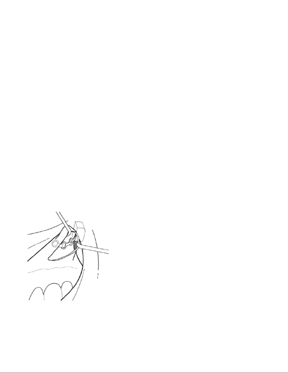
G. Attach the Microstimulator
Use the Bone Fixation Plate and at least two 1.8 mm craniomaxillofacial bone screws (not
provided by Autonomic Technologies) to anchor the Microstimulator to the anterior zygomatic
process of the maxilla, which contains thick, dense bone (Figure 16). Care should be taken to
confirm that the distal lead has not entered the inferior orbital fissure or nasal cavity.
NOTE: The Microstimulator should be placed such that the flat portion of the Microstimulator
Body and Bone Fixation Plate are facing the maxillary bone.
NOTE: Confirm the Microstimulator’s distal lead position using fluoroscopy or X-ray.
NOTE: Fix the Microstimulator to thick, dense bone to avoid potential dislodgement.
NOTE: Take care to avoid displacement of the Microstimulator while bending the Bone
Fixation Plate.
NOTE: The Bone Fixation Plate can also accept a rescue screw, if needed, of up to 1.8 mm in
diameter.
NOTE: Implant the microstimulator at least 1.2cm from the skin surface to ensure the ability to
use all available power setting during therapy.
Figure 16: Anchoring the Microstimulator
H. Intra-Operative Functionality Testing
To confirm proper Microstimulator functionality, perform an implant impedance test. To do so,
hold the sterile-sleeved Remote Controller to the Patient’s cheek above the implant or instruct
a Scrub Tech to do so. Next, use the Programming Software to wirelessly connect the Remote
Controller to the Microstimulator (or instruct a Scrub Tech to do so). Select the impedance test

20
option in the Programming Software. If the Programming Software confirms that the
impedance test is successful, then the procedure may proceed. If the test is not successful,
then select a higher implant depth and repeat the test. If the Microstimulator does not respond
to repeated testing, then a new Mircrostimulator must be used. Refer to the Pulsante®
Programming Manual for information on proper use of the Programmer Software and Remote
Controller.
NOTE: If you encounter any issues during intra-operative testing, refer to the Troubleshooting
Section of the Pulsante® Programming Manual for further guidance.
I. Surgical Closure
Close the incision using standard oral surgery techniques. Should a clinician decide to remove
the Microstimulator in the future, it can be removed using standard procedures to open the
incision and remove the bone screws from the Microstimulator Bone Fixation Plate.
J. Post-Operative Care
Observe all standard oral post-operative standard-of-care procedures.
12. DISPOSAL
Remote Controller
Please send any non-functional Remote Controllers to Autonomic Technologies for analysis (ATI
contact information is provided at the back of this manual). Do not throw away the Remote Controller
in the trash.
Microstimulator
In the event that an Microstimulator is explanted, please return the device to Autonomic Technologies
for analysis. Do not throw away the Microstimulator in the trash.
Surgical Tools
The Surgical Tools are intended for single use only. After use, please dispose of the Surgical Tools
using standard Operating Room disposal procedures.
Table of contents
Popular Medical Equipment manuals by other brands


Getinge
Getinge Arjohuntleigh Nimbus 3 Professional Instructions for use

Mettler Electronics
Mettler Electronics Sonicator 730 Maintenance manual

Pressalit Care
Pressalit Care R1100 Mounting instruction

Denas MS
Denas MS DENAS-T operating manual

bort medical
bort medical ActiveColor quick guide

AccuVein
AccuVein AV400 user manual


