Autoslide iLock User manual

1hh
WELCOME
Congratulations on the purchase of your new AutoSlide automatic door
opening system. Please carefully read through these instructions before
beginning the installation. This manual is designed for the installation of the
AutoSlide Standard, Standard iLock, Elite, and Elite iLock systems onto a single
sliding panel door.
We hope AutoSlide improves the quality of your life by providing easy access
and convenience throughout your home.
Hi,
I’m an IT specialist from Autoslide North America. I‘ve installed
thousands of AutoSlide units on all types of sliding doors in
many different situations.
We’ve included all the parts you’ll need to automate your door
and listed the tools required for easy installation. If you run into
any problems, please email us at: [email protected].
For faster technical support, visit us online at
www.autoslide.com/support
We are here to help you.
- Team Autoslide

CONTENT

3hh
IN YOUR BOX
AUTOSLIDE DRIVE SYSTEM
Contains the motor and electronic controller
that allows you to calibrate and control the
door opening. A metal cover protects and
conceals the AutoSlide’s electronic
components.
L-MOUNTING ADAPTER BRACKET
Metal bracket used to create a head
mount above the door when one is not
present. Bracket is adjustable using
sliding holes for screws.
FRICTION TESTER
Used to test your door’s drag
force. Does not apply to Elite and
Elite iLocking AutoSlides.
POWER PACK
Converts AC power source to
24 volts DC for AutoSlide
system.
Standard Power Pack (top),
Elite Power Pack (right)

IN YOUR BOX
SCREWS AND TOOLS
Use the included screws to mount the
AutoSlide drive unit. The small flathead
screwdriver is used to adjust the DIP
switch positions, and the Allen key may
be used to re-hand the drive unit if
needed. Note that additional screws may
be needed depending on your door.
RACK
The track mounted to your active
sliding door panel. The motor gear
uses the rack to push and pull your
door open and closed. Each track is
20” long, and two are included with
every kit.
RACK SCREWS
Use these screws and endcaps to attach the
rack to your active sliding panel.
WALL PUSH BUTTONS
Used to activate the AutoSlide system to open
and close the door. These buttons connect
wirelessly. Two are included with every system.

5hh
WHAT YOU’LL NEED
SCREWDRIVER
A No. 2 flat head
screwdriver and
Phillips head
screwdriver are
recommended.
DRILL
The unit and tracks
will need to be drill
mounted to the door.
An assortment of drill
bits is recommended.
HACK SAW
Needed to cut off
any excess rack
once sized to the
sliding panel width.
TAPE MEASURE & MARKING PENCIL
Needed for
marking and
measuring drill
holes, rack
lengths.
MOUNTING MEDIUM RECOMMENDED FIXING METHOD
DRYWALL
DRYWALL ANCHORS
MASONRY CONCRETE ANCHORS
TAPCONS
VINYL, WOOD NORMAL SCREWS
SELF
-
TAPPER
S
METAL
DRILL PILOT HOLE &
SELF
-
TAPPERS
Depending on the door and mounting options, additional materials may be needed to
attach the system to the door. This may include shims to extend out the rack or move
the unit down, drywall anchors or concrete anchors, specialized screws, etc. For
mounting assistance, please contact Autoslide support staff directly with pictures of the
door and frame.

STAGES OF A STANDARD INSTALL INCLUDE…
Approximately
90 minutes
INSTALL
During the install, you will mount the AutoSlide
drive system to the door frame or floor, then attach
the rack to the sliding door panel.
PREPARE
To prepare for the install, you will need to
assess the scenario: check the door's readiness,
test the drag force of the door, plan how the
system will mount, and gather any necessary
tools and materials.
OPERATE
To operate your door, you will need to connect the
power and program the Controller. Once
connected, you can then synchronize the Wall
Push Buttons and/or other sensors to the Controller
and test how the door operates.
FINALIZE
Once installed and set up, place the cover back on
the drive unit and conceal cables as desired. The
unit can also be concealed and covered with a
faux valence or access panel.

7hh
BEFORE YOU BEGIN
You will need a power point (outlet)
near your door to plug in your
AutoSlide unit. Confirm a power
point is near the installation position
and can be reached by the included
power cable. Otherwise, a heavy
duty extension cable or AutoSlide
extension cable can be used.
Note: If necessary, contact a
professional electrician to install a
new outlet or electric cabling.
WORKING ORDER
Assess the operating condition of your door before installing the
AutoSlide. Check the door:
Rolls smoothly and is level. The best way to check if the
door is level is by closing the door, leaving a finger size
gap between door and jamb. Run your finger along the
gap to see if it is even from top to bottom.
Track is clean and is free of foreign objects. If
necessary, use a silicone or aluminum based lubricant
to reduce resistance.
Note: If the door is not sliding smoothly or level, contact a
local professional to perform maintenance.
Close door completely
Check if edge of door isn’t
parallel with edge of jamb

THE FRICTION TEST
If the Velcro…
Then…
Stays intact Your door is ready for the
AutoSlide system to be installed.
Go to the next page.
Breaks during
the test
Your door is not yet ready for the
AutoSlide to be installed. You
may need to improve the sliding
action with some maintenance.
Note: If the door is in good
working order but is too heavy,
you must upgrade to an Elite
Motor.
Contact Autoslide about
upgrading at (833) 337-5433.
A simple friction test is used to confirm the drag
force of your door. This will determine if the
Standard Motor or the Elite Motor is needed to
open and close your door. Your sliding door must
be in proper working condition and run freely
along its track.
1. Close the door.
2. Wrap/loop the friction tester
around the sliding door handle
and secure the Velcro.
3. Pull on the Friction Tester with even force
to fully open and close the door 3 times.
Use the same force as you would to
normally open the door and assess.
Standard Motors
will have a
silver
barrel
Elite Motors will have a black barrel
The test strip is only
used on Standard
units. If you already
have an Elite unit,
this test can be
skipped.

9hh
DRIVE MOUNTING OPTIONS - TOP
The drive system's preferred mounting location
is to the head above the door. The unit may be
mounted inside or outside and is determined by
the track of the active panel (i.e. active panel on
inside track requires mounting inside the home).
When possible, an inside mount is the preferred
location.
TOP MOUNT OVER FIXED PANEL
This is the preferred mounting option when the
sliding panel opens to the left when viewed on
the side of the active panel (as shown).
If the system must be mounted over the fixed panel (for
clearance/aesthetic purposes) and the door opens to the
right, it is necessary to rehand the unit (see Section 07
prior to installing).
ADAPTER BRACKET
If the door header doesn’t have enough depth to
mount the unit onto it, you can use the included
mounting adapter "L" bracket to facilitate a
mount directly to the wall. The bracket can be
used in a variety of ways, including as
reinforcement.
In some situations, it may be necessary to drill new holes
into the unit base. If so, take great care to not damage
any hardware or cables.
VERTICAL GAP
If the motor wheel can’t vertically meet the track
(and the track is placed as high as possible), use
a block of wood or metal to shim the unit down
closer to the track. It will likely be necessary to
mark and pre-drill your holes in the shim.
SLIDING
PANEL
SLIDING
PANEL
WALL
DOOR
ADAPTER
BRACKET
Top Mount Over Active Panel
Top Mount Over Fixed Panel
Inside vs. Outside Mount

DRIVE MOUNTING OPTIONS - BOTTOM
BOTTOM MOUNT UNDER FIXED
PANEL
LEFT-HANDED
DOOR
If the drive system cannot be mounted at
the top of the door frame, it can be
mounted to the floor. Floor mounting
should be used as a final option only, if
top mounting isn’t possible. Use this
example if your door opens lef to right.
BOTTOM MOUNT UNDER FIXED
PANEL
RIGHT-HANDED
DOOR
If the door opens from right to left, floor
mounting the unit in its default
configuration will cause it to extend into the
door opening; in this case, the unit must
be re-handed (see below) so the unit body
stays under the fixed panel.
REHANDING
If floor mounting on a right-handed door, it is
required to re-hand the system (reversing the
position of the motor and control panel). Refer
to Section 07 to rehand before installing.
VERTICAL GAP
If the motor wheel can’t vertically meet the
track (and the track is as low as possible),
use a block of wood or metal to shim the unit
up closer to the track. It will likely be
necessary to mark and predrill your holes in
the shim.
SLIDING
PANEL
Often clearance can be an issue when
installing tracks for a floor-mounted system.
Note that the tracks can be installed flange
up or flange down to avoid drilling into the
glass
(see figures to the right)
.
SLIDING
PANEL

11hh
TRACK TYPES AND CHANNEL SIZE
The AutoSlide kit by default includes regular tracks (shown below on the left). Slimline tracks
(right) are available upon request before purchasing and are designed for barn and pocket doors.
LIMITED DOOR FRAME
If the top frame of the sliding
panel is too thin, you can
mount a metal bar to
the sides of the sliding panel.
Then mount the tracks to
the bar. The bar should span
the full width of the sliding panel.
If there isn’t enough frame on the door's sides
to bar mount the tracks, they can also be
secured to the door using 3M VHB industrial
tape. Contact a specialist on the recommended
tape for your door material. If adhering to glass,
seal the glass first to prevent moisture weeping
into tape.
HORIZONTAL GAP
If the tracks
don’t meet the
motor wheel
due to a
horizontal gap,
use spacers or
shims to extend
out the track.
Alternatively, motor wheels with longer pinions
are available on request when purchasing. The
longer pinion will extend the wheel up to 1”.
TRACK MOUNTING OPTIONS
Once the drive system is mounted, the tracks can be securely mounted, using a drill, to the
sliding door panel engaging the motor wheel. The tracks can be mounted flange up or flange
down depending on clearance.
FLANGE
DOWN
FLANGE
UP

DRIVE MOUNTING
This section will show the top mount installation process onto a right-handed door. Please note the exact
process may vary; refer to the previous section to prepare your door prior to starting installation.
Mount the drive system to the door's
header using the three holes on the
back of system base like shown.
oAllow for 3” / 75mm overlap of the AutoSlide unit
and the back of the sliding panel when the door is
fully closed.
As a guideline, the center of the motor wheel should be
1⅜“ / 35mm from the back edge of the sliding panel
(regardless of mounting placement or door orientation).
oEnsure the motor wheel will remain within the edges
of the sliding panel when fully opened/closed. If the
motor wheel goes past the sliding panel’s front edge
when opened fully, the overlap described above can
be reduced to 2⅜” / 60mm (but track endcaps
cannot be used in Step 2).
oThe inset edge of the unit endcap (see diagram to right) should be 21mm to
25mm from the sliding panel’s surface (plus the width of any shim that will be
used with the tracks).
If the system is mounted as close as possible and this
measurement exceeds 25mm, the tracks must be shimmed out as
depicted to the right (or a longer motor wheel pinion used).
1)
SLIDING PANEL
(closed)
FIXED PANEL 3”
75mm
SLIDING PANEL
(open)
Ensure the motor wheel stays
within the edges of the sliding
panel even when fully open.
Otherwise, reduce 3” overlap.
21
–
25 mm
21–25 mm
SLIDING
PANEL
Bottom view, primary mounting holes circled in red

13hh
DRIVE MOUNTING
oThe bottom of the motor wheel should reach
below the bottom edge of the door frame, so that
the motor wheel can meet the track once
mounted.
oIf the motor wheel doesn’t reach below the
edge of the door frame, there will be a vertical
gap between the wheel and track. In this case,
the unit will need to be shimmed down.
Note: If the top header doesn’t have enough width to
mount the system, the adapter bracket can facilitate a
direct wall mount (as shown). Note the unit can be
adjusted both vertically and horizontally with the bracket.
This adapter bracket can also be used as reinforcement,
and can be mounted either flange up or flange down.
Door frame
Motor wheel
must reach below
door frame
SLIDING
PANEL
1)
WALL
SLIDING
PANEL
ADAPTER
BRACKET
Mounting adapter
(green)
used
flange up, drill mounted to wall
ADAPTER
BRACKET
Mounting adapter (green) used flange
down, drill mounted to door frame; do not
drill into the rail for the sliding panel itself

TRACK CUTTING
2) a) Join the tracks together
using the grooves at the
ends.
b) Fully close the door into the jamb.
Measure the exposed width of the
sliding panel (from the back edge
of the sliding panel to the start of
the jamb). Use a hacksaw to
cut the tracks to match this width.
Note: If the location of the cut is not near a
mounting hole on the track, you can either drill a
new hole into the track or use one of the optional
track endcaps for support. Four additional teeth
may need to be cut from the track for each
endcap. If using track endcaps, ensure the motor
wheel does not hit an endcap (whether fully open
or fully closed) once the tracks are mounted.
Note: If the total track length is shorter than the
sliding panel width, the AutoSlide will still be able
to automatically open the door partially. In this
case, a door stopper should be installed to
prevent the sliding panel from opening too far and
running off the AutoSlide track.
SLIDING PANEL
(fully closed into jamb)

15hh
TRACK MOUNTING
3)
a) Hold the track to the sliding door
panel (closed). Align the edge of the
track with the back (non-leading)
edge of the door as shown.
Note: The tracks can be mounted flange up (see
below) or flange down (see below right). Take great
care to note how far your glass goes into your panel
frame, and mount accordingly to avoid drilling into the
glass.
b) Keeping the track in place relative
to the sliding panel, open the door
to the first position where a track
mounting hole is accessible and
close to the motor wheel.
c) While holding the track up
tightly to the motor wheel,
drill in the first screw.
If the tracks aren’t installed with
enough pressure on the motor wheel,
the motor wheel may grind against the
track during setup or use.
FLANGE
DOWN
FLANGE
UP
Align track with back
edge of door panel
Hole should be as close as possible to
motor wheel while being accessible

TRACK MOUNTING
3) d) Once secure, slide the door so that the next track mounting hole is close
to the motor wheel. While pushing upwards on the track to the motor
wheel, drill in the next screw.
e) Repeat for remaining mounting holes until track is entirely mounted to
sliding panel. Be sure to firmly hold the track up to the motor wheel each
time.
f) Once the track is attached to the door, open and close the door manually
to ensure the door runs smoothly without any interference. Ensure the
motor wheel is consistently engaging with the track in all positions.
Ensure the track is mounted to the
sliding panel at every available hole,
especially at the ends

17hh
LOCKING, MODE, AND SENSOR PORT GUIDE
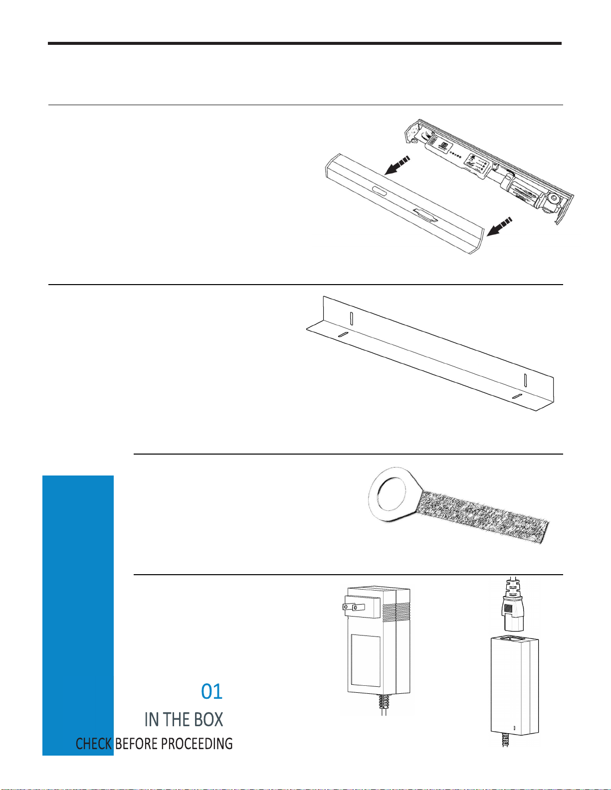
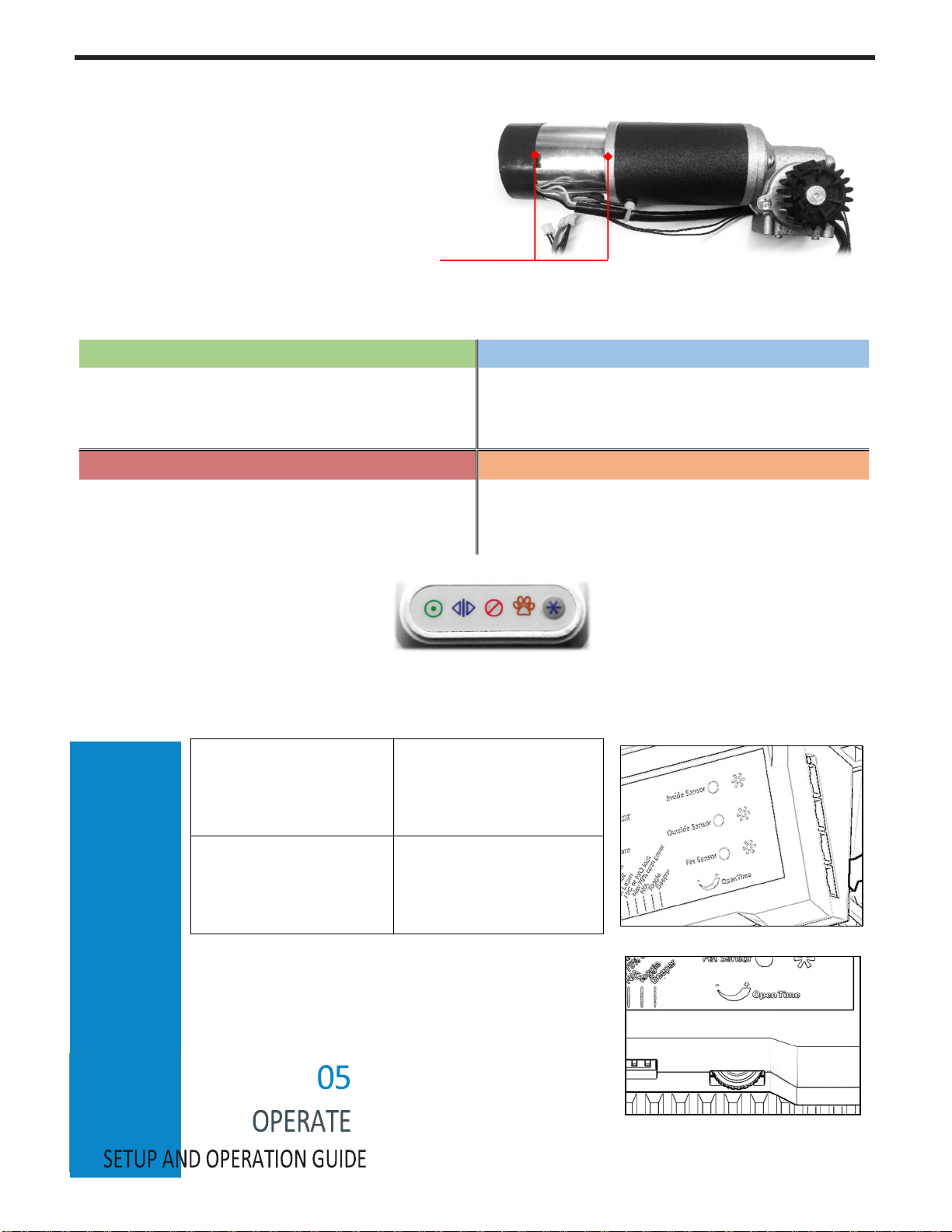
The AutoSlide Standard iLock and Autoslide Elite
iLock include a dynamic breaking lock built into the
motor. This will lock the door when closed, provided
the AutoSlide is in a locking mode. An iLock system
will always include a chrome cylindrical segment
towards the end of the motor barrel:
The AutoSlide system uses four unique modes:
Green
/ Auto Mode
Blue
/ Stacker Mode
A mode for everyday human use. Pet sensors
are disabled, open-assist is enabled, and the
door doesn’t lock. Most commonly used mode.
By default, keeps the door fully open. A sensor
connected to the Stacker Port can operate the
door like a garage door, leaving it open partially.
Red
/ Secure Mode
Orange
/ Pet Mode
A security mode designed for use with iLock
units. Outside sensors are disabled, open-
assist is disabled, and the door is locked.
Primary mode for pet use. Pet and Inside
sensors are enabled. Outside sensors can be
disabled. Pet distance enabled. Door is locked.
These are indicated by the four mode
icons on the front of the control panel:
There are four sensor ports located on the right side of the control panel:
Inside Sensor (top port):
A master channel enabled in
Green, Red, and Pet Mode.
Opens to the programmed full
width.
Outside Sensor (2nd port
down): A secondary channel
enabled in Green and Pet (if
desired) Mode. Opens to
programmed full width.
Pet Sensor (3rd port
down): A special channel
enabled in Pet Mode only.
Opens to the programmed
partial pet width.
Stacker Sensor (bottom
port): A specialized channel
enabled in Blue Mode only.
Can be used to keep the door
open partially if desired.
The Open Time dial is located at the bottom of the control panel
and keeps the door open between 0-24 seconds before closing. If
the dial is turned to the max, the system enters into Toggle Mode,
The door then operates per activation of sensor, push to open
and push to close. This can be used in Green and Red Modes.
The desired mode is selected by
successive presses of the Mode button (to
the right of the mode icons). The modes will
cycle in the order displayed, though Pet
Mode will be skipped if not programmed.
Elite iLocking Motor

DIP SWITCH SETTINGS GUIDE
Eight white DIP switches are located at the bottom of the control panel:
1
Direction/Learn
Leave in OFF position for right-handed door
operation. Leave in ON position for left-
handed door operation.
Toggling this back & forth in Blue Mode will
program the stacker opening width.
Toggling this back & forth in green or red
mode programs the human opening width.
2
Slam Shut
Boosts power at the start of the opening
and end of the closing of the door when
in ON position.
Designed for tight jambs and
weatherseals.
Can’t be used when DIP #7 is
ON.
3
Pet Learn
This switch is used to program the pet width
of the AutoSlide.
Toggle ON and OFF to start and stop the
door at the desired pet open width.
The direction (left-opening vs right-opening)
is already determined from DIP #1.
4
Secure Pet
This switch is used to disable the Outside
Sensor channel in Pet Mode.
Designed for security-based pet setups
with iLock units.
5
75% Power
Reduces the power of the motor if the unit
opens too fast or if the door is too light in
weight.
Usually turned ON when automating
lightweight screen doors or pocket doors.
6
App Control
When turned OFF, enables manual
motherboard control of the system.
When turned ON, enables Bluetooth
Module (app) control of the system.
This should only be on if an Bluetooth
module is plugged in and installed.
7
Extra Power
Increases the amount of power the motor
uses for heavier sliding doors.
Turn ON if motor is struggling to open/close
door.
This cannot be used when DIP #2 is ON.
8
Beep
When turned ON, the AutoSlide will emit
an audible beep when the door opens,
starts to close, and when it changes
modes.
OFF position is towards the
front of the control panel
ON position is towards
the back of the control
panel

19hh
POWERING ON AND INITIALIZING
1) Ensure the red power switch on the side of
the control panel is set to OFF (O down).
Configure DIP switch settings as desired.
Ensure DIP switch #1 is flipped OFF
(towards the front of the unit’s control
panel).
Plug the included power pack into the
AutoSlide system’s power port (located on
the unit's left endcap). Plug the other end
into the closest available wall outlet.
This manual suits for next models
2
Table of contents
Other Autoslide Door Opening System manuals
Popular Door Opening System manuals by other brands

Command access
Command access PD10-M-RIM installation instructions

Schulte
Schulte FSA ECO SR-EFR BG Assembly instructions

RADEMACHER
RADEMACHER RolloSystems T2 instruction manual

MTH
MTH PLCE Use and maintenance manual

Norton
Norton tri-style 1603BC installation instructions

LockMaster
LockMaster LOCKONE LKM10K operating instructions