Autoslide MultiDrive User manual

MultiDriveTM
Installation instructions

© 2018 Autoslide Pty Ltd 2
Contents
The MultiDrive 3
Repairs and returns 3
Questions and comments 3
Warranty 3
About the MultiDrive 5
What’s included 6
Door requirements 8
Sliding door friction 8
Space under the transom 8
Coating the cover 9
Installation instructions 10
1. Cut parts to size 10
2. Attach parts to the base 12
3. Attach the base to the door 22
4. Attach the brackets and cover 24
5. Install the mode pad 27
Programming the controller 30
1. Learn wireless inputs 30
2. Set DIP switches 31
3. Set the controller for pets 32
4. MultiDrive mode settings 32

© 2018 Autoslide Pty Ltd MultiDrive 3
The MultiDrive
This document explains how to assemble the MultiDrive automatic door opening
system. It is important to follow these instructions closely.
Repairs and returns
Contact us by either:
Email: [email protected]
Web: www.autoslide.com
Phone:
–(833) 337-5433 (USA)
–1 300 288 675 (Australia)
Questions and comments
If you have questions about installation, programming, or operation
of your MultiDrive or about any parts or accessories, email us at
Warranty
The MultiDrive is produced by Autoslide Pty Limited and is subject
to the following warranty and conditions of operation. The product
is warranted against failure due to faulty material or workmanship
for a period of 24 months from date of purchase. This warranty will
cover the repair or replacement of any defective parts at an
authorized Autoslide Pty Limited facility and is subject to the
following conditions, provided that:
•the MultiDrive is fitted to a sliding door strictly following the
supplied instructions, and
•the sliding door slides within the friction limits specified in the
instructions, and
•the MultiDrive is for residential and light traffic commercial
applications (ie. doctor’s office, hotel room, etc.), and
•the warranty is limited to an amount totaling no more than the
unit cost price.
This warranty shall be null and void and to no effect if:
•the MultiDrive is abused or in any way used outside the limits
of the specification and design, or
•the electric wiring has been interfered with and is not wired in
accordance with the original factory settings, or
•defects are not caused by normal wear and tear, or
•the purchaser in any way alters the MultiDrive, or adds or
removes parts or materials of the MultiDrive, or

© 2018 Autoslide Pty Ltd MultiDrive 4
•the purchaser fails to notify Autoslide Pty Limited immediately
if there is a failure of any component.
Conditions:
•Delivery costs of all warranty items will be covered by
Autoslide Pty Limited for the first 90 days from purchase. After
90 days, delivery costs of warranty items will be at the
purchaser’s expense.
•The purchaser will be responsible for inspecting the MultiDrive
package to ensure that the package is complete and not
damaged and that all parts are present.
•The buyer shall immediately notify Autoslide Pty Limited in
writing or by phone about any defect in the goods.
•In the event a MultiDrive unit is returned to Autoslide Pty
Limited for a warranty claim, the MultiDrive unit must be
received free from damage.
•The purchaser expressly acknowledges and agrees that
Autoslide Pty Limited is not liable for any advice given by its
agents in relation to the suitability of the product or its
application to certain doors and such advice is relied upon at
the purchaser’s risk.
•The buyer shall not carry out any remedial work on the alleged
defective goods without first obtaining the written consent and
instruction from Autoslide Pty Limited.
•The warranty on any battery is subject to the warranty provided
by the original manufacturer of the battery. Two year
© 2018 Autoslide Pty Ltd MultiDrive 5
About the MultiDrive
The MultiDrive is an automatic door opening system for
residential and light-use commercial sliding doors.
Once installed, the MultiDrive mechanism is hidden discretely
behind an aluminum cover which blends in with the sliding door
frame. This cover comes in a mill finish and will need to be powder
coated to match the door and/or frame.
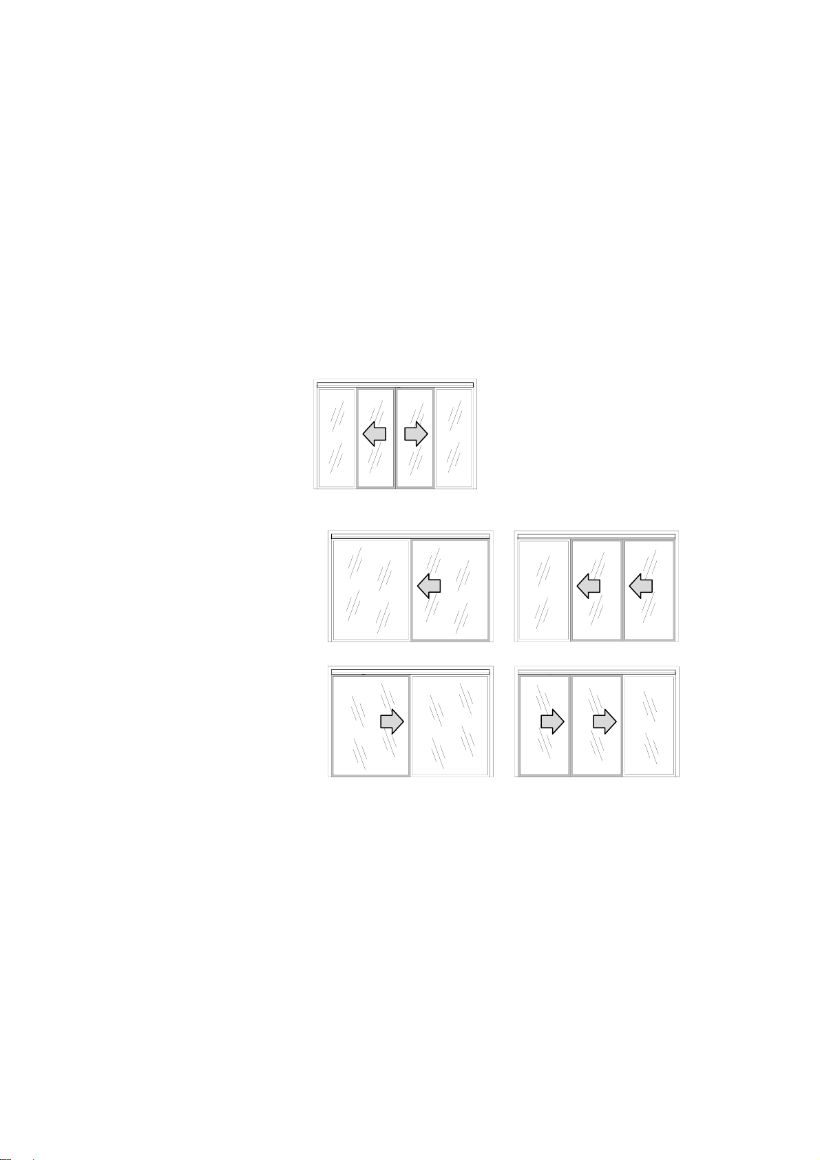
The MultiDrive can be retro-fitted to any framed sliding door,
including bi-parting doors (Figure 1) and non-bi-parting doors
(Figure 2).
Figure 1: Bi-parting doors with the MultiDrive.
a) b)
c) d)
Figure 2: Non-bi-parting doors with the MultiDrive: a) single left-
sliding door, b) telescopic left-sliding door, c) single right-sliding
door, and d) telescopic right-sliding door.
Warnings
•Any manual lock on the sliding door should be removed or
deactivated, otherwise the MultiDrive may be damaged if
activated while the lock is closed.
•The MultiDrive should not be used in high-traffic
environments such as large office building entrances or big-
box stores.
•The MultiDrive may be used in light commercial
environments. Speak with an authorized Autoslide Pty
representative about your application prior to purchase.

© 2018 Autoslide Pty Ltd MultiDrive 6
What’s included
Base
x 1
Cover
x 1
AC adapter
x 1
Controller
x 1
Motor
x 1
Belt
x 1
Top bracket
x 1
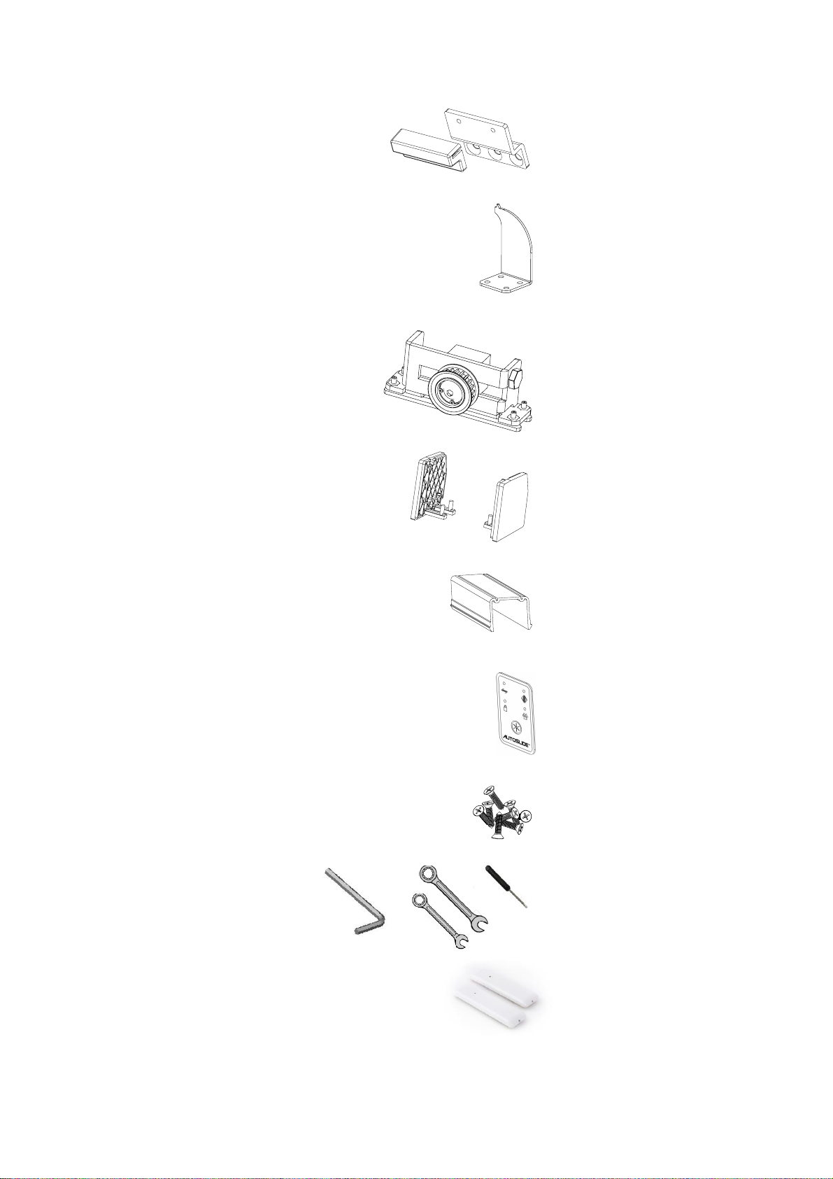
© 2018 Autoslide Pty Ltd MultiDrive 7
Bottom
bracket
x 1
Cover clip
x 2
Belt
tensioner
x 1
End cap
x 2
Cable cover
x 3
Mode pad
x 1
Screw
Packet
x 1
Tool Packet
x 1
Wall Button
X 2
© 2018 Autoslide Pty Ltd MultiDrive 8
Door requirements
Sliding door friction
The MultiDrive should only be installed on a door that slides
smoothly. If the door system does not, it is recommended to have
the door system maintenance prior to the installation of the
MultiDrive System.
The sliding friction should be low enough that the door opens and
closes with a force less than 35 pound-force plus (155 newtons)
at a steady sliding speed of about 4”/second (100 mm/second).
Use a digital scale with a hook to measure the force to open and
close the door. If the force is greater than 35 pound-force, speak
with an authorized Autoslide Pty representative on how to proceed.
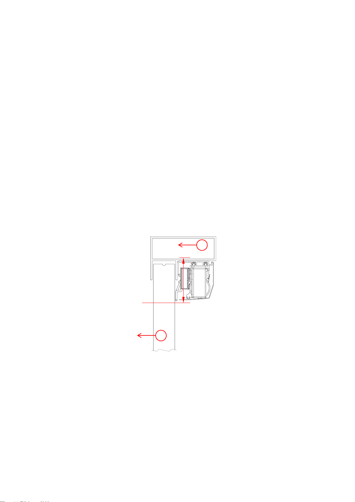
Space under the transom
The MultiDrive system sits directly below the head space of a
sliding door and requires a vertical space of 3.15”(80 mm) –see
Figure 3.
The MultiDrive may also be mounted in a flush mount, if the
situation arises.
Figure 3: Cross-section of a sliding door (1) with the MultiDrive below
the transom (2). The MultiDrive requires a 3.15-inch (80-mm)
clearance below the transom.
1
2
3.15”
(80 mm)

© 2018 Autoslide Pty Ltd MultiDrive 9
Coating the cover
The MultiDrive includes a cover to conceal the motor and other
mechanisms.
The cover has an uncoated aluminum mill finish. To make the
cover match the sliding door, use a color sample from the door
and/or door trim to match the cover with the door system. The
painting of the cover should be powder coated for optimal durability
and finish.
Leave spare material to hold the ends of the cover during the
coating process.

© 2018 Autoslide Pty Ltd MultiDrive 10
Installation instructions
1. Cut parts to size
(a) Check the MultiDrive fits
a) b)
Figure 4 Examples of a) sufficient space for the Multidrive, b)
insufficient space.
Is there a 3.15-inch (80-mm) space below the transom?
•If yes, the MultiDive should fit. Go to the next step (b).
•If no, see below.
Steps
a) b)
Figure 5: .
3.15”
80 mm
✓
3.15”
80 mm
3.15”
(80 mm)
< 0.08”
(< 2 mm)

© 2018 Autoslide Pty Ltd MultiDrive 11
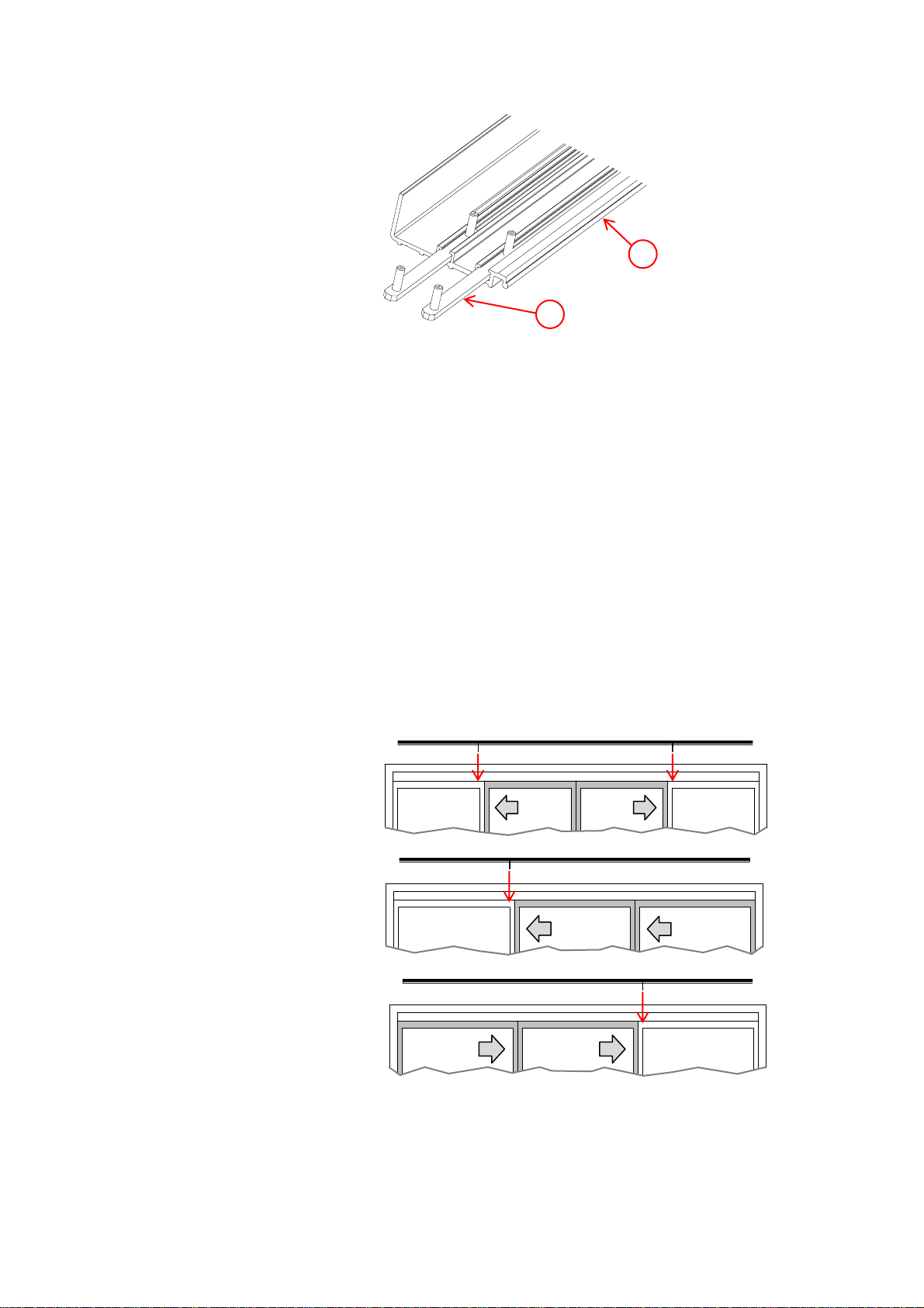
(b) Cut the cover to the correct length
Steps
Cut the cover to a length (L) which is 0.51”to 0.59”(13 to 15 mm)
shorter than the inside width (W) of the sliding door frame (see
Figure 5).
Cut off any pins or clips used to hold the cover during the coating
process.
Figure 6: Cut the cover (shown in grey) to a length Lwhich is 0.51”to
0.59” (13-15 mm) shorter than W.
(c) Cut the base to the same length
Cut the base to the same length Las the cover (0.51”to 0.59”or
13 to 15 mm shorter than W).
W
L

© 2018 Autoslide Pty Ltd MultiDrive 12
2. Attach Parts to the Base Prior to Mounting
The base holds the belt tensioner, motor, controller, AC adapter,
cover clips, Wi-Fi Module, and back up battery (option accessory).
It is important to place these parts in the correct positions
described below.
(a) Preparation
The layout of parts depends on whether the door is bi-parting, right
handed, or left handed.
Figure 7: Bi-parting doors: motor (1) is on the left.
Figure 8: Right handed door: motor (1) is on the left.
Figure 9: Left handed door: motor (1) is on the right.
Steps
1. Lay the base on the floor directly in front of the door frame.
Align the center of the base with the center of the door frame.
2. Each part attaches to the base with one or two “sliders”
(Figure 10), which fit into the tracks on the base. Remove the
nuts from all sliders.
3. If you are installing optional wired sensors, lay the sensor
cable(s) on the base between the two tracks. The sensor
cable(s) will pass underneath the cover clips and motor.
1
1
1
© 2018 Autoslide Pty Ltd MultiDrive 13
Figure 10: Sliders (1) in the two tracks on the base (2).
4. Use the following steps to set the position of each part on the
base.
(a) Cover clips
Guidelines for using cover clips
•Don’t use cover clips over the door opening because they will
be visible from the opposite side of some doors.
•Clips are not needed at the ends of the base because the end
caps support the cover there.
Steps
1. Use a cover clip behind the door frame of each fixed (non-
sliding) door (Figure 11). The door frame of the fixed door
hides the clip from view on the other side of the door.
Slide each cover clip onto the base as in Figure 11. Make sure
the other end of each cover clip (without sliders) points
towards the door.
Figure 11: Place a cover clip behind the door frame of each fixed
door.
DETAIL
H
SCALE
2 : 1
1
2

© 2018 Autoslide Pty Ltd MultiDrive 14
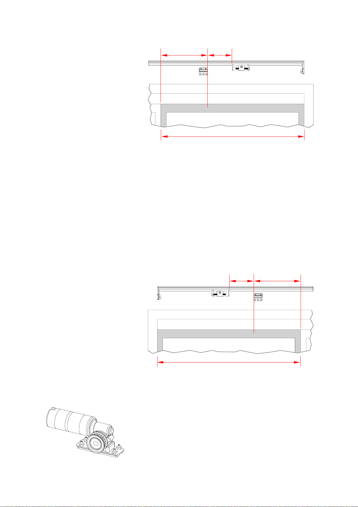
(d) Belt tensioner
For bi-parting doors:
For bi-parting doors, the belt tensioner sits on the right side of the
door frame (viewed from the inside of the door).
1. Open the doors fully.
2. Slide the belt tensioner along the base until it is in front of the
left-hand door as shown in Figure 12, where:
A= 20-30% of the width Bof that door
C = 1.97” (50 mm).
3. Tighten the slider nuts to hold the belt tensioner in place.
4. Mark the position of the bottom bracket on both the base and
the door as in Figure 12.
Figure 12: Bi-parting doors: belt tensioner and bottom bracket.
The right side is shown with the right door open.
For right handed doors (non-bi-parting):
For left-opening doors, the belt tensioner sits on the right side of
the door frame (viewed from the inside of the door).
1. Close the door fully.
2. Slide the belt tensioner along the base until it is in front of
closed sliding door as shown in Figure 13, where:
A= 20-30% of the width Bof that door
C = 1.97” (50 mm).
3. Tighten the slider nuts to hold the belt tensioner in place.
4. Mark the position of the bottom bracket on both the base and
the door as in Figure 13.
A
C
B
© 2018 Autoslide Pty Ltd MultiDrive 15
Figure 13: Left-opening sliding door: belt tensioner and bottom
bracket. The right side is shown with sliding door closed.
For left handed doors (non-bi-parting):
For right-opening doors, the belt tensioner sits on the left side of
the door frame (viewed from the inside of the door).
1. Close the door fully.
2. Slide the belt tensioner along the base until it is in front of
closed sliding door as shown in Figure 14, where:
A= 20-30% of the width Bof that door
C = 1.97” (50 mm).
3. Tighten the slider nuts to hold the belt tensioner in place.
4. Mark the position of the bottom bracket on both the base and
the door as in Figure 14.
Figure 14: Right-opening sliding door: belt tensioner and bottom
bracket. The left side is shown with sliding door closed.
(e) Motor
The motor sits at the opposite end of the base to the belt tensioner.
For bi-parting doors:
Bi-parting doors use a top bracket (unlike other types of doors).
1. Open the doors fully.
A
C
B
A
C
B
© 2018 Autoslide Pty Ltd MultiDrive 16
2. Slide the motor along the base until it is in front of left-hand
sliding door as shown in Figure 15, where:
A= 20-30% of the width Bof that door
C = 1.97” (50 mm).
Note: If the top bracket does not fit in this position (Figure 15),
contact your MultiDrive supplier about obtaining a different
style of bracket that fits onto the right edge of the door.
3. Tighten the slider nuts to hold the motor in place.
4. Mark the position of the top bracket on both the base and the
left-hand sliding door as in Figure 15.
Figure 15: Bi-parting doors: motor and top bracket. The left side
is shown with left door open.
For left-opening doors (non-bi-parting):
1. Open the door fully.
2. Slide the motor along the base until it is 1.97”(50 mm) from
the mark you made on the door for the bottom bracket position
(Figure 13 and Figure 16, where C = 1.97” or 50 mm).
3. Tighten the slider nuts to hold the motor in place.
Note: Non-bi-parting doors do not use a top bracket.
Figure 16: Left-opening sliding door with motor and bottom
bracket. The left side is shown with the sliding door open.
For right-opening doors (non-bi-parting):
1. Open the door fully.
B
A
C
C

© 2018 Autoslide Pty Ltd MultiDrive 17
2. Slide the motor along the base until it is 1.97”(50 mm) from
the mark you made on the door for the bottom bracket position
(Figure 14 and Figure 17, where C = 1.97” or 50 mm).
3. Tighten the slider nuts to hold the motor in place.
Note: Non-bi-parting doors do not use a top bracket.
Figure 17: Right-opening sliding door: motor and bottom
bracket. The right side is shown with the sliding door open.
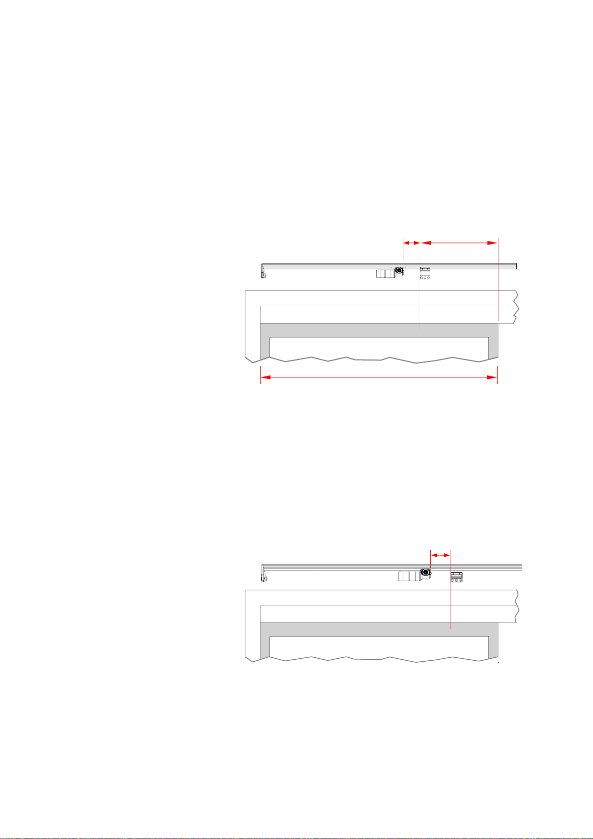
(f) Controller and AC adapter
The controller and AC adapter sit next to the motor.
Steps:
1. Lay the motor cable on the base in between the two tracks.
2. Slide the controller along the base (over the motor cable) until
it is 1.97”(50 mm) from the motor (see Figures to 18 to 20,
depending on the type of door, where D= 1.97” or 50 mm).
The slider should be in the track furthest from the door.
3. Slide the AC adapter along the base (over the motor cable)
until it is 1.97”(50 mm) from the controller (Figures to 18 to 20
where D= 1.97” or 50 mm). The slider should be in the track
furthest from the door.
4. If you are installing a mode pad on the door jamb, lay the cable
connected to the mode pad on the base between the two
tracks and underneath the AC adapter.
5. Clip the cable cover (cut it if necessary) over exposed cables
on the base to prevent cables touching the belt.
C

© 2018 Autoslide Pty Ltd MultiDrive 18
Figure 18: Bi-parting doors: AC adapter (1), controller (2), and
motor (3).
Figure 19: Right-opening door: AC adapter (1), controller (2), and
motor (3).
Figure 20: Left-opening door: AC adapter (1), controller (2), and
motor (3).
6. Tighten the slider nuts to hold the AC adapter and controller in
place.
7. Plug the motor cable into the controller (Figure 21) in a socket
labeled Motor.
8. Plug the AC adapter cable into the controller (Figure 21) in a
socket labeled Power.
3
2
1
D
D
3
1
2
1
D
D
3
2
3
1
D
D
© 2018 Autoslide Pty Ltd MultiDrive 19
Figure 21: Plug the cables into the controller.
9. Fold up any spare cable from the AC adapter and fit it between
the AC adapter and base.
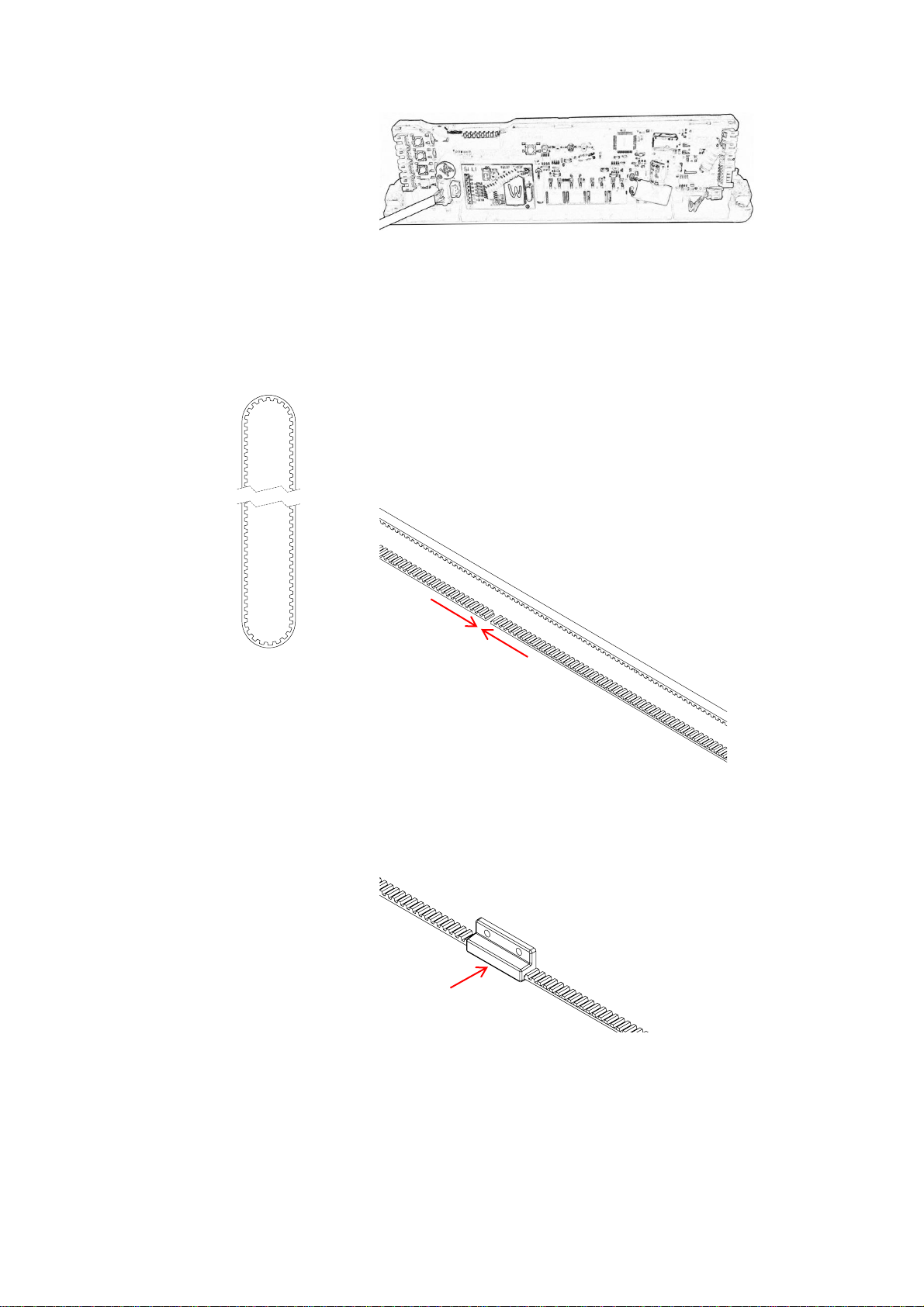
(g) Belt
Steps:
1. Take a length of belt and pass it around the motor pulley and
the belt tensioner pulley to form a loop.
One side of the loop will be closer to the base than the other
side. Keep the unjoined side furthest from the base.
2. Use your hands to gently pull the belt tight. Cut the belt so that
the two ends can touch without overlapping (Figure 22).
Figure 22: Cut the belt so that the two ends touch without
overlapping.
3. Keep two ends of the belt as close as possible to each other
and insert them into the bottom bracket (Figure 23)..
Figure 23: Insert the two ends of the belt into the bottom bracket.
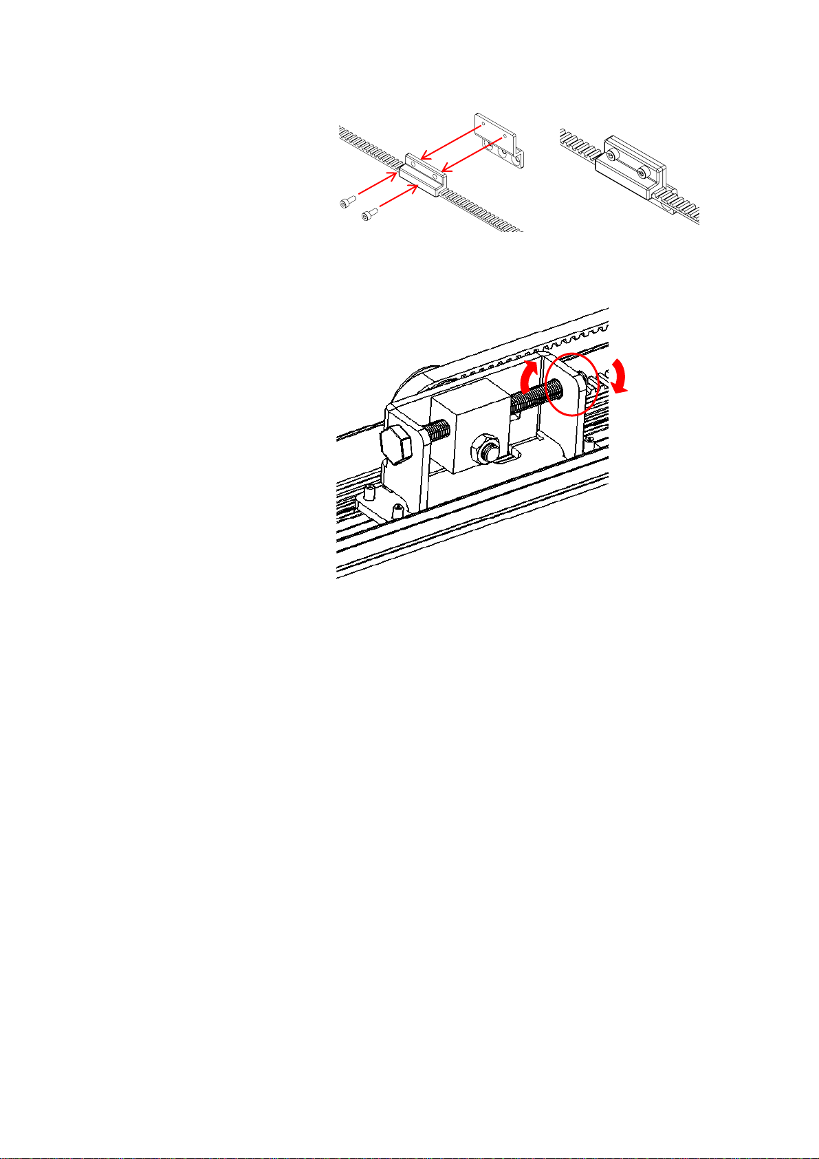
4. Bolt together the two parts of the bottom bracket (Figure 24).
E
A
C
D
B
F
G
H
DETAIL
A
SCALE
1 : 1
DETAIL
B
SCALE
1 : 1
DETAIL
C
SCALE
1 : 1
DETAIL
D
SCALE
1 : 1
DETAIL
E
SCALE
1 : 1
DETAIL
F
SCALE
1 : 1
DETAIL
G
SCALE
1 : 1
DETAIL
H
SCALE
1 : 1
E
A
C
D
B
F
G
H
DETAIL
A
SCALE
1 : 1
DETAIL
B
SCALE
1 : 1
DETAIL
C
SCALE
1 : 1
DETAIL
D
SCALE
1 : 1
DETAIL
E
SCALE
1 : 1
DETAIL
F
SCALE
1 : 1
DETAIL
G
SCALE
1 : 1
DETAIL
H
SCALE
1 : 1
© 2018 Autoslide Pty Ltd MultiDrive 20
Figure 24: Bolt together the two parts of the bottom bracket.
5. On the belt tensioner, loosen the locking nut (located on the
long tensioning bolt –see Figure 25).
Figure 25: Loosen the locking nut.
6. Turn the tensioning bolt clockwise (Figure 26) to put tension
on the belt. Stop when the belt is pulled straight and does
not sag.
Do not keep tensioning the belt after it is pulled straight
(or the motor may get damaged).
Note: If the belt loosens when the tensioning bolt is turned
clockwise, then:
–completely unscrew the tensioning bolt until it is removed
from the tensioning pulley, then
–insert the tensioning bolt into the opposite end of the
tensioning pulley (where the locking nut was previously)
and screw it into place, then
–screw the locking nut back onto the tensioning bolt.
E
A
C
D
B
F
G
H
DETAIL
A
SCALE
1 : 1
DETAIL
B
SCALE
1 : 1
DETAIL
C
SCALE
1 : 1
DETAIL
D
SCALE
1 : 1
DETAIL
E
SCALE
1 : 1
DETAIL
F
SCALE
1 : 1
DETAIL
G
SCALE
1 : 1
DETAIL
H
SCALE
1 : 1
E
A
C
D
B
F
G
H
DETAIL
A
SCALE
1 : 1
DETAIL
B
SCALE
1 : 1
DETAIL
C
SCALE
1 : 1
DETAIL
D
SCALE
1 : 1
DETAIL
E
SCALE
1 : 1
DETAIL
F
SCALE
1 : 1
DETAIL
G
SCALE
1 : 1
DETAIL
H
SCALE
1 : 1
I
DETAIL
I
SCALE
1 : 1
J
DETAIL
J
SCALE
1 : 1
K
DETAIL
K
SCALE
1 : 1
Table of contents
Other Autoslide Door Opening System manuals


Popular Door Opening System manuals by other brands


4Ddoors
4Ddoors 4DR2 Installation instructions and user guide

Lamp
Lamp FD35EV installation manual

Elvox
Elvox Sound system GIOTTO operating instructions

Cavity Sliders
Cavity Sliders SofStop installation instructions

DEUTSCHTEC
DEUTSCHTEC SLH Series installation manual

Bohle
Bohle BO 5215433 instruction manual