International Door Closers ADJUSTABLE POWER D300 Series User manual

“ADJUSTABLE POWER” Concealed Overhead Door Closer
Series D300
Center Hung\Double or Single Acting
Side and End Loading
Installation Instruction
COPYRIGHT 2016 INTERNATIONAL DOOR CLOSERS INC
East: 1920 Air Lane Drive, Nashville, TN 37210 ■615/885-7060
West: 4431 E. La Palma, Anaheim, CA 92807 ■714/666-0390
1
Patent Pending 15/296,436 & 29/581,313

“ADJUSTABLE POWER” Concealed Overhead Door Closer
Series D300
Center Hung\Double or Single Acting
Side and End Loading
HEADERS & JAMBS
COPYRIGHT 2016 INTERNATIONAL DOOR CLOSERS INC
T-30002
DOOR HEADER
Drill and counter sink outside top surface for 10-32 x
⅜” and ¼-20 x 1 ¼’ flat head screws as shown.
COVER PLATE
Drill 1 ¾“ hole as shown.
Drill ½“ hole as shown.
HINGE JAMB
Drill holes for 8-32 x ½“
pan head self-threading
screws as shown.
Install anchor using
8-32 x ½“ pan head
self-threading screws.
Mount door header on
anchor using 10-32 x ⅜”
flat head self-threading
screws/
2
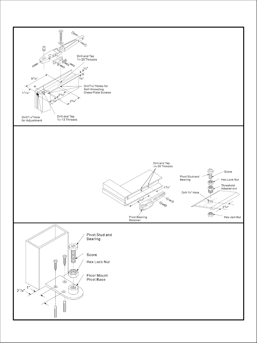
SIDE LOADING
3
COPYRIGHT 2016 INTERNATIONAL DOOR CLOSERS INC
TOP DOOR RAIL
“S” Type Side Loading Arm
Drill or drill and tap holes in top of door as shown.
Make 2 ¼“ x ½“ cut-out in top of door as shown. Cut-out must
be on the inside of the door .
Install arm using ¼-20 x 1 ¼“ flat head machine screw and ⅞”
washer. Install ½-13 x ¾” arm stud and ¼-20 x 11/8” dome
head arm adjustment screw. Laterally adjust center of the arm
spindle retainer 2 ⅝” from hinge edge of door (not including
weather stripping). Center arm in the top rail by adjusting the
two ¼-20 x 1” hex head centering bolts. After installation of
door, attach dress plate with self-threading screws.
NOTE: Before attaching dress plate, make certain the three ¼
-20 x ⅞” socket head clamp bar screws with lock washers are
tightened securely.
BOTTOM DOOR RAIL
Side Loading
Drill and tap ¼-20 holes in bottom rail of door as shown.
Install pivot bearing retainer in bottom of door using two
¼-20 x ⅝” pan head machine screws and lock washers.
Laterally adjust center of pivot bearing retainer 2 ⅝” from
hinge edge of door (not including weather stripping) and
tightened screws securely.
THRESHOLD MOUNT PIVOT
Drill hole in threshold as shown. Install threshold adapter
nut from top and secure with ¾-16 hex jam nut
underneath. Install pivot stud and bearing with ½-20 hex
lock nut as shown and adjust bearing height for proper
door clearance and firmly tighten lock nut
FLOOR MOUNT PIVOT
Center pivot base against door jamb on hinge side. Mark
and drill ¼” holes 1 ½“ deep in floor for plastic
expansion plugs. Mount base using #12 x 1 ¼” plastic
expansion plugs and #12 x 1 ¼“ flat head all-purpose
screws.
Install pivot stud and bearing with ½-20 hex lock nut as
shown and adjust bearing height for proper door
clearance and firmly tighten lock nut. When using
threshold, drill 1 ¼” hole for clearance of pivot base on
center line 2 ¾“ from hinge end of threshold.
NOTE: when threshold is not used, pivot bearing stud
must be shortened by sawing off at score ½” from
bottom

4
END LOADING
TOP DOOR RAIL
“A” Type Side Loading Arm - Make a 1” deep cut-out in
hinge edge of door as shown.
“PT” Type End Loading Arm – Make a ⅞“deep cut-out in
hinge edge of door as shown.
Drill or drill and tap holes in top of door as shown.
Position arm in door by placing arm pin in 3/16 “ hole. Install
arm using three ¼-20 x ⅝” pan head machine screws and lock
washers. Center arm in the top rail by adjusting the two ¼-20
x 1” hex head centering bolts.
NOTE: After door is installed, the two ¼-20 x 1” socket head
clamp bar cap screws with lock washers must be tightened
securely..
BOTTOM DOOR RAIL
End Loading
Make cut out in hinge edge of door equal to depth of
bottom rail as shown.
Drill and tap ¼-20 holes in bottom rail of door as shown.
Install pivot bearing retainer in bottom of door using two
¼-20 x 5/8” pan head machine screws and lock washers.
Laterally adjust center of pivot bearing retainer 2 ⅝”” from
hinge edge of door (not including weather stripping) and
tighten screws securely.
NOTE: For doors with 1” bottom rail depth, pivot bearing
stud must be shortened by sawing off at score ½“ from
bottom.
TOP DOOR RAIL
“K” Type End Loading Arm – Make a ⅝” deep cut-out in
hinge edge of door as shown.
Drill or drill and tap holes in top of door as shown.
Position arm in door by placing arm pin in ¼” hole. Install
arm by using two ¼-20 x ⅝” pan head machine screws
and lock washers. Center arm in the top rail by adjusting
the two ¼-20 x 1” hex head centering bolts.
NOTE: After door is installed, the two ¼-20 x 1” socket
head clamp bar cap screws with lock washers must be
tightened securely.
COPYRIGHT 2016 INTERNATIONAL DOOR CLOSERS INC
IN-CC-300-IDC
Other International Door Closers Door Opening System manuals


