SOMFY Axovia 220A User manual
Notice dʼinstallationGuia de instalacion
Installation guidePrzewodnik instalacji
220 A
Ref: 1 216 012 V5
PL

Sommaire
1 Consignes de sécurité
2 Composition du Kit
3 Description du boîtier électronique
4 Vérification avant le montage
5 Processus de montage
6 Branchements
7 Processus de réglage
8 Mémorisation des télécommandes
9 Programmation
10 Accessoires SOMFY
11 Caractéristiques techniques
Contents
1 Safety recommendations
2 Composition of kit
3 Electronic control box description
4 Check before assembly
5 Assembly process
6 Connecting
7 Adjustment process
8 Memorising remote control
9 Programming
10 SOMFYAccessories
11 Technical data
Spis treści
1 Zalecenia dotyczące bezpieczeństwa
2 Wykaz elementów
3 Opis panelu sterowania elektronicznego
4 Sprawdzenia przed instalacyjne
5 Proces montażu
6 Podłączenia
7 Proces ustawiania
8 Wpisywania pilota zdalnego sterowania
9 Programowanie
10 Akcesoria Somfy
11 Dane techniczne
Indice
1 Las consignas de seguridad
2 Composición del kit
3 Descripción de la unidad electrónica
4 Verificación antes del montaje
5 Proceso de montaje
6 Conexiones
7 Proceso de ajuste
8 Memorización del emisor
9 Programación
10 Accesorios SOMFY
11 Caracteristicas
Avant de procéder à lʼinstallation de votre produit, il
est impératif de lire atten-tivement lʼensemble de
cette notice. Suivez p récisément chacune des
instructions données et conservez cette notice aussi
longtemps que durera votre produit.
En cas de non respect de ces consignes dʼinstallation,
de graves dommages corporels ou matériels
risqueraient de survenir. SOMFYne pourrait en être
tenu responsable.
Avant dʼinstaller la motorisation, vérifiez que la
partie entraînée est en bon état mécanique, quʼelle
est correctement équilibrée et quʼelle sʼouvre et se
ferme correctement.
Sʼassurer que les zones dangereuses (écrasement,
cisaillement, coincement) entre la partie entraînée et
les parties fixes environnantes dû au mouvement
dʼouverture de la partie entraînée sont évitées.
Préserver u ne zone de dégagement de 500 mm à
lʼarrière de chaque vantail lorsque le portail est
complètement ouvert.
Garder à vue votre portail pendant le mouvement.
Tout interrupteur sans verrouillage*** doit être situé
en vue directe de la partie entraînée, mais éloigné
des parties mobiles. Sauf sʼil fonctionne avec une clé,
il doit être installé à u ne hauteurminimale de 1.5m
et ne pas être accessible au public.
Si vous utilisez un interrupteur sans verrouillage***,
assurez-vous que les autres personnes sont tenues à
distance.
*** (exemple : interphone, contact à clé, digicode...)
Before installing your product, all of these
instructions must be carefully read. Followexactly
each of the instructions given and keep these
instructions as long as your product lasts.
In case these installation instructions are not
respected, serious bodily injury or property damage
may ensue. SOMFYwill not be liable for such
damages.
Before installing the motorization, check that the
driven part is in good mechanical condition, that it is
correctly balanced and that it opens and closes
correctly.
Make sure that dangerous areas caused by the
opening movement of the driven part andthe
surrounding fixed parts are kept clear (crushing,
shearing, jamming).
Keep an area of 500 mm clear behind each gate leaf
when th e gate is completelyopen.
Keep an eye on your gate while it is moving.
Any non-locking switch*** must be located in a place
directly visible from the driven part but away from the
mobile parts. Unless it functions with a key, it must
be installed at a minimal h eight of 1.5 m and not be
accessible to the public.
If you use a switch with no locking device***, make
sure that other persons are kept away from it.
*** (example : interphone, locking key, digital code...)
Antes de proceder a la instalación del producto, es
imperativo leeratentamente el conjunto de este
manual. Síganse con precisión todas las
instrucciones proporcionadas y consérvese este
folleto mientras dure el producto.
En caso de no respetarse estas consignas de
instalación, pueden suceder graves daños
corporales o materiales. SOMFYquedaría eximido de
toda responsabilidad.
Antes de instalar la motorización, compruébese que
la parte accionada está en buen estado mecánico,
correctamente equilibrada y que se abre y se cierra
correctamente.
Cerciorarse de que se evitan las zonas peligrosas
(aplastamiento, cizallamiento, atascamiento) entre
la parte accionada y las partes fijas cercanas,
durante el movimiento de abertura de la parte
accionada.
Preservar una zona libre de 500 mm en la parte atrás
de cada hoja cuando el portal esté completamente
abierto.
Mantener la vista sobre el portal durante el
movimiento.
Todo interruptorsin bloqueo*** debe estarsituado
en vista directa de la parte accionada, aunque
alejado de las partes móv iles. Salvo si funciona con
una llave, debe instalarse a una altura mínima de
1,5 m y no debe ser accesible al público.
Si se utiliza un interruptorsin bloqueo***,
cerciorarse de que las demás personas están a
distancias reglamentarias.
*** (ejemplo: interfono, contacto de llave, código digital...).
Consignes de sécuritéSafety recommendationsZalecenia dotyczące bezpieczeństwa Las consignas de seguridad
1
Zalecenia dotyczące bezpieczeństwa
Przed przystąpieniem do instalowania wyrobu należy
zapoznać się szczegółowo z poniższymi zaleceniami. Wszystkie
zalecenia powinny być zawsze dokładne przestrzegane i
dlatego należy zachować instrukcję przez cały okres używania
wyrobu.
Nieprzestrzeganie zaleceń podanych w niniejszej instrukcji
może spowodować poważne zranienie użytkownika lub może
skutkować poważnym zniszczeniem mienia. Somfy nie ponosi
odpowiedzialności za takie uszkodzenia.
Przed przystąpieniem do instalacji napędu należy upewnić się,
że elementy ruchome, które mają być napędzane są w dobrym
stanie technicznym, są prawidłowo wyważone oraz
prawidłowo otwierają się i zamykają.
Należy sprawdzić, że nie ma zagrożenia (zgniecenia, ucięcia,
zaklinowania) w obszarze pomiędzy częściami ruchomymi i
elementami zamocowanymi na stałe w pobliżu bramy.
Należy zapewnić wolny obszar 500 mm z tyłu każdego
skrzydła przy całkowitym otwarciu bramy.
W czasie ruchu bramy ruch bramy musi być obserwowany,
brama musi być pod kontrolą,
Współpracujące z bramą osprzęt, który umożliwia jej
otwarcie*** musi być umieszczony w miejscu bezpośrednio
widzianym z części napędzanej, ale w bezpiecznej odległości
od części ruchomych. Jeśli osprzęt*** ten nie wymaga użycia
specjalnego klucza wówczas musi być umieszczony na
wysokości minimum 1.5m i nie może być dostępny z zewnątrz.
W przypadku zastosowania osprzętu***, który nie wymaga
użycia specjalnego klucza należy upewnić się, że osoby
postronne nie będą miały do niego dostępu.
***(np. domofon, przycisk zamykania, klawiatura kodowa)
PL
PL

Vérifiez fréquemment lʼinstallatio n pour déceler tout mauvais équilibrage
des vantaux ou tout signe dʼusure. Ne pas utiliser lʼappareil si une
réparation ou un réglage est nécessaire. Vérifier régulièrement lʼétat du
portail. Les portails en mauvais état doivent être réparés, renforcés, voir
changés avant lʼinstallation. Vérifier réguliè rement le bon serrage des vis et
des fixations des différents éléments de lʼAxovia.
Frequently check the installation to detect any bad balancing of the gate
leaves or any sign of wear. Do not use the device if repairs or adjustments
are necessary. Check the condition of the gate regularly. Gates in bad
condition must be repaired, reinforced or changed before you install your
Axovia. Motorising a gate in poor conditio n can cause the malfunctioning of
the Axovia as well as premature wear of the gate.
Comprobar con frecuencia la instalación para observar cualquier mal
equilibrio de las hojas o signo de desg aste. No utilizar el aparato si hay que
repararlo o arreglarlo. Controlar regular mente el estado del portón. Los
portones en mal estado deben ser r eparados y reforzados, incluso, si resulta
necesari o, debe cambiársele s antes de la instalación del Axovia.
Ne jamais laisser jouer les enfants à proximité du portail en mouvement. Ne
pas laisser les enfants jouer avec les dispositifs de commandes fixes. Mettre
les dispositifs de télécommande hors de portée des enfants.
Neverallow children to play near the moving gate and prevent people from
passing during the opening and closing se quences. Do not let children play with
the fixed control devices. Put the remote control devices out of children's reach.
No dejar nunca que los niños jueguen en la proximidad del portón en
movimiento, evitarel pasaje de personas en el momento que se abre o se
cierra .
No dejar que los niños utilicen los dispositivos de mando y
seguridad, poner los telemand os fuera de su alcance.
Ne jamais intervenirsurvotre Axovia sous tension ou avec la batterie.
Never work on your axovia when it is live or connected to the battery.
No intervenirnunca en el sistema axovia cuando está conectado a tensión o
a la batería.
Porter des lunettes lors des phases de perçage.
Wear safety goggles when drilling.
Usar anteojos de protección en la etapa del agujereado.
Pour fonctionner, lʼAxovia doit être alimenté sous 230 V - 50 Hz. La ligne
électrique doit être :
- exclusivement réservée à lʼAxovia,
-dʼune section minimale de 1,5 mm 2,
- dotée dʼune protection (fusible ou disjoncteur calibre 10 A) et dʼun
dispositif différentiel (30 mA)
- Etre équipé dʼun moyen de déconnexion omnipolaire
- installée selon les normes de sécurité électrique en vigueur.
Il est conseillé de munir lʼinstallation dʼun parafoudre (conforme à la
norme NF C 61740, tension résiduelle maxi 2 kV).
To operate correctly, the axovia must be powered with 230 V 50 Hz. The
electrical lead must be:
- Reserved exclusively for the axovia,
-Of a minimum section of 1.5 mm 2
- Properly protected (fuse or circuit breaker rated at 10 A) with a
differential device (30 mA),
- Fit a single pole disconnection device.
- Installed according to the current electric safety standards.
It is advisable to provide the installation with a lightning arrestor
(conforming to standard NF C 61740, (maximum residual voltage 2 kV).
Para funcionar, el axovia debe estaralime ntado eléctricamente por230 V– 50 Hz.
La línea eléctrica debe:
- estar exclusivamente reservada al exovia
- tener una sección mínima de 1,5 mm 2
- estar provista de una protección (fusible o disyuntor calibre 10 A) y de
un dispositivo diferencial (30 mA)
-Estarequipado de un medio de desconexión omnipolar.
- debe serinstalado según las normas léctricas de seguridad vigentes.
Se aconseja dotar a la instalación de un pararrayos (conforme a la
norma NF C 61740, tensión residual máxima 2 kV)
Tout éclairage alimenté en 230V raccordé sur la sortie “éclairage de zone”
doit être raccordé à la terr e ou être du type double isolation.
If lighting supplied with 230 V is connected to the "area lighting" output,
it must be connected to ground or be doublyinsulated.
Toda iluminación alimentada en 230V co nectada en " iluminación de
zona " debe estar conectada a tierra o debe ser del tipo de aislamiento doble.
Consignes de sécuritéSafety reco mmendationsZalecenia dotyczące bezpieczeństwa Las consignas de seguridad
1
P. 17
Ne pas nettoyer votre Axovia avec un appareil de nettoyage au débit dʼeau haute
pression.
Do not clean your Axovia with a high pressure water spray cleaner.
No limpiar su Axovia con un aparato de limpieza con caudal de agua de alta
presión.
PL
PL
PL
Nigdy nie należy ingerować w napęd Axovia jeśli jest on podłączony do sieci elektrycznej
lub do zasilania bateryjnego
Należy często sprawdzać instalację bramy, pod kątem nieprawidłowego zbalansowania
skrzydeł i wszelkich śladów użycia. Nie można korzystać z urządzenia jeśli wymaga
naprawy lub korekty ustawienia. Bramy w złym stanie technicznym powinny zostać
naprawione, wzmocnione lub wymienione przed instalacją napędu Axovia. Podłączenie
napędu do bramy w złym stanie technicznym może spowodować uszkodzenia napędu
Axovia jak również przedwczesne zniszczenie bramy.
PL
PL
PL
Nigdy nie należy pozwalać dzieciom bawić się w pobliżu ruchomych skrzydeł bramy i nie
dopuszczać do przechodzenia w jej pobliżu kiedy brama wykonuje ruch otwierania lub zamy-
kania. Nie należy pozwalać dzieciom bawić zamocowanymi na stałe elementami sterowania
bramą. Urządzenia do zdalnego sterowania powinny być umieszczone poza zasięgiem dzieci.
Nie należy czyścić napędu Axovia za pomocą myjki wysokociśnieniowej.
Podczas wykonywania wiercenia należy używać okularów ochronnych.
PL
Dla zapewnienia bezpiecznej pracy napęd Axovia musi być zasilany napięciem
230V 50Hz. Połączenie elektryczne musi być:
- przeznaczone wyłącznie do obsługi napędu Axovia
- przewody muszą mieć przekrój min. 1.5mm2
- prawidłowo zabezpieczone (bezpiecznik 10A) z wyłącznikiem różnicowo-prą-
dowym (30mA)
- odpowiadać wymaganiom dla wyłączników jednobiegunowych
- zainstalowane zgodnie z aktualnie obowiązującymi standardami bezpieczeństwa
Zalecana jest instalacja zabezpieczenia odgromowego zgodnie z wymaganiem
normy NF C 61740 (maksymalne napięcie resztkowe 2kV).
PL
Jeśli oświetlenie zasilane z sieci 230V jest podłączone do wyjścia„oświetlenie
obszaru”to musi być ono podłączone do uziemienia lub podwójnie izolowane.
1
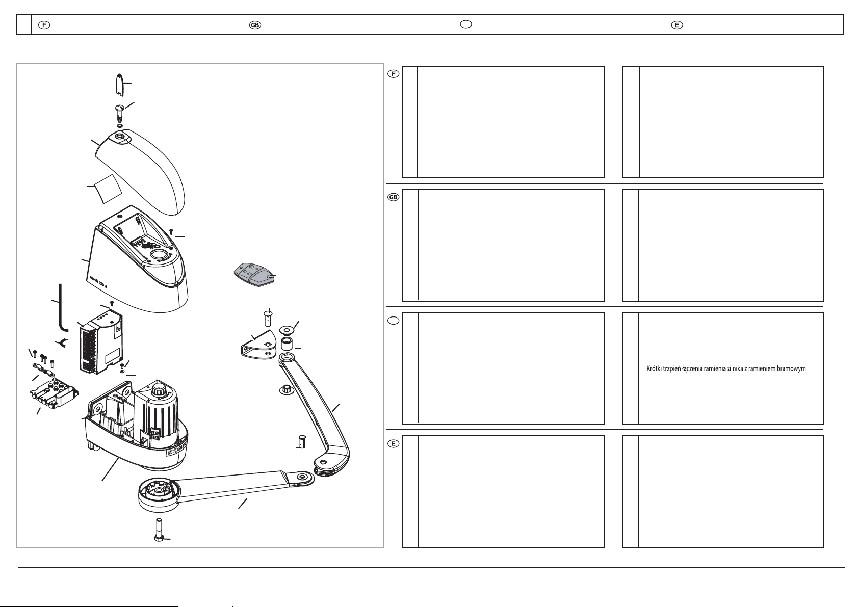
12xruetoM
22xruetomsarB
32xliatropsarB
42xliatropepahC
5Boitierélectronique de command
62xruetomtopaC
74xruetomtopacsiV
81x
1x
noitamrofnietraC
9C 2xtopacelcrevuo
10 4xelcrevuocsiV
11 2xelcrevuocélC
12 1xeuqinortceléreitiobsiV
13 Pa 2xlifess
14 4xelbacerreS
15 8xelbacerressiV
16 1xerretedsiV
17 1xerretedellednoR
18 8xedirb72x21ellednoR
19 2xruetomsarB/exasiV
20 Axe court bras moteur / Bras portail x 2
21 Axe long bras portail / Chape x 2
22 Ba 4xliatropsarbeug
23 2xliatropsarbruessitromA
24 Télécommandes Keytis 4 RT
S
x 2
25 1xennetnA
26 Str 1xelullecpa
1
8
22
21
16
20
19
14 17
18
15
2
3
11
12
13
4
10
5
7
9
6
23
Composition du kitComposition of kitWykaz elementów Composición del kit
2
12xrotoM
22xmrarotoM
32xmraetaG
42xkrofetaG
51x
x
xoblortnoccinortcelE
62xrevocrotoM
74xwercsrevocrotoM
81xdracnoitamrofnI
9C 2xrevo
10 C 2xwercsrevo
11 C 2xyekrevo
12 1xwercsxobcinortcelE
13 2xtemmorG
14 4xpmalcelbaC
15 8xwercspmalcelbaC
16 1xwercshtraE
17 Earth w 1xrehsa
18 8xrehsaw72x21pmalC
19 2xwercsmrA/tfahsrotoM
20 Motor arm/ Gate arm short shaft x 2
21 Gate /Fork arm long shaft x 2
22 Ga 4xgnihsubmraet
23 Gate arm shock absorbe
r
x 2
24 Remote control Keytis 4 RTS x 2
25 1xannetnaeriW
26 C 1xtnuhssʼlle
12x
22x
32x
42x
x
5
62x
74x
81
1
x
92x
10 2x
11 2x
12 1x
13 2x
14 4x
15 8x
16 1x
17 1x
18 8x
19 2x
20
21
22 4x
23
2x 2x
2x
24 2x
25 1x
26 1x
12xrotoM
22xrotomedozarB
32xnótropedozarB
42xnótropedalliuqroH
5Caja electrónica de mand
o
x 1
6Tapa d 2xrotomle
7Tornillo de la tapa del motor x 4
8Ta 1xnóicamrofniedatejr
9Cub 2xapataledatrei
10 To 2xatreibucaledollinr
11 2xatreibucaledevalL
12 Tornillo de la caja electrónica x 1
13 Pas 2xsoliha
14 4xselbacateirpA
15 Tornillo de aprietacable
s
x 8
16 To 1xarreitedollinr
17 1xarreitedalednarA
18 8xadirb72x21alednarA
19 Tornillo de eje / Brazo de motor x 2
20 Eje corto de brazo de motor / Brazo de
portó
n x 2
21 Eje largo de brazo de portón / Horquill
a
x 2
22 Anillo de brazo de portó
n
x 4
23 Amortiguador de brazo de portón x 2
24 2xSTR4sityeKrosimE
25 1xanetnaedelbaC
26 Co 1xsalulécnóixen
24
25
26
Silnik
Ramię silnika
Ramię bramowe
Jarzmo mocujące do bramy
Elektroniczny panel sterujący
Pokrywa silnika
Śruba mocowania pokrywy silnika
Tabliczka informacyjna
Pokrywa napędu
Śruba mocowania pokrywy napędu
Klucz do mocowania pokrywy napędu
Śruba mocowania panelu elektronicznego
Gniazdo do przyłączenia kabli zasilających
Zacisk przewodów
Śruba zacisku przewodów
Śruba podłączenia uziemienia
Podkładka śruby podłączenia uziemienia
Podkładka śruby mocującej
Śruba mocowania trzonu silnika do ramienia
Trzpień łączenia bramy z ramieniem bramowym
Tuleja łączenia bramy z ramieniem bramowym
Amortyzator ramienia bramowego
Pilot zdalnego sterowania Keytis 4 RTS
Antena
Zwora
PL
PL
2
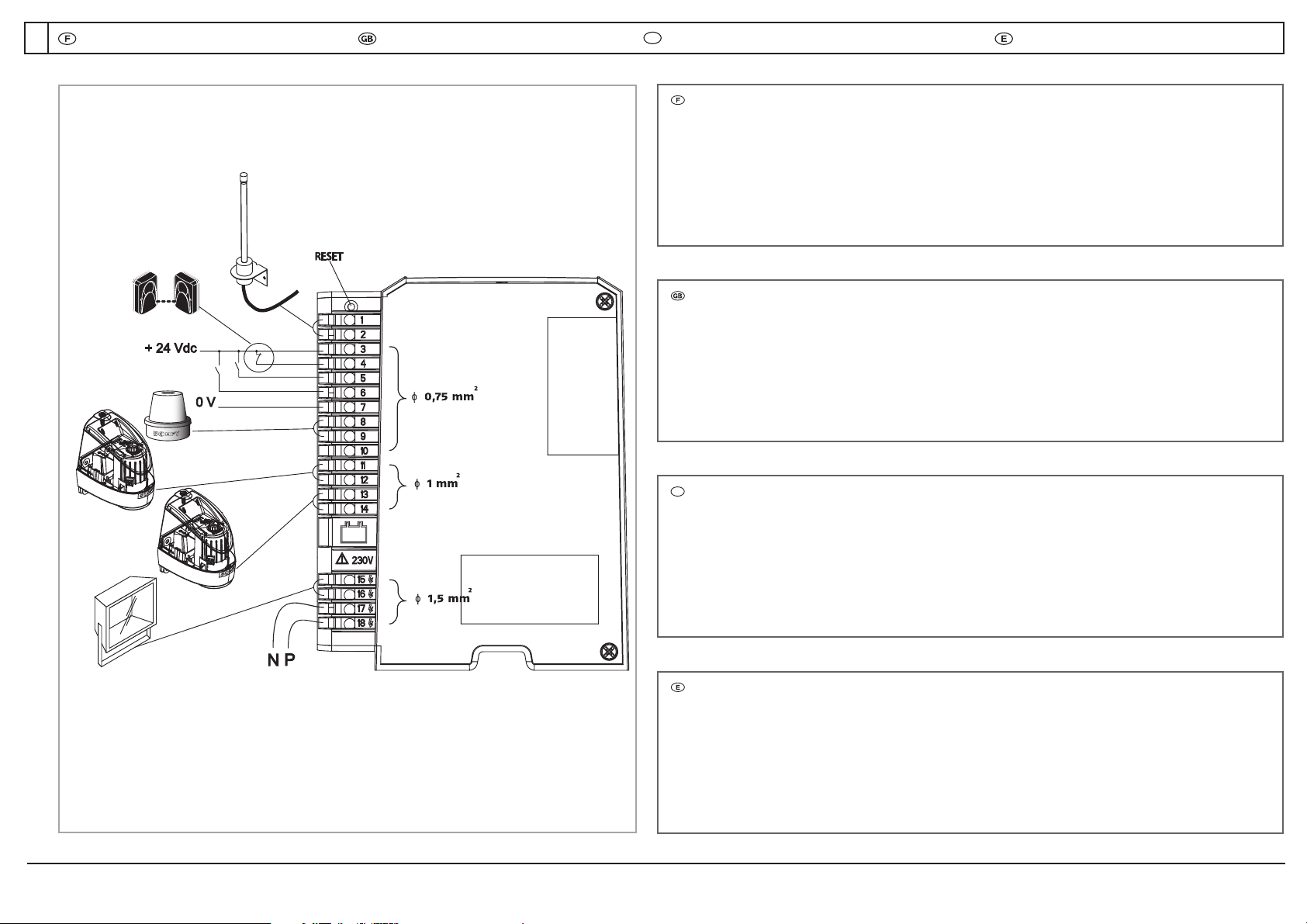
1+ 2 Antenne
3 + 4 Jeu de cellules
3 + 5 Commande pourlʼouverture totale
3 + 6 Commande pourlʼouverture piétonne
3 + 7 Sortie permettant dʼalimenter les accessoires (24Vdc / 12Vac)
8 + 9 Feu orange (sortie clignotante 24V 15 W maxi)
8 + 10 Gâche électriq ue selon cas spécifique.
11 + 12 Moteur 1 (24V)
13 + 14 Moteur 2 (24V)
15 + 16 Eclairage de zone (500Wmaxi en 230V)
17 + 18 Cable dʼalimentation secteur 230V
Description du boîtier électroniqueElectronic control box descriptionElektroniczny panel sterujący Descripción de la unidad electrónica
3
1+ 2 Antenna
3 + 4 Input for Photocell contacts
3 + 5 Control for total opening
3 + 6 Control for pedestrian opening
3 + 7 Output powering the accessories (24Vdc / 12Vac)
8 + 9 Flashing output for one orange light (24V - 15W)
8 + 10 Electric strike plate according to specific case
11 + 12 Motor 1 (24V)
13 + 14 Motor 2 (24V)
15 + 16 Area lighting output (500Wmaximum at 230V)
17 + 18 Power supply cable 230V
1+ 2 Antena
3 + 4
Entrada para el kit células fotoeléctricas
3 + 5
Orden para la abertura total
3 + 6
Orden para la abertura peatonal
3 + 7
Salida que permite alimentarlos accesorios (24Vdc / 12Vac)
8 + 9
Salida luz intermitente, permite alimentar una luz naranja (24V – 15W)
8 + 10 Conexión eléctrica según caso específico
11 + 12 Motor 1 (24V)
13 + 14 Motor 2 (24V)
15 + 16
Salida de iluminación de zona (500W máximo en 230V)
17 + 18
Cable de alimentación
230V
PL
PL
1+2 Antena
3+4 Wejścia dla fotokomórek
3+6 Sygnał dla otwarcia furtki
3+5 Sygnał otwarcia całkowitego
3+7 Wyjście zasilania dla akcesoriów
8+9 Wyjście światła ostrzegawczego (24VDC / 12VAC)
8+10 Zaciski ektryczne do wykorzystania w szczególnych przypadkach
11+12 Silnik 1 (24V)
13+14 Silnik 2 (24V)
15+15 Wyjście zasilania oświetlenia (max. 500X, 230V)
17+18 Zasilanie 230V

3
L ≤ 2 m
H ≤ 2 m
P ≤ 200 Kg
166
Vérifications avant le montage Checking before assemblyKontrola przed montażem Verificaciones antes del montaje
4
Your gates must have end stops to limit their travel and theirposition is
determined by the opening angle (< or 120°). It is not ne cessary for the
two gates have the same angle of opening.
Los batientes de la puerta deben ser detenidos porlos topes con tal de
delimitar la carrera. El ángulo de apertura no debe exceder los 120°. No es
necessario que los batientes tengan el mismo angulo de apertura; por
ejemplo uno puede abrirse a 90°yel otro a 120°. El operadoral efectuar
su autoaprendizaje, tendrá en cuenta de forma automática estos datos.
Cotas del operador (mm)
Overall dimensions (mm)
Encombrement général (en mm)
Les piliers présentant un faux aplomb nécessitent lʼutilisation dʼune
platine spéciale. De même, quand lʼun des trous de fixation des
pattes pilier est dans le vide ou proche de lʼangle du mur, il est
impératif de positionner la platine support SOMFY.
Si le portail ne comporte pas de renforts, prévoir des contre-plaques
en métal (exemple: 15x15cm et 4mm dʼépaisseur) pour la fixation des
équerres.
If one of the attachment holes of the pillar anchors lies in space or
near the corner of a wall, then the SOMFYsupport plate provided as an
option must be used.
If your gates do not have reinforcement, it is necessary to provide
reinforcing plates for attaching the brackets ( a 15x15 cm metal
plate, 4mm thick for example).
Pilares que presentan una falsa verticalidad, soportes irregulares:
utilice la placa soporte SOMFY. (accesorio)
Puerta sin refuerzos: es necesario in stalar contraplacas para la
fijacion de los soportes (por ejemplo, una placa de metal de
15 x 15 cm con 4mm de espesor).
Ámbito de aplicación
Scope of application
Domaine dʼapplication
Les vantaux doivent être arrêtés par des butées fixées solidement au sol
afin que leur course soit délimitée à lʼouverture comme à la fermeture.
Lʼemplacement de ces butées sera déterminé par lʼangle dʼouverture des
vantaux (< ou = à 120°). Lʼangle dʼouverture des deux vantaux peut être
différent.
PL
PL
Brama musi być wyposażona w ograniczniki zatrzymujące w celu
określenia jej stopnia otwarcia i położenia otwartego (< lub równe 120°).
Nie jest to konieczne dla dwóch skrzydeł mających ten sam kąt otwarcia.
PL
Jeśli jeden z otworów mocujących kotwy do słupa wypada poza nim lub
na krawędzi konieczne jest użycie dodatkowo płyty wzmacniającej,
dostarczanej opcjonalnie.
Jeśli brama nie ma wzmocnień, wówczas należy użyć płyt wzmacniają-
cych do montażu wsporników (na przykład 15x15 cm, 4 mm grubości).
PL
Możliwości zastosowania
PL
Ogólne wymiary
4
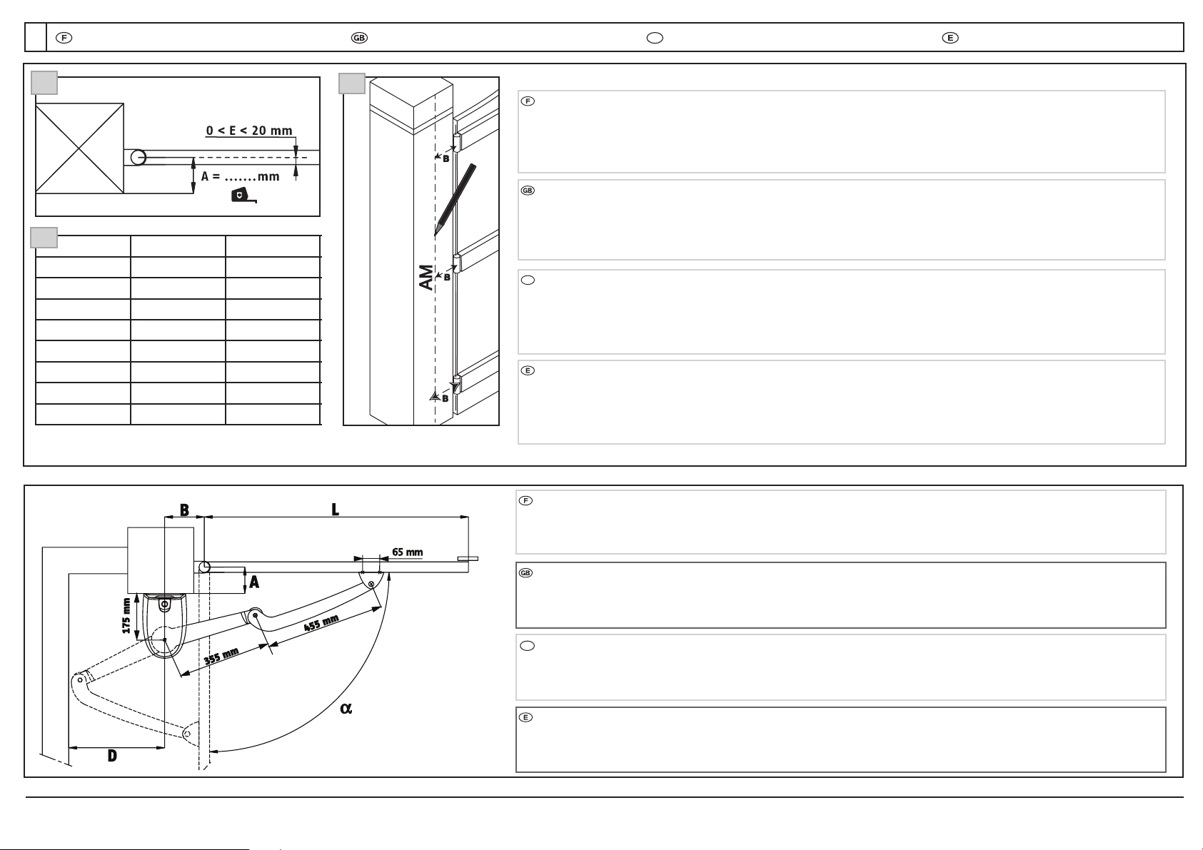
65 mm
Par sécurité, verifier la distance D: distance entre lʼaxe AM et le 1er obstacle côté opposé au vantail (écoinçon) D ≥405 mm.
NB : La distance L doit être comprise entre 800 mm et 2000 mm. Si L < 1250, lʼutilisation dʼun jeu de cellules photoélectriques
est obligatoire.
A (mm) αmax (°) B (mm)
0 120 205
0 110 160
0 105 150
50 100 150
100 95 150
150 90 150
200 90 150
250 90 150
1
NB : Les valeurs indiquées ont été calculées pour la configuration présentée (axe des gonds et axe du vantail identique).
Dans le cas ou ces deux axes ne seraient pas identiques (gonds déportés), les valeurs dʼangle dʼouverture maximum des
deux vantaux seront diminuées.
1 - Mesurer la distance A(distance gonds pilier).
2 - Se reporter au tableau et choisir la côte en fonction de lʼangle dʼouv erture souhaité.
3 - Tracer lʼaxe AM sur le pilier en respectant la côte Bchoisie.
3
By safety, check distance B: distance between AM axis and the 1 st obstacle on the side opposite the gate (cornerpiece)
D ≥405 mm.
NB: Distance L must range between 800 mm and 2000 mm, if L < 1250, you must use a set of photocells.
Por seguridad, verificar la distancia D: distancia entre el eje AM y el 1 er obstáculo del lado opuesto al batiente (rinconera)
D > 405 mm.
nota: la distancia L debe estar comprendida entre 800 mm y 2000 mm, si L < 1250, la utilización de un juego de células
fotoeléctricas es obligatoria.
Processus de montage Assembly processProces montażu Proceso de montaje
5
2
NB: the values specified have been calculated for the configuration presented (identical hinge axes and gate axis). Should
these axes not be identical (offset hinges), the maximum opening angle values of both gates will be hidden.
1 - Measure distance A(hinge-pillar distance).
2 - Refer to the table, and choose size Baccording to the opening angle required.
3 - Mark the AM axis on the pillar, while complying with the Bsize chosen.
Nota: Los valores indicados se han c alculado para la configuración presentada (eje de los goznes y eje del batiente
idénticos). En caso de que estos dos ejes no fueren idéntic os (goznes desplazados), los valores de ángulo de apertura
máxima de los dos batientes se disminuirían.
1 - Medir la distancia A(distancia gozne pilar).
2 - Remitirse al cuadro y elegiren función del ángulo de apertura deseado, la cota Bcorrespondiente.
3 - Trazar el eje AM sobre el pilar respetando la cota Belegida.
PL
PL
NB: wartości wyspecykowane zostały obliczone dla przedstawionej konguracji (identyczne położenie osi zawiasów i osi
bramy). Jeśli położenie osi nie będzie identyczne (przesunięcie zawiasów), wówczas maksymalny kąt otwarcia obu skrzydeł
będzie różny.
1 -Zmierzyć dystans A – (odległość od zawiasów do krawędzi słupa).
2 -Określić wartość dystansu B według tabeli, zgodnie z żądanym kątem otwarcia.
3 - Oznaczyć oś AM na słupie, zgodnie z wybraną wartością B.
PL
Ze względów bezpieczeństwa sprawdzić wymiar D: odległość pomiędzy osią AM i pierwszą przeszkodą dla ramion napędu po
stronie przeciwnej do położenia skrzydła bramy (wielkość narożnika) D>= 405 mm.
NB: Dystans L musi zawierać się pomiędzy 800 mm a 2000 mm; jeśli L<1250 należy użyć fotokomórek.
5
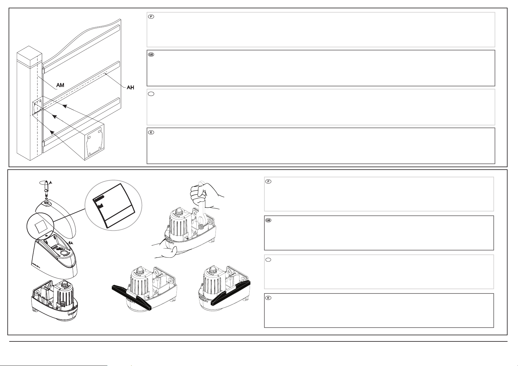
Tracer un axe horizontal AH au milieu du renfort, per pendiculaire à l'axe de rotation du portail.
Prolonger cet axe sur le pilier jus qu'à l'intersection avec AM.
Placer le gabarit à l'intersection des 2 axes et percer.
PORTAILS SANS RENFORT : si le portail ne comporte pas de renfort, placer les moteurs a environ 1/3 de la hauteur des vantaux en part ant du bas.
De plus il est nécessaire de prévoir des contre-plaques pour la fixation des chapes (par ex emple une plaque de métal de 150 x 150 x 4 mm).
name
tel
- Ouvrir le capot supérieur à lʼai de de la clé spécifique.
- Dévisser les 2 vis du capot inférieur, le retirer.
- Fixer le moteuren vérifiant le niveau.
Carte info : Pour plus de visibilité, utilis er un feutre indélébile.
Mark an AH horizontal axis in the middle of the re inforcement, perpendicularto the gate's rotation axis.
Extend this axis on the pill ar to the AM intersection.
Fit the template at the intersection of the 2 axes, and drill.
GATES WITHOUT REINFORCEMENTS: if the gate does not have reinforcements, fit the motors at about 1/3 of the height of the gates f rom th e bottom.
In addition, plan to fit backplates for securing the forks (e.g. a metal plate 150x150x4 mm).
Trazar un eje horizontal AH en medio del ref uerzo, perpendicularal eje de rotación del portón.
Prolongar este eje sobre el pilar hasta la intersección con AM.
Colocar la plantilla en la intersección de los 2 ejes y perforar.
PORTONES SIN REFUERZO: si el portón no incluye refuerzos, colocar los motores a aproximadament e 1/3 de la altura de los batientes partiendo de abajo.
Además, es ne cesario prever contraplacas para la fijación de las horq uillas (por ejemplo una placa de metal de 150 x 150 x 4 mm).
- Open the upper cover using the specific key.
- Unscrew the 2 lower cover screws, remove it.
- Fit the motorwhile checking the level.
Info card: For more visibility, use a permanent ink.
- Abrir la tapa superior con la ayuda de la llave específica.
- Desatornillarlos 2 tornillos de la tapa inferior, retirarla.
- Fijar el motor verificando el nivel.
Tarjeta de información:Para mayor visibilidad, utilizar un marcadorpermanente.
Oznaczyć oś poziomą AH na środku wzmocnienia, prostopadle do osi otwierania skrzydła. Następnie przedłużyć tę oś na słupku do przecięcia z osią AM.
Ustawić szablon w miejscu przecięcia osi i wywierć otwory.
Skrzydła bez wzmocnienia: jeśli skrzydła nie maja wzmocnienia napęd powinien być przymocowany do bramy w 1/3 wysokości od dołu. Dodatkowo należy użyć
wsporników w celu zabezpieczenia mocowania bramy (np. metalowe płytki o wymiarach 150x150x4 mm).
PL
PL
- Otworzyć pokrywę górną przy użyciu dedykowanego klucza
- Odkręcić dwie dolne śruby i usunąć je
- Ustalić położenie napędu po sprawdzeniu wypoziomowania
Karta informacyjna:dla lepszej widzialności należy użyć niezmywalnego tuszu.

6
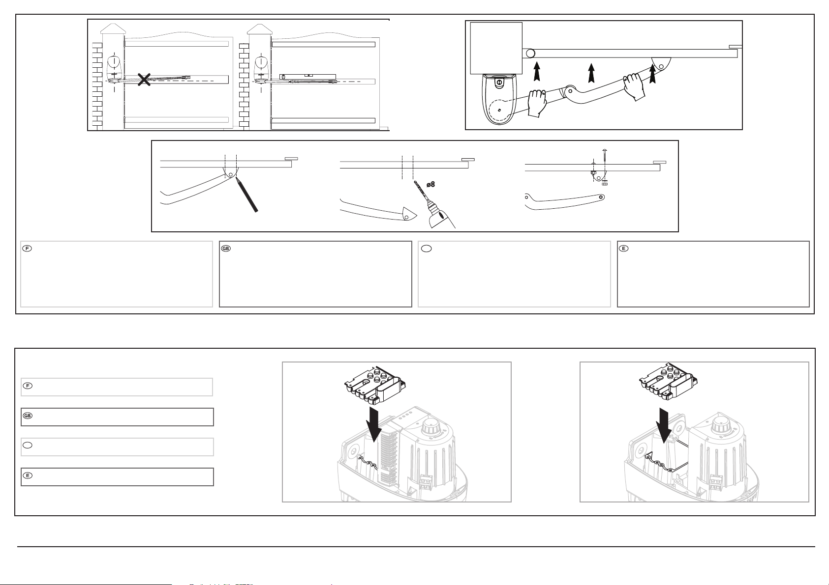
Assembler les bras sans utiliser dʼoutil afin de ne pas endommager les bagues.
Assemble the arms without using tools while preventing to damage the bushings.
Ensamblar los brazos sin utilizar herramientas para no dañar los anillos.
Déverrouillerle bras des moteurs à lʼaide du bouton situé surle dessus du moteur.
En position déverrouillée, les bras doivent être manoeuvrés lentement pour évit er la détérioration
des moteurs.
( Cadenas fermé: bras verrouillés; cadenas ouvert: fonctionnement manuel)
Unlock the motorarms using the knob located on the top of the motor.
In the unlocked position, handle the arms gently to prevent damaging the motors.
(Padlock closed: arms locked; padlock open: manual operation)
Desbloquear el brazode los motores con la ayuda del botón situado en la parte superior del motor.
En posición desbloquear,los brazos se deben manipul ar lentamente para evitarel deteriorode
los motores.
(Candado cerrado: brazos bloqueados; c andado abierto: funcionamiento manual)
PL
Złożyć ramiona bez używania narzędzi aby zapobiec uszkodzeniu tulejek
PL
Odblokować ramiona napędu przy pomocy przełącznika umieszczonego na górze silnika.
W położeniu odblokowanym należy delikatnie obchodzić się z ramionami aby zapobiec uszkodzeniu
napędów. (Kłódka zamknięta – ramiona zablokowane; kłódka otwarta – operowanie ręczne)
7
Déplier les bras vers le portail, en les alignant avec le
moteuret le renfort du portail. Marquer les entraxes
pour la fixation des chapes surle portail. Retirer les
bras, percer et fixer les chappes.
NB : avant de percer, vérifier que le bras est bien
horizontal.
Montage des passe-câbles sur les 2 moteurs.
2M1M
Unfold the arms toward s the gate, while aligning
them with the motorand gate reinforcement. Mark
the centre distances to fit the forks onto the gate.
Remove the arms, drill, and secure the forks.
NB: before drilling, check tha t the arm is horizontal.
Desplegar los brazos hacia el portón, alineándolos con
el motor y el refuerzo del portón. Marcar los entreejes
para la fijación de las horquillas sobre el portón.
Retirar los brazos, perforar y fijar las horquillas.
Nota:antes de perforar, verificar que el brazo
esté horizontal.
Fitting the cable grommets on the 2 motors.
Montaje de los pasacables en los 2 motores.
PL
Rozłożyć ramiona w stronę skrzydeł, ustawiając je w linii
prostej z napędem i wzmocnieniem bramy. Oznaczyć miejsce
zamocowania jarzma mocującego do bramy. Odsunąć
ramiona, wywiercić punkty montażowe i zamontować jarzma.
UWAGA : Przed rozpoczęciem wiercenia otworów należy
upewnić się że ramiona są wypoziomowane.
PL
Włożyć zaciski kabli zasilających do dwóch napędów.
AntenneAntenna Antena Antena
8
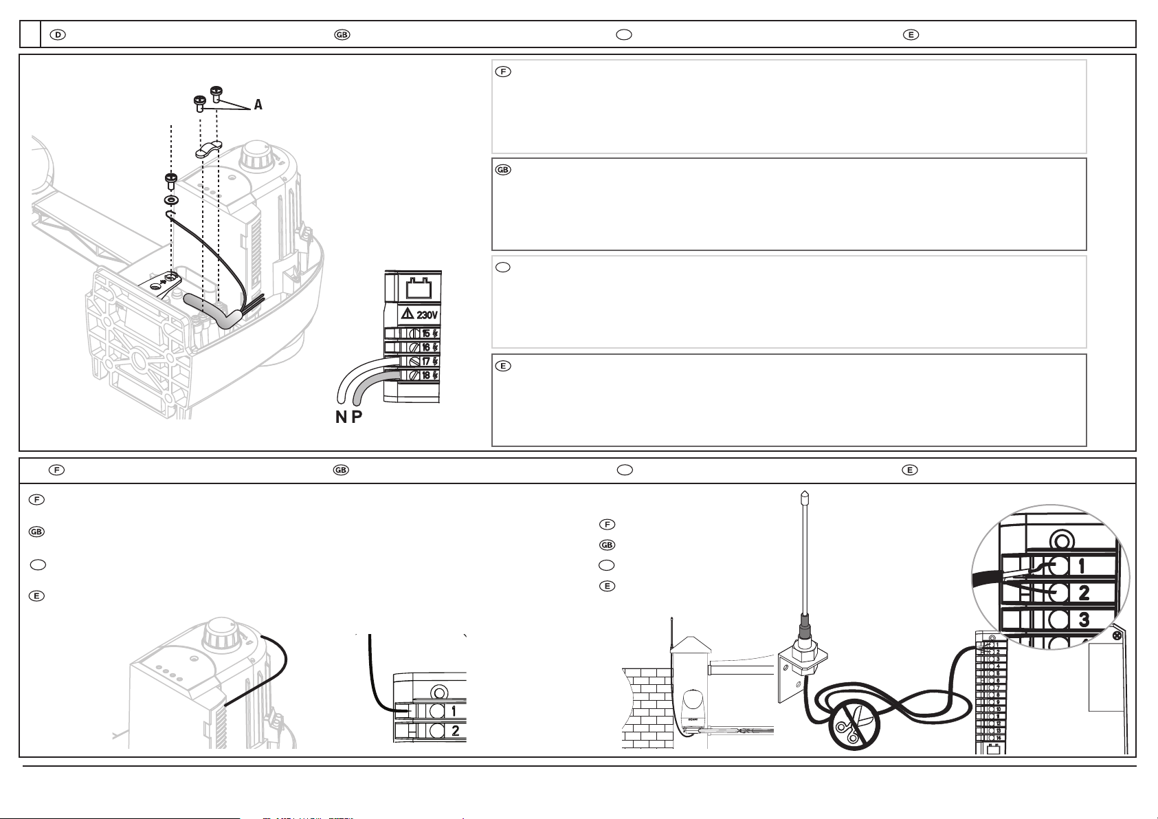
Un moyen de déconnexion omnipolaire de lʼalimentation doit être prévu:
- soit par un câble dʼalimentation muni dʼune fiche de prise de courant IP 54 minimum.
- soit par un interrupteur assurant une distance de sép aration des contacts dʼau moins 3mm sur chaque pôle
- cf norme EN 60335-1
Attention ! il peut être nécessaire de retirer lʼécrou de fixation de la bride pourpouvoir visser la vis (A) situé contre la bride .
Raccorder le fil de terre secteur à lʼemplacement prévu à cet effet sur la bride.
Antenne dʼorigine
La position et le pliage de lʼantenne est nécess aire au bon fonctionnement de la radio. (Cf ci-dessous)
Original antenna
Position and fold the antenna as shown to en sure proper radio operation. (see below).
Antena de origen
La posición y el plegado de la antena son necesarios para el correcto funcionamiento de la radio (ver a continuación).
Antenne déportée ( option )
Remote antenna ( option )
Antena zewnętrzna (opcjonalna)
Antena desplazada ( opción )
Branchements ConnectingPodłączenie Conexiones
6
A means by which the power supply can be disctonnected must be integrated into the system. 2 solutions are possible:
- a cable with a plug IP54 mini
- a switch with a gap of at least 3mm between the contacts on each pole.
- cf EN 60335-1 standard
Caution ! You may have to remove the flange's securingnut to tighten the flange's screw (A).
Connect the mains earth wire at the locatio n designed to this effect on the flange.
El operador debe contar con un sistema que permita su desconexion. Es posible realizarlo a través de 2 sistemas:
(norma cf EN 60335-1)
- Un cable con enchufe IP54 minima
- Un interruptor con una distancia minima de 3mm entre los contactos de cada polo.
Atención, puede ser ne cesario retirar la tuerca de fijación de la brida para pod er atornillarel tornillo (A) sit uado contra la
brida. Conectarel hilo de tierra de la red eléctrica en el emplazamiento previsto para este efecto en la brida.
PL
PL
Należy przewidzieć sposób odcinania napięcia zasilającego. Możliwe są dwa rozwiązania zgodne z normą EN 60335-1:
- przewód zakończony wtyczką IPS 54 mini
- przełącznik dwubiegunowy ze szczeliną powietrzną min. 3 mm dla każdego bieguna
Uwaga: W celu dokręcenia śruby mocującej (A) może zajść potrzeba usunięcia nakrętki zabezpieczającej.
Podłączyć przewód ochronny z wiązki zasilającej do przeznaczonej w tym celu kryzy.
PL
PL
PL
Oryginalna antena
W celu zapewnienia prawidłowego działania ustawić i ukształtować antenę jak pokazano na rysunku.
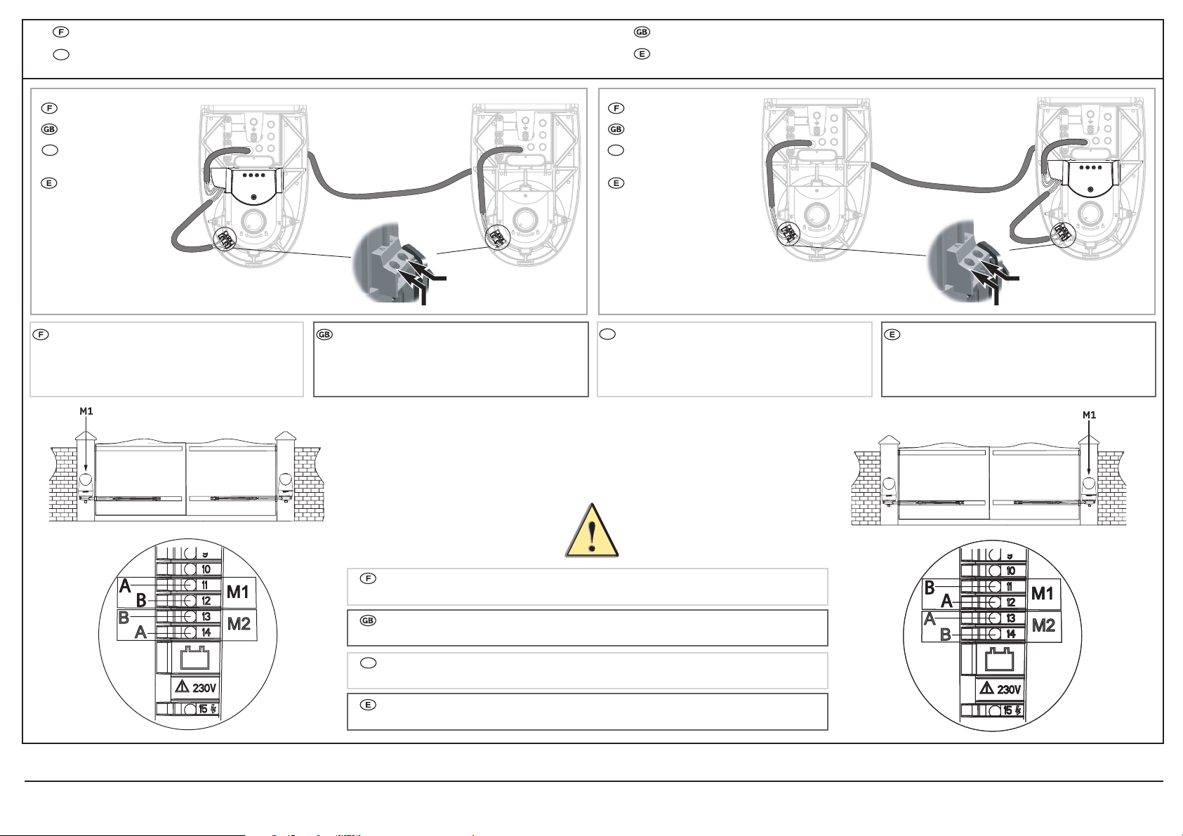
Le moteur M1 est toujours connecté aux bornes 11 et 12.
Le moteur M2 est toujours connecté aux bornes 13 et 14.
The motorM1 is always connected between terminals 11 and 12.
The motorM2 is always connected between terminals 13 and 14.
El motor M1 está siempre conectado a los bornes 11 y 12.
El motor M2 está siempre conectado a los bornes 13 y 14.
Raccordement des moteurs au boîtier de commande Connecting the motors to the control unit
Podłączenie napędów do sterownika Conexiones de los motores a la caja de mando
9
Le moteur M1 est installé sur le
pilier du vantail qui sʼouvre en
premieret se referme en
dernier.
The M1 motoris installed on the
gate pillar which opens first and
closes last.
El motorM1 está instalado en
el pilardel batiente, que se abre
primero y se cierra último.
Electronique à droite
Right-hand electronics.
Elektronika w prawym
napędzie
Electrónica a la derecha.
Electronique à gauche
Left-hand electronics.
Elektronika w lewym
napędzie
Electrónica a la izquierda.
A
B
A
B
PL
PL
PL
PL
Napęd M1 jest instalowany do
tego skrzydła które otwiera się
pierwsze i zamyka ostatnie.
PL
Napęd M1 jest podłączany pomiędzy zaciski 11 i 12.
Napęd M2 jest podłączany pomiędzy zaciski 13 i 14.
Other manuals for Axovia 220A
2
Other SOMFY Door Opening System manuals


Popular Door Opening System manuals by other brands


SECO-LARM
SECO-LARM SD-7104SGEX1Q manual

MEILLER
MEILLER MiDRIVE twinCAN Installation instruction

Dormakaba
Dormakaba TS 93 G EN 2-5 Mounting instructions

Falcon
Falcon SC 71 SERIES Installation instruction

Overhead door
Overhead door RMX DRAWBAR manual

Assa Abloy
Assa Abloy SARGENT 1130-HU Series installation instructions


