DEUTSCHTEC SLH Series User manual

Installation manual
Deutschtec GmbH
Am Fuchsbau 13
15345 Petershagen/
Eggersdorf Deutschland
Phone: +49 (0)3341 30 22 4 - 0
Fax: +49 (0)3341 30 22 4 - 25
www.deutschtec.de
SLH Series

Contents
1EN.09.09052022 2EN.09.09052022
INTRODUCTION 3
SYMBOLS OF THE MANUAL 3
1 GENERAL INFORMATION OF THE PRODUCT 4
1.1 Product Introduction 4
1.1.1 SLH239 4
1.1.2 SLH240 4
1.1.3 SLH240/H 4
1.1.4 SLH240ES 4
1.2 Technical Specications 5
1.3 Copyright 6
1.4 Standards 6
1.5 Warranty Guidelines 6
1.6 Declaration of Incorporation 7
1.7 Certication 8
1.8 Signage 9
2 CONTENTS OF DELIVERY 10
2.1 Operator Kit 10
2.2 SLH Prole Set 12
2.3 Accessories 13
3 ASSEMBLY AND INSTALLATION 14
3.1 Precautionary Measures 14
3.2 Required Tools 15
3.3 Technical Drawings 16
3.3.1 Two-leaves door version (TBS Frame) 17
3.3.2 One-leaf door version (TBS Frame) 17
3.4 Installation Steps 17
3.4.1 On-Site Preparation 17
3.4.2 Aluminum Base Prole 17
3.4.3 Stainless Steel Prole & Rubber Prole 19
3.4.4 Rubber Track Prole & Aluminum Track Prole 19
3.4.5 Standard Distance for Opening (mm) 20
3.4.6 Check the Layouts 20
3.4.7 Installing the Stopper 21
3.4.8 Idler Pulley 21
3.4.9 Power Supply 22
3.4.10 Gear Motor 22
3.4.11 Control Unit 22
3.4.12 Backup Gear Motor 23
3.4.13 Battery 23
3.4.14 Hanger, Roller and Belt Holder 23
3.4.15 Inspecting the Mechanical System 25
3.4.16 Inspecting the Electrical System 25
3.4.17 Mounting the Frame Fixed Leaves 26
3.4.18 Mounting the Frame Movable Leaves 26
3.4.19 Electric Lock (Optional) 27
3.4.20 Timing Belt 28
3.5 Starting Up the Operator 28
3.5.1 Standard Version 28
3.5.1.1 Without digital key 28
3.5.1.2 With digital key 28
3.5.2 Escape version 29
3.6 Modifying the Parameters 39
3.7 Sensors Setup Table 40
3.8 Wiring diagrams 41
3.8.1 ZENSAFE Sensor 41
3.8.2 BEA ZEN/ZENSAFE sensor 41
3.8.3 BEA IXIO-DT3 Sensor 49
3.8.4 BEA VIO sensor 50
3.8.5 Optex OA-Flex Sensor 51
3.9 Block Diagram 53
3.9.1 Standard Version 53
3.9.2 Escape Version 53
4 MAINTENANCE SERVICE 54
4.1 Precautionary Measures 54
4.2 Fuse Replacement 54
4.2.1 Changing primary side fuse 54
4.2.2 Changing secondary side fuse 54
4.3 Maintenance Check 55
4.4 Timing Belt Tension 56
4.5 Mechanical Faults 56
4.6 Troubleshooting 57
4.6.1 Malfunctions 58
4.6.2 LED status (error codes) 59
5 USER INSTRUCTIONS 61
5.1 Precautionary measures 61
5.2 Main elements of the system 62
5.3 Mechanical key switch 63
5.4 Digital key switch 66
5.4.1 Operating the system with the digital key switch 66
5.4.2 Main menu 67
5.5 System behavior 68
5.5.1 Closing cycle 68
5.5.2 Opening cycle 68
5.6 Failures 69
5.7 Error handling 69
5.7.1 Handling errors by mechanical key switch 69
5.7.2 Handling errors by digital key switch 69
5.8 Mandatory Routine Maintenance 69
5.9 Cleaning 70
6 DISABLING AND DISMANTLING 70

3
- Maintenance
In this booklet, the installation process is predesignated for the engineers who install service SLH239, SLH240,
SLH240/H and SLH240ES operators.
Introduction
- System specifications
This guide is for service engineers who service SLH239, SLH240, SLH240/H and SLH240ES operators and
gives information on:
- Assembly, installation and settings
- User guidance
This manual uses the following symbols and the keywords indicate hazards that pose a risk to life and limb:
Symbols of the manual
NOTICE: An important hint.
INFORMATION: An important information.
DANGER: A hint representing a danger that immediately leads to death or
severe injury.
WARNING: A hint representing a danger that can lead to death or severe
injury.
EN.09.09052022
DANGER
WARNING
4
1 General Information of the Product
1.1 Product Introduction
Outstanding quality and unique design have made the perfect combination in Deutschtec SLH products.
These highly intelligent models enjoy incredible strength as well. Employing world-famous German
technology has made Deutschtec SLH series into robust and sturdy products which will easily handle heavy
weights.
Deutschtec SLH239 is your best option for interior or exterior applications with high traffic where normal glass
and average-sized door will do just fine. This reliable model is an excellent combination of futuristic design
and top-notch technology. Its stainless steel track profile offers strength and longevity. Its rubber
profile has the gift of quietness with it. SLH239's highest standards ensure its top-of-the-range quality.
1.1.2 SLH240
Deutschtec SLH240 is your ultimate solution for demanding interior or exterior applications or where tall or
wide heavy doors and double or especially triple-glazing glass is a necessity. This model has brought superior
strength and incredible resistance to wear together with beauty and elegance. Due to its rubber profile, you
hear nothing more than a whisper. Its stainless steel track profile promises to stay with you for all time and
make your choice energy-saving and cost-effective. SLH240 has been certified as a product which satisfies all
safety needs.
Deutschtec SLH240/H is your ultimate solution for demanding interior or exterior applications or where tall or
wide heavy doors and double or especially, triple glazing glass is a necessity. This model has brought
superior strength and incredible resistance to wear together with beauty and elegance.
Deutschtec SLH240ES is your ultimate solution for having highest levels of safety in escape routes. This system
drives doors by one Gear Motor and Controller (Slave) for opening cycles and the other Gear Motor and
Controller (Master) for closing cycles. Such function ensures more than doubled life time and silent operation.
In emergency cases both sets are able to open the door.
1.1.3 SLH240/H
1.1.1 SLH239
1.1.4 SLH240ES
EN.09.09052022

6
1.3 Copyright
This manual was prepared and issued by Deutschtec GmbH. All rights are reserved. The information in this
manual is the property of Deutschtec GmbH; located in Germany. Disclosure of this information or any part of
it to third parties is not permitted, except with prior and explicit written permission of Deutschtec GmbH.
Deutschtec GmbH has the reserved rights to improve its products without notice. Therefore, it is possible that
the installed products show some differences from the description in this manual. This manual is based on the
standard product.
1.4 Standards
These operators in agreement with following standards:
- DIN 18650
- EN 16005
- EN ISO 13849
- EU low voltage directives
- EU EMC directives
- EN 60335
1.5 Warranty Guidelines
Conformance with the following installation and service procedures must be maintained to assure a proper
installation and to maintain the Deutschtec warranty.
Not following installation manual may result in faulty operation, injuries and
voiding warranty.
EN.09.09052022
Specification
Specification
5EN.09.09052022
1.2 Technical Specification
SLH 240
SLH 240
SLH 240/H
SLH 240/H
SLH 240 ES
SLH 240 ES
SLH 239
SLH 239
Opening width - single panel
Opening width - double panel
Max leaf weight, single
Max leaf weight, double
Operator height
Operator depth
Opening speed
Closing speed
Hold-open time
Ambient temperature
Type of Protection
Track prole
Anti-noise rubber prole
Power supply
Power Consumption max. 250 W max. 600 W max. 250 W max. 200 W
Gear motor power
160 mm
155 mm
anti-crash
Stainless Steel /
Aluminium
1 x 150 Kg
2 x 100 Kg
1000 - 3000 mm
800 - 2000 mm
0 - 30 s
IP 20
50 W
230V/33V,50VA
(Peak 120VA)
160 mm
155 mm
anti-crash
Stainless Steel
1 x 200 Kg
2 x 150 Kg
1000 - 3000 mm
800 - 2000 mm
0 - 30 s
IP 20
100 W
230V / 28V, 120VA
Variable up to 1.1m/s
(Double leaves )
Variable up to 1.1m/s
(Double leaves )
Variable up to 1.1m/s
(Double leaves )
Variable up to 1.1m/s
(Double leaves )
Variable up to 1.1m/s
(Double leaves )
Variable up to 1.1m/s
(Double leaves )
Variable up to 1.1m/s
(Double leaves )
Variable up to 1.1m/s
(Double leaves )
160 mm
155 mm
anti-crash
Stainless Steel
1 x 200 Kg
2 x 150 Kg
1000 - 3000 mm
800 - 2000 mm
0 - 30 s
IP 20
100 W
230V/33V,50VA
(Peak 120VA)
160 mm
155 mm
anti-crash
Stainless Steel
1 x 500 Kg
2 x 300 Kg
1000 - 3000 mm
800 - 2000 mm
0 - 30 s
IP 20
100 W
230V/33V,100VA
Emergency exit routes in both directions
Mechanical key switch (Optional)
24V DC output for external accessories
Possibility of using
electromechanical lock (Optional)
Lock monitoring
Possibility of using digital
programme switch (Optional)
Read-out error memory with error
codes (with digital programme switch)
Programmable output (Optional)
Power Lock
Programmable input (Optional)
Possibility of using more software
and hardware options by using
DEAP device (Optional)
Max operation cycles with 2.2 Ah
battery (Optional)
Max operation cycles with 7.2 Ah
battery (Optional)
Possibility to adjust force limitation
according to DIN18650 and EN16005
400
1000
-
400400
10001000
-
-
-
-
-15 to + 50 C -15 to + 50 C -15 to + 50 C -15 to + 50 C

8
1.7 Certification
EN.09.09052022
7
1.6 Declaration of Incorporation
EN.09.09052022
Declaraon of Incorporaon
In accordance with Annex II section 1.B. of the EC Machinery Directive 2006/42/EC
Authors and persons responsible for creating the relevant technical documents:
Deutschtec GmbH
Am
Fuchsbau
13
15345Petershagen/Eggersdorf
Germany
We hereby declare that the incomplete machine:
Sliding Door Operator Type: SLH239, SLH240, SLH240/H and SLH240ES
as long
as
supply
is
possible
within
the
scope
of
delivery,
and
corresponds
to
the basic
requirements
of
the
following
directives
(refer
to
the
Annex
regarding
which
requirements were
met):
Harmonized standards that were used, whose references have been published in
the Ofcial Journal of the EU:
Petershagen/Eggersdorf, 17.01.2021 (Place, Date)
Requirements of Annex I of 2006/42 EC, which have been complied with. The
numbers refer to the sections of Annex:
I: 1.1.5, 1.3.4, 1.3.7, 1.5.14, 1.3.1, 1.3.2, 3.4.5, 1.2.1, 1.3.8.2, 1.4.1, 1.4.3, 1.5.1,
1.5.2, 1.5.5, 1.5.6, 1.5.7, 1.5.8, 1.5.9, 1.5.10, 1.5.13, 1.1.3, 1.1.6, 1.2.6, 1.6.3,
1.5.15, 1.3.2, 1.3.3, 1.6.1, 1.2.4.1, 1.2.4.3, 1.2.4.4, 1.2.3, (partially)
2006/42/EC Machinery Directive
2014/30/EU Electromagnetic Compatiblity Directive
EN ISO 12100:2010
EN ISO 13849-1:2015
EN 16005:2012
EN ISO 13857:2019
EN 60335-1:2020
IEC 60335-2-103:2015

10
2. Contents of Delivery
Components of SLH series are delivered in three main categories as follows:
2.1 Operator Kit
Article NO. Description Kit/set incl.
Quantity
Note: Screws and dowels are required for fastening that will be provided by the supplier.
EN.09.09052022
9
1.8 Signage
Clear signage on automatic doors is a key component of the safety system. Deutschtec has prepared several
warning signs (in accordance with ISO 7010:2020) that must be attached to the relevant parts of this product.
Signage are defined below:
Signage Interpretation Location to be attached on
This warning sign is used to show
the risk of electric shock advising to
avoid touching the component.
This warning sign shows the risk of
hand injury with moving parts.
T h i s o p a q ue d e c al i n fo r m s
pedestrians about the presence of
the transparent glazing.
This decal might be presented with
different designs.
This pictogram is mandatory for
doors with an emergency break-out
function.
This signage should be attached on
the power supply.
This signage should be attached on
the hangers inside the operator.
This opaque decal should be
placed at 1270mm ± 305mm
from the floor to the centerline of
the sign visible from both sides of
each fixed leaves.
This signage should be placed at
1270mm ± 305mm from the floor
to the centerline of the sign visible
from the opening side of the door.
Risk of Electric Shock
Risk of Crushing Hands
In Emergency Push to Open
EN.09.09052022
1000000038
1000000206
1000000057
1000000076
1000000081
1000000094
1000000108
1000000115
1000000118
1000000119
SLH Assembled Motor
100W -40V
SLH Assembled Motor
100W 24V
SLH Assembled Motor
50W -24V
SLH/PR Control Unit -
Steel Case
SLH/PR
P ower Pack Steel
Case
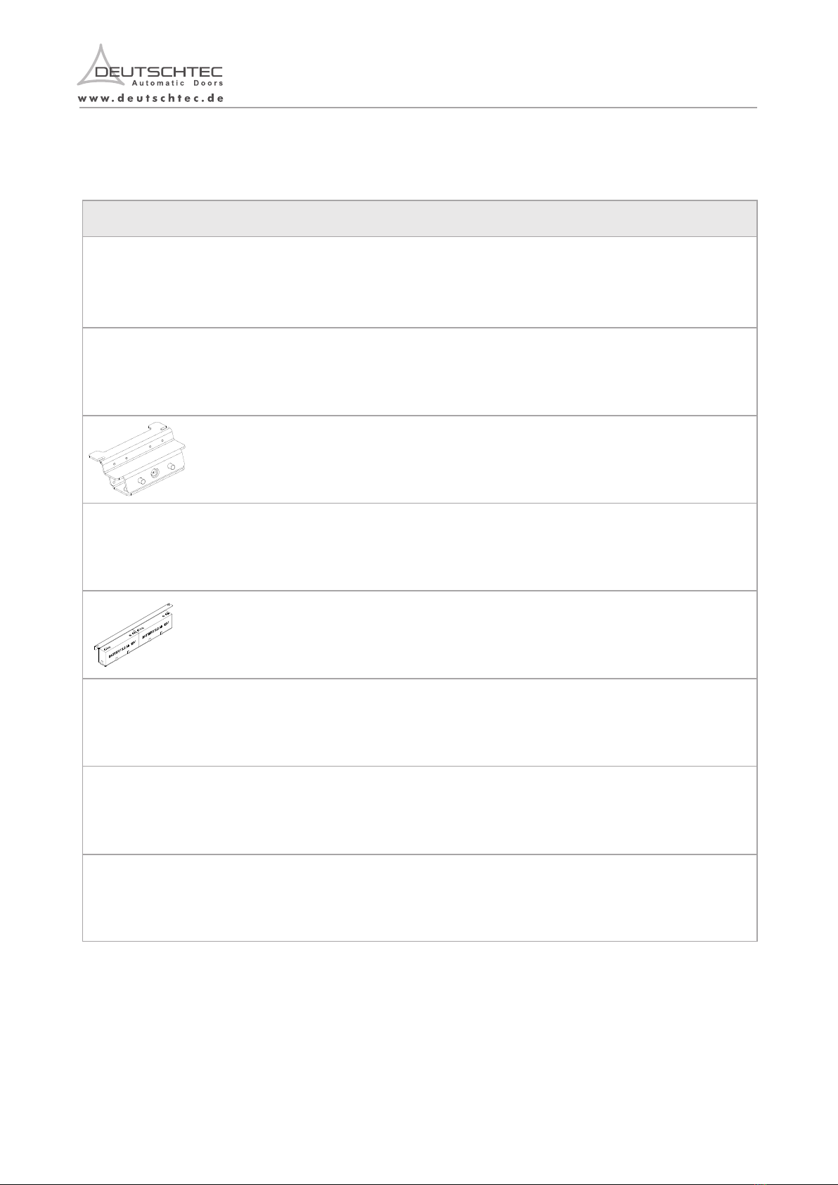
SLH Hanger & Roller
SLH Belt Clamp Set
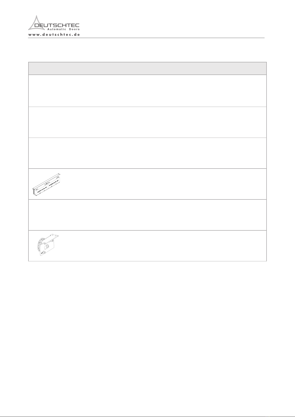
SLH Stopper Pack
SLH Cover and Cable Clip
SLH Side Cover Pack
SLH/Prime Standard
Cable Pack
2 PCS
2
PCS
1 PCS
1 Pcs.
2
PCS
1
PCS
1
PCS
1
PCS
1 Pcs.
1 Pcs.
1 Pcs.
1 Pcs
4 Pcs.
4 Pcs.
4 Pcs.
6 Pcs.
1 Pcs.
1 Pcs.
1 Pcs.
1 Pcs.
1 Pcs.
1 Pcs.
1 Pcs.
1 Pcs.
1 Pcs.
1 Pcs.
1 Pcs.
1 Pcs.
1 Pcs.
1 Pcs.
1 Pcs.
1 Pcs.
2 Pcs.
1 Pcs.
1 Pcs.
2 Pcs.
SLH240H
SLH240ES
SLH240
SLH239
SLH240ES
SLH240
SLH239
SLH240H
SLH240ES
SLH240
SLH239
SLH240H
SLH240ES
SLH240
SLH239
SLH240H
SLH240ES
SLH240
SLH23 9
SLH240H
SLH240ES
SLH240
SLH239
SLH240H
SLH240ES
SLH240
SLH239
SLH240H
SLH240ES
SLH240
SLH239
SLH240H
SLH240ES
SLH240
SLH239
SLH240H

10
2. Contents of Delivery
Components of SLH series are delivered in three main categories as follows:
2.1 Operator Kit
Article NO. Description Kit/set incl.
Quantity
Note: Screws and dowels are required for fastening that will be provided by the supplier.
EN.09.09052022
9
1.8 Signage
Clear signage on automatic doors is a key component of the safety system. Deutschtec has prepared several
warning signs (in accordance with ISO 7010:2020) that must be attached to the relevant parts of this product.
Signage are defined below:
Signage Interpretation Location to be attached on
This warning sign is used to show
the risk of electric shock advising to
avoid touching the component.
This warning sign shows the risk of
hand injury with moving parts.
T h i s o p a q ue d e c al i n fo r m s
pedestrians about the presence of
the transparent glazing.
This decal might be presented with
different designs.
This pictogram is mandatory for
doors with an emergency break-out
function.
This signage should be attached on
the power supply.
This signage should be attached on
the hangers inside the operator.
This opaque decal should be
placed at 1270mm ± 305mm
from the floor to the centerline of
the sign visible from both sides of
each fixed leaves.
This signage should be placed at
1270mm ± 305mm from the floor
to the centerline of the sign visible
from the opening side of the door.
Risk of Electric Shock
Risk of Crushing Hands
In Emergency Push to Open
EN.09.09052022
1000000038
1000000206
1000000057
1000000076
1000000081
1000000094
1000000108
1000000115
1000000118
1000000119
SLH Assembled Motor
100W -40V
SLH Assembled Motor
100W 24V
SLH Assembled Motor
50W -24V
SLH/PR Control Unit -
Steel Case
SLH/PR
P ower Pack Steel
Case
SLH Hanger & Roller
SLH Belt Clamp Set
SLH Stopper Pack
SLH Cover and Cable Clip
SLH Side Cover Pack
SLH/Prime Standard
Cable Pack
2 PCS
2
PCS
1 PCS
1 Pcs.
2
PCS
1
PCS
1
PCS
1
PCS
1 Pcs.
1 Pcs.
1 Pcs.
1 Pcs
4 Pcs.
4 Pcs.
4 Pcs.
6 Pcs.
1 Pcs.
1 Pcs.
1 Pcs.
1 Pcs.
1 Pcs.
1 Pcs.
1 Pcs.
1 Pcs.
1 Pcs.
1 Pcs.
1 Pcs.
1 Pcs.
1 Pcs.
1 Pcs.
1 Pcs.
1 Pcs.
2 Pcs.
1 Pcs.
1 Pcs.
2 Pcs.
SLH240H
SLH240ES
SLH240
SLH239
SLH240ES
SLH240
SLH239
SLH240H
SLH240ES
SLH240
SLH239
SLH240H
SLH240ES
SLH240
SLH239
SLH240H
SLH240ES
SLH240
SLH23 9
SLH240H
SLH240ES
SLH240
SLH239
SLH240H
SLH240ES
SLH240
SLH239
SLH240H
SLH240ES
SLH240
SLH239
SLH240H
SLH240ES
SLH240
SLH239
SLH240H
12 EN.09.09052022
11 EN.09.09052022
Article NO. Description
Description
1000000131
SLH Pack Screw
1 Pcs.
1 Pcs.
1 Pcs.
1 Pcs.
SLH240ES
SLH240
SLH240H
SLH239
1000000636 1 Pcs.
SLH240ES
1000000333 1 Pcs.
SLH240ES
1000000124 1 Pcs.
SLH240ES
1000000116
GN Cable Clip
6 Pcs.
6 Pcs.
6 Pcs.
6 Pcs.
SLH240ES
SLH240
SLH239
SLH240H
1000000100
SLH Idler Pully
1 Pcs.
1 Pcs.
SLH240
SLH239
SLH-240ES Data Connection
Cable and 26 Pin Connector
SLH 240 ES- Power Connection
Cable and 4 Pin Connectors
Battery Pack - GN
Quantity
Quantity
Kit/set incl.
Kit/set incl.
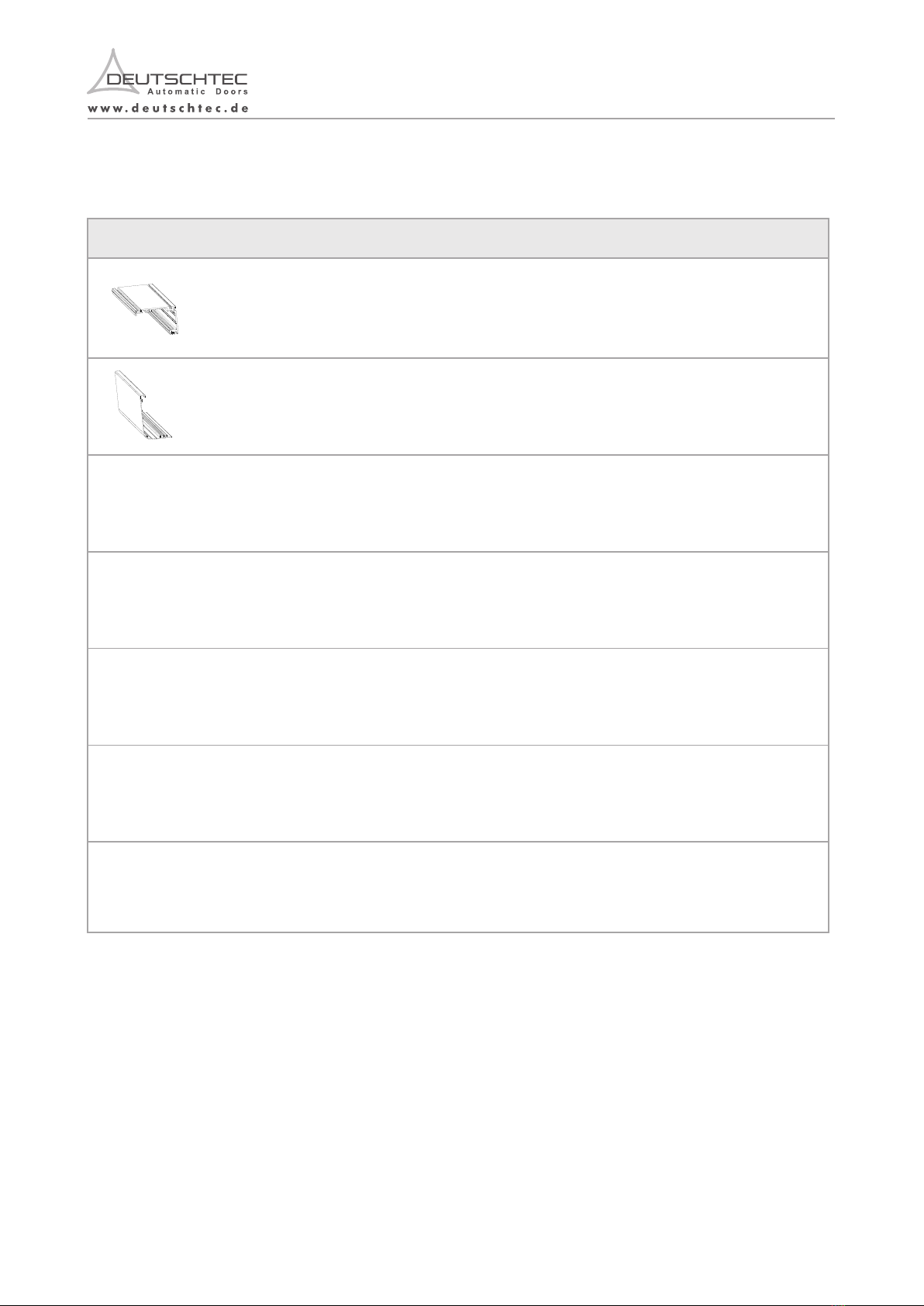
4 m SLH Rail Prole, AL Stainless Steel Prole Set
Aluminium Prole Set
Stainless Steel Prole Set
Aluminium Prole Set
Stainless Steel Prole Set
Stainless Steel Prole Set
Aluminium Prole Set
Aluminium Prole Set
Optional
4 m SLH Cover Prole, AL
4 m General Track Prole, SS
4 m General Track Prole, AL
General Rubber Prole, for SS
General Rubber Prole, for AL
4 m SLH-Back Prole
1000000002 1 Pcs.
1000000003 1 Pcs.
1000000023 1 Pcs.
1000000004 1 Pcs.
1000000024 4 Meter
1000000005 4 Meter
1000000035
Article NO.
2.2 SLH Profile Set
12 EN.09.09052022
11 EN.09.09052022
Article NO. Description
Description
1000000131
SLH Pack Screw
1 Pcs.
1 Pcs.
1 Pcs.
1 Pcs.
SLH240ES
SLH240
SLH240H
SLH239
1000000636 1 Pcs.
SLH240ES
1000000333 1 Pcs.
SLH240ES
1000000124 1 Pcs.
SLH240ES
1000000116
GN Cable Clip
6 Pcs.
6 Pcs.
6 Pcs.
6 Pcs.
SLH240ES
SLH240
SLH239
SLH240H
1000000100
SLH Idler Pully
1 Pcs.
1 Pcs.
SLH240
SLH239
SLH-240ES Data Connection
Cable and 26 Pin Connector
SLH 240 ES- Power Connection
Cable and 4 Pin Connectors
Battery Pack - GN
Quantity
Quantity
Kit/set incl.
Kit/set incl.
4 m SLH Rail Prole, AL Stainless Steel Prole Set
Aluminium Prole Set
Stainless Steel Prole Set
Aluminium Prole Set
Stainless Steel Prole Set
Stainless Steel Prole Set
Aluminium Prole Set
Aluminium Prole Set
Optional
4 m SLH Cover Prole, AL
4 m General Track Prole, SS
4 m General Track Prole, AL
General Rubber Prole, for SS
General Rubber Prole, for AL
4 m SLH-Back Prole
1000000002 1 Pcs.
1000000003 1 Pcs.
1000000023 1 Pcs.
1000000004 1 Pcs.
1000000024 4 Meter
1000000005 4 Meter
1000000035
Article NO.
2.2 SLH Profile Set
3 Assembly and Installation
This section presents guide for engineers who assemble and install SLH series doorsets.
3.1 Precautionary Measures
Special attention must be given to this section. Deutschtec GmbH shall not be liable for accidents caused by
ignorance of this part.
This section presents the precautionary measures that must be taken into account for the installation of the product.
- All tasks of installation should be carried out by trained professionals authorized by Deutschtec. Following these
instructions avoids material damage and personal injuries. Any other person, under any circumstances, must not be
involved in the technical affairs of this product.
- There has to be secured space and enough time for installation of this product without any interruptions by unauthorized
individuals.
-Local building code requirements for automatic doors must be taken into consideration.
Not following installation manual may result in faulty operation, injuries and voiding warranty.
14 EN.09.09052022
Mechanical Key Switch ( Deutschtec logo)
Optional
Optional
Optional
Optional
Optional
Optional
Optional
Optional
Digital Programme Switch (Deutschtec logo)
Electromechanical Lock-GN
HSML_Complete Lock for SLH
Battery Pack - GN
Battery Set - GN
Frameless Glass Clamp Set - IR
Timing Belt HTD 8 M, 12 mm, 4.5 m
2.3 Accessories
1000000147
1000000166
1000000174
1000000944
1000000124
1000000392
1000000198
1000000195
Description Kit/set incl.
Article NO.
- Do not install the drive on a wall that is damp or may get wet.
- Ensure the installation area is safe for workers, technicians and pedestrians.
- Assembly and installation of the system has to be performed by trained technicians using protective equipment, such as:
- Hard hats
- Ensure equipment stability to prevent any unintended dangerous movement or collapse of any part of the equipment.
- Goggles
- Make sure the workspace is well-lit.
- The areas with a risk of injury must be visually labeled by safety barricades and signs to keep pedestrians away from
hazardous areas.
- Before lifting heavy modules identify the center of gravity of the object and beware to control the object movements.
- Gloves
- While moving long components of the product, watch both sides of them.
- Never perform the high risk tasks alone.
- Make sure the floor is not slippery.
- Ensure the stability of the installed operator parts on the wall. Secure the parts against falling.
- Pay attention to the hazard signage attached to the components inside the operator.
- Safety footwear
Before working with electrical system, make sure the drive is disconnected from the power supply.
signage and pictograms to the locations specified in section 1.8.
DANGER
13

3.2 Required Tools
2.5 & 3 & 4 & 5 & 6
Drill (+ masonry drill)
6, 8 und 10 mm
These are required tools for the door installation.
15 EN.09.09052022
- Do not touch the electronic board. Make sure to touch an earthed metal prior to having contact with the module.
- Secure the cables inside the drive by the cable ties.
- Before activating the mechanical part, make sure that the surrounding is clear of any object. Moving parts can draw
loose cables, hair or clothing into the system.
- Do not carry/move the glazing alone.
- Beware of glass breakage and resulting injuries.
- Beware of sharp components in the drive.
- Attach signage and pictograms to the locations specified in section 1.8.
- Beware of moving parts in the drive.
3.3 Technical Drawings
3.3.1 Two-leaves door version (TBS Frame)
16 EN.09.09052022

17
3.3.2 One-leaf door version (TBS Frame)
This manual focuses on two leaves version of the door. However, it is roughly analogous with one leaf
version regardless of positional differences on the rail.
Before starting the installation process, carefully check the condition of the installation site and the strength of the
materials.
3.4.1 On-Site Preparation
The installation steps of Airdrive68NG/FR & NG/H operators are as follow.
3.4 Installation Steps
EN.09.09052022
If the profile set does not have the desired installation length, it must be sawed to the desired dimension. If this
has not already been done at the factory, it should be done prior to the surface treatment. In accordance with
the peculiarities of structure, the fixing hole (D=6.5 mm) should be drilled at the aluminum base profile. The
bore should then be transferred to the mounting frame at the required installations regarding tasks performed
at heights greater than 2 m.
3.4.2 Aluminum Base Profile
18 EN.09.09052022
Adjust the installation height when using an in-house prole system.
When implementing the base profile, you must use T-wall brackets for a base profile with a thermal separation
and a self-supporting mounting position that is between two walls without a ledge. The drive will be hooked in
the rail.

19 EN.09.09052022 20 EN.09.09052022
Then insert the rubber track profile and the stainless steel track profile. Tighten the stopper elements and fix it
with the supplied M6x10 socked screw and special nuts.
3.4.3 Stainless Steel Profile & Rubber Profile
3.4.4 Rubber Track Profile & Aluminium Track Profile
Then insert the rubber track profile and the aluminium track profile. Bolt down the stopper and secure them
using M6 x 10 hexagon socket screws and special nuts.
While inserting the rubber track profile, pull it slightly along the length. This makes it easier to install the
rubber track profile into the stainless steel track profile.
SLH239 & 240
3.4.6 Check the Layouts
SLH240/ES
SLH240/H
While inserting the rubber track profile, pull it slightly along the length. This makes it easier to install the
rubber track profile into the stainless steel track profile.
After installing the aluminum base profile, you can install the other components one by one. The following
figure and the table can help you plan the internal components.
Rubber profile
Stainless steel profile
3.4.5 Standard distance for opening (mm)
W=
800
900
1000
1100
1200
1300
1400
1500
1600 1700 1800
1900
2000
L=
2000 2100 2200 2500 2700 2900 3100 3300
3500 3700 3900
4100 4300
L*=
2100 2200 2300 2600 2800 3000 3200 3400
3600 3800 4000
4200 4400
m = 750 800 850 900 950 1000 1050 1100 1150 1200 1250 1300 1350
u = 750 800 850 900 950 1000 1050 1100 1150 1200 1250 1300 1350
f = 3200 3400 3600 3800 4000 4200 4400 4600 4800 5000 5200 5400 5600
c =
288
338
388
438
488
538 588 638 688 738 788 838
888
Orice of the Adjustment Track
Length of the Base Prole – no. (2000)
Length of the Base Prole with
Emergency Opening
Size of the Operator
Second Operator
Length of the Belt
Distance between the Attachments
This manual suits for next models
3
Table of contents
Other DEUTSCHTEC Door Opening System manuals


