Rixson ASSA ABLOY 50 User manual

Installation Instructions
50 (06-09)
50 Floor Closer
Center Hung
Single or Double Acting
Non-Handed
Closing speeds can be adjusted to suit local conditions and
requirements. Label on closer face designates the purpose
of each adjustment screw. Adjustments are for speed
control.
A. The stroke valve allows adjustment from open to 15°.
B. The latch valve allows adjustment from 15° to closed
position.
C. IMPORTANT: Back check valve option must be adjusted
to vary resistance from light to firm at 70° of door
opening.
D. The delay valve option allows closing speed adjustment
from o en position to 65°.p
Repairs, parts replacement or internal adjustments must be done by a Rixson authorized repair agency. Consult www.rixson.com
for an authorized repair agency in your area.
Closer Adjustment
Conversion from inches to metric: inch x 25.4.
Template
PAGE 4
Rixson Specialty Door Controls 866-474-9766 Technical Department
www.rixson.com
Rixson Specialty Door Controls 866-474-9766 Technical Department
www.rixson.com
FS
LATCH FS
STROKE
FS
DELAY
+-
BACK
CHECK
1/4-20 x 5/8" FHMS or
#14 x 1/2" FHWS
15/32
1-15/32 6-3/4
JAMB PORTION 9/32
9/32
1-5/16
21/32
9/32
12-24 x 5/8" FHMS or
#12 x 1-1/4" FHWS
(2 Places)
DOOR PORTION
5/8
5/8
1-1/8
4-13/16
5-9/32
1-1/4
1/4-20 x 5/8" FHMS or
#14 x 1-1/2" FHWS
(2 Places)
See
Note 4 Tighten Spindle
Screw Firmly
Arm
Spindle
Washer
Spindle
Adapter
Set Cement Case Flush
with Finished Floor
See Note 5
WITH THRESHOLD
Threshold
3/16
Door Mortised
Deep for Arm
B
A
1/4 Threshold
1/2 Threshold
A B
1-13/16
1-9/16
1-1/8
7/8
See Note 5
340 TOP PIVOT
Pivot Shown Engaged
Finish Plate
7/8 Dia.
1-1/4 Dia.
1-1/32
1-7/16
1/8
3/4
1/4
9/16
2-5/8
2-3/4
1/16
9/32
Arm Floor Plate
Jamb
2-5/8 R.
Max.
19-1/4
4-1/2
C
LSpindle
2
19-1/8
Fasten Front
Mounting
Screws First Cement Case
2-3/4
Arm Plate
7/16
3/16
1/8 2-5/8
10-3/4
7-7/16
Provide
3/8” Dia.
Hole
With Threshold
Use Top (2) Holes With Floor Plate
Use Bottom
(2) Holes
1-9/16
1-1/16
(11/16 w/
Threshold)
C
LSpindle
ARM PLATE H
3/16
1-25/32 1-7/32
1-1/4
1-19/32 1-13/32
2-3/32
3-13/16
11/32
5/8
29/32
1/4-20 x 1” FHMS
or #14 x 2” FWHS
(4 Places)
WITH FLOOR PLATE
Set Cement Case Flush
with Finished Floor
Cement Case
Floor
Plate
Door Mortised
1-9/16” Deep
for Arm
3/16
4-3/8
7/8
1-3/8” Min. Clearance
Required for Arm, Arm
Plate H and Shims
Notes:
1. Do not scale drawing.
2. Suitable reinforcing by others.
3. Rixson design threshold available on
request.
4. Tighten adjusting screw to notched “V”
line on arm to acquire standard initial
location of door. Screw moves door
towards and away from jamb to equalize
door clearances.
5. Provide 5/8” dia. holes for alignment
screws (2 places).
6. Do not remove grind plate until closer is
installed.
7. External stop by others required.
8. All dimensions given in inches.
ASSA ABLOY
RIXSON®
Rixson® is a registered trademark of Yale Security Inc., an ASSA ABLOY Group company. Copyright© 2005, 2009, Yale Security Inc., an ASSA ABLOY Group company.
All rights reserved. Reproduction in whole or in part without the express written permission of Yale Security Inc. is prohibited.
ASSA ABLOY
RIXSON®
PAGE 3
PAGE 2
How To Determine
Hand of Door
LH RH
Face a door swinging open away from you. If it opens to the
right, it is right hand. If it opens to the left, it is left hand.
Top Pivot Jamb Portion
Top Pivot Door Portion
IMPORTANT:
Use plumb line to make
sure that center line of
top pivot pin lines up
with center line of closer
spindle.
Installation Instructions
1. Locating Closer
Spindle Position
2-3/4” From Face of
Jamb to C of Spindle
L
Door
Jamb A. Measure 2-3/4” out from door jamb on centerline of door.
This is the location of the spindle center.
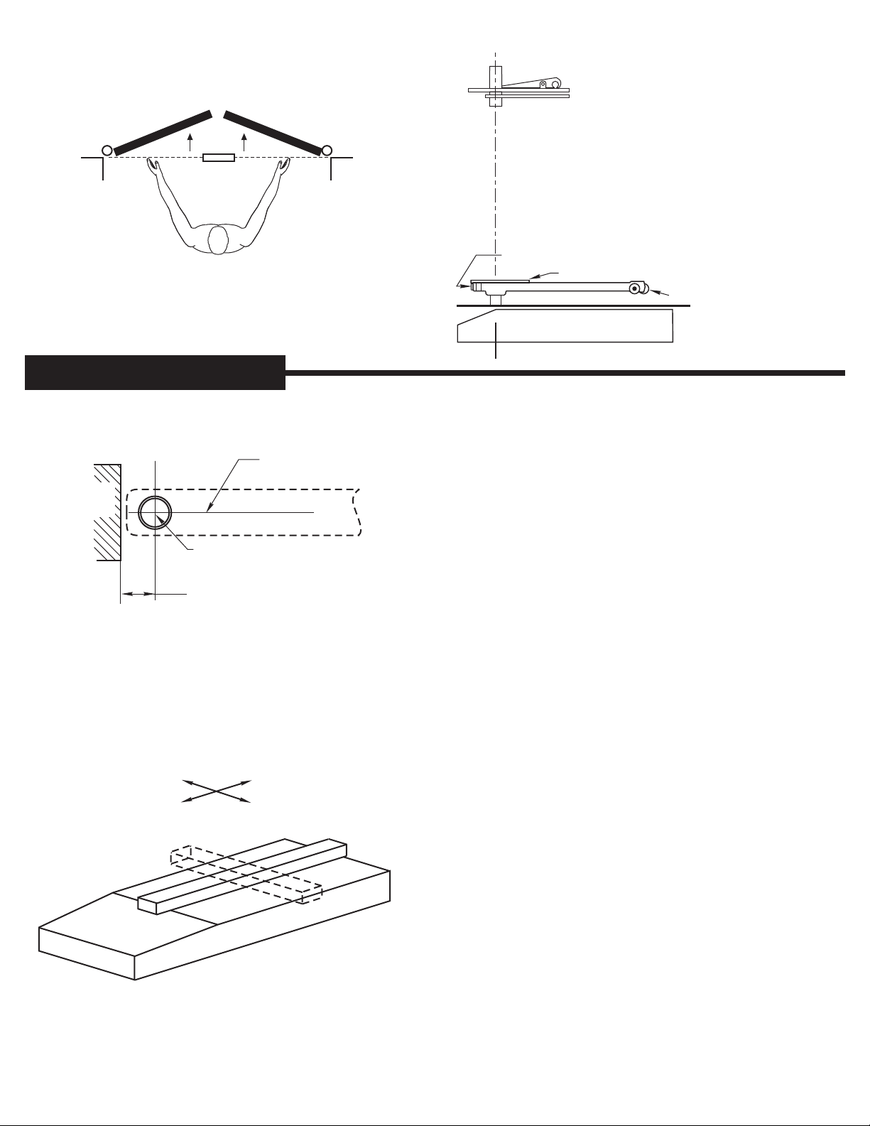
2. Install Cement Case in Floor
A. Cement case is set flush with finished floor.
B. Set cement case with closer in floor and block in position.
C. Case should be parallel with center line of door.
D. CEMENT CASE SHOULD BE LEVEL. Place levels per
Illustration.
E. Grout in cement case with closer. Cement should not get
between closer and case.
LEVEL IN BOTH
DIRECTIONS
A. Install top pivot in door per template.
B. Install top pivot in jamb per template.
C. Centerline of pivot pin should line up with centerline
of spindle. Use plumb line to assure accuracy. If
center lines don’t line up, loosen hold down screws
(4) and reposition closer. Tighten hold down screws
closest to spindle first. Then tighten screws at cylinder
end. Note: Closer must be lifted approx. 1/8” before
repositioning.
D. Mortise door for arm, arm plate H, and wood door
arm plate. Refer to template.
E. Drill two 5/8” dia. holes for arm alignment screws. Drill
3/8” hole at heel edge of door for adjusting screw.
F. Attach
arm alignment screws and washers to hold arm in
place.
Install arm, arm plate H, and shims if required.
4. Hang Door
CAUTION: Closer is shipped with "valve" screws down.
DO NOT FORCE VALVE DOWN.
A. Close both valve screws. NEVER FORCE VALVE
SCREW DOWN AS THIS WILL DAMAGE TIP
SEATING.
B. With arm on spindle, turn spindle until arm is in 30°
open position (see illustration).
C. Set door on spindle. DO NOT ATTEMPT TO CLOSE
DOOR.
D. Align two portions of top pivot and turn pin retracting
screw clockwise to engage top pivot pin.
E. Open door to 60° or more and turn valve screws
counterclockwise. Door will then close.
F. If necessary, turn adjusting screw at bottom of heel
edge of door to equalize side jamb clearances.
G. Adjust
center door in doorway.
arm alignment screws equally from each side
to
Rixson Specialty Door Controls Rixson Specialty Door Controls
Pin Retracting
Screw
Top Pivot
Pin
Centerline of Door
and Spindle
3. Install Top Pivot and Closer Arm
Centerline
of Door
DOOR
30°
Closer in
Floor
Alignment Screws
Adjusting Screw
Alignment Screws
Adjusting Screw
Spindle
Arm Plate “H”
Arm
Arm Plate “H”
866-474-9766 Technical Department
www.rixson.com
866-474-9766 Technical Department
www.rixson.com

PAGE 3
PAGE 2
How To Determine
Hand of Door
LH RH
Face a door swinging open away from you. If it opens to the
right, it is right hand. If it opens to the left, it is left hand.
Top Pivot Jamb Portion
Top Pivot Door Portion
IMPORTANT:
Use plumb line to make
sure that center line of
top pivot pin lines up
with center line of closer
spindle.
Installation Instructions
1. Locating Closer
Spindle Position
2-3/4” From Face of
Jamb to C of Spindle
L
Door
Jamb A. Measure 2-3/4” out from door jamb on centerline of door.
This is the location of the spindle center.
2. Install Cement Case in Floor
A. Cement case is set flush with finished floor.
B. Set cement case with closer in floor and block in position.
C. Case should be parallel with center line of door.
D. CEMENT CASE SHOULD BE LEVEL. Place levels per
Illustration.
E. Grout in cement case with closer. Cement should not get
between closer and case.
LEVEL IN BOTH
DIRECTIONS
A. Install top pivot in door per template.
B. Install top pivot in jamb per template.
C. Centerline of pivot pin should line up with centerline
of spindle. Use plumb line to assure accuracy. If
center lines don’t line up, loosen hold down screws
(4) and reposition closer. Tighten hold down screws
closest to spindle first. Then tighten screws at cylinder
end. Note: Closer must be lifted approx. 1/8” before
repositioning.
D. Mortise door for arm, arm plate H, and wood door
arm plate. Refer to template.
E. Drill two 5/8” dia. holes for arm alignment screws. Drill
3/8” hole at heel edge of door for adjusting screw.
F. Attach
arm alignment screws and washers to hold arm in
place.
Install arm, arm plate H, and shims if required.
4. Hang Door
CAUTION: Closer is shipped with "valve" screws down.
DO NOT FORCE VALVE DOWN.
A. Close both valve screws. NEVER FORCE VALVE
SCREW DOWN AS THIS WILL DAMAGE TIP
SEATING.
B. With arm on spindle, turn spindle until arm is in 30°
open position (see illustration).
C. Set door on spindle. DO NOT ATTEMPT TO CLOSE
DOOR.
D. Align two portions of top pivot and turn pin retracting
screw clockwise to engage top pivot pin.
E. Open door to 60° or more and turn valve screws
counterclockwise. Door will then close.
F. If necessary, turn adjusting screw at bottom of heel
edge of door to equalize side jamb clearances.
G. Adjust
center door in doorway.
arm alignment screws equally from each side
to
Rixson Specialty Door Controls Rixson Specialty Door Controls
Pin Retracting
Screw
Top Pivot
Pin
Centerline of Door
and Spindle
3. Install Top Pivot and Closer Arm
Centerline
of Door
DOOR
30°
Closer in
Floor
Alignment Screws
Adjusting Screw
Alignment Screws
Adjusting Screw
Spindle
Arm Plate “H”
Arm
Arm Plate “H”
866-474-9766 Technical Department
www.rixson.com
866-474-9766 Technical Department
www.rixson.com

Installation Instructions
50 (06-09)
50 Floor Closer
Center Hung
Single or Double Acting
Non-Handed
Closing speeds can be adjusted to suit local conditions and
requirements. Label on closer face designates the purpose
of each adjustment screw. Adjustments are for speed
control.
A. The stroke valve allows adjustment from open to 15°.
B. The latch valve allows adjustment from 15° to closed
position.
C. IMPORTANT: Back check valve option must be adjusted
to vary resistance from light to firm at 70° of door
opening.
D. The delay valve option allows closing speed adjustment
from o en position to 65°.p
Repairs, parts replacement or internal adjustments must be done by a Rixson authorized repair agency. Consult www.rixson.com
for an authorized repair agency in your area.
Closer Adjustment
Conversion from inches to metric: inch x 25.4.
Template
PAGE 4
Rixson Specialty Door Controls 866-474-9766 Technical Department
www.rixson.com
Rixson Specialty Door Controls 866-474-9766 Technical Department
www.rixson.com
FS
LATCH FS
STROKE
FS
DELAY
+-
BACK
CHECK
1/4-20 x 5/8" FHMS or
#14 x 1/2" FHWS
15/32
1-15/32 6-3/4
JAMB PORTION 9/32
9/32
1-5/16
21/32
9/32
12-24 x 5/8" FHMS or
#12 x 1-1/4" FHWS
(2 Places)
DOOR PORTION
5/8
5/8
1-1/8
4-13/16
5-9/32
1-1/4
1/4-20 x 5/8" FHMS or
#14 x 1-1/2" FHWS
(2 Places)
See
Note 4 Tighten Spindle
Screw Firmly
Arm
Spindle
Washer
Spindle
Adapter
Set Cement Case Flush
with Finished Floor
See Note 5
WITH THRESHOLD
Threshold
3/16
Door Mortised
Deep for Arm
B
A
1/4 Threshold
1/2 Threshold
A B
1-13/16
1-9/16
1-1/8
7/8
See Note 5
340 TOP PIVOT
Pivot Shown Engaged
Finish Plate
7/8 Dia.
1-1/4 Dia.
1-1/32
1-7/16
1/8
3/4
1/4
9/16
2-5/8
2-3/4
1/16
9/32
Arm Floor Plate
Jamb
2-5/8 R.
Max.
19-1/4
4-1/2
C
LSpindle
2
19-1/8
Fasten Front
Mounting
Screws First Cement Case
2-3/4
Arm Plate
7/16
3/16
1/8 2-5/8
10-3/4
7-7/16
Provide
3/8” Dia.
Hole
With Threshold
Use Top (2) Holes With Floor Plate
Use Bottom
(2) Holes
1-9/16
1-1/16
(11/16 w/
Threshold)
C
LSpindle
ARM PLATE H
3/16
1-25/32 1-7/32
1-1/4
1-19/32 1-13/32
2-3/32
3-13/16
11/32
5/8
29/32
1/4-20 x 1” FHMS
or #14 x 2” FWHS
(4 Places)
WITH FLOOR PLATE
Set Cement Case Flush
with Finished Floor
Cement Case
Floor
Plate
Door Mortised
1-9/16” Deep
for Arm
3/16
4-3/8
7/8
1-3/8” Min. Clearance
Required for Arm, Arm
Plate H and Shims
Notes:
1. Do not scale drawing.
2. Suitable reinforcing by others.
3. Rixson design threshold available on
request.
4. Tighten adjusting screw to notched “V”
line on arm to acquire standard initial
location of door. Screw moves door
towards and away from jamb to equalize
door clearances.
5. Provide 5/8” dia. holes for alignment
screws (2 places).
6. Do not remove grind plate until closer is
installed.
7. External stop by others required.
8. All dimensions given in inches.
ASSA ABLOY
RIXSON®
Rixson® is a registered trademark of Yale Security Inc., an ASSA ABLOY Group company. Copyright© 2005, 2009, Yale Security Inc., an ASSA ABLOY Group company.
All rights reserved. Reproduction in whole or in part without the express written permission of Yale Security Inc. is prohibited.
ASSA ABLOY
RIXSON®

Installation Instructions
50W (06-09)
W50 Floor Closer
Center Hung
Single or Double Acting
Non-Handed
Wood Door Installation
Closing speeds can be adjusted to suit local conditions and
requirements. Label on closer face designates the purpose
of each adjustment screw. Adjustments are for speed
control.
A. The stroke valve allows adjustment from open to 15°.
B. The latch valve allows adjustment from 15° to closed
position.
C. IMPORTANT: Back check valve option must be adjusted
to vary resistance from light to firm at 70° of door
opening.
D. The delay valve option allows closing speed adjustment
from open position to 65°.
Repairs, parts replacement or internal adjustments must be done by a Rixson authorized repair agency. Consult www.rixson.com
for an authorized repair agency in your area.
Closer Adjustment
Conversion from inches to metric: inch x 25.4.
Template
PAGE 4
Rixson Specialty Door ControlsRixson Specialty Door Controls
Notes:
1. Do not scale drawing.
2. Suitable reinforcing by others.
3. Rixson design threshold available on request.
4. Tighten adjusting screw to notched “V” line
on arm to acquire standard initial location
of door. Screw moves door towards and
away from jamb to equalize door clearances.
5. Auxiliary stop required.
6. All dimensions given in inches.
TOP PIVOT
Finish Plate
7/8 Dia.
1-1/4 Dia.
1-1/32
1-7/16
1/8
3/4
1/4
9/16
2-5/8
2-3/4
1/16
9/32
1/4-20 x 5/8" FHMS or
#14 x 1/2" FHWS
15/32
1-15/32 6-3/4
JAMB PORTION 9/32
9/32
1-5/16
21/32
9/32
12-24 x 5/8" FHMS or
#12 x 1-1/4" FHWS
(2 Places)
DOOR PORTION
5/8
5/8
1-1/8
4-13/16
5-9/32
1-1/4
1/4-20 x 5/8" FHMS or
#14 x 1-1/2" FHWS
(2 Places)
Arm Floor Plate
Jamb
2-5/8 R.
Max.
19-1/4
4-1/2
C
LSpindle
2
19-1/8
Fasten Front
Mounting
Screws First Cement Case
2-3/4
Spindle Shoulder Collar
Arm Plate
Shim
Wood Door
Arm Plate
7/16
3/16
1/8 2-5/8 9*
2-1/4* 7-7/16 *Mortised
Provide
3/8” Dia.
Hole
Use Top
(2) Holes
See
Note 4 Tighten Spindle
Screw Firmly
Arm
Spindle
C
LDoor
C
LSpindle
WOOD DOOR ARM PLATE
10-1/2
6-7/32
1-19/32
1-13/32
11/16
1-3/8
9/32
9/16
2-3/32
1-25/32
4-7/32
1-7/32
#14 x 2-1/2” FWHS
(6 Places)
WITH FLOOR PLATE
Set Cement Case Flush
with Finished Floor
Cement Case
Floor
Plate
Door Mortised
1-7/8” Deep
for Arm
3/16
4-3/8
1-1/4
Provide 9/16
Dia. Hole for
Alignment
Screw
(2 Places)
1-3/8” Min. Clearance
Required for Arm, Arm
Plate H and Shims
WITH THRESHOLD
Set Cement Case Flush
with Finished Floor
Threshold
3/16
Door Mortised
Deep for Arm
Provide 9/16
Dia. Hole for
Alignment
Screw
(2 Places)
BA
1/4 Threshold
1/2 Threshold
A B
1-3/4
1-1/2
1-1/8
7/8
FS
LATCH FS
STROKE
FS
DELAY
+-
BACK
CHECK
866-474-9766 Technical Department
www.rixson.com
866-474-9766 Technical Department
www.rixson.com
ASSA ABLOY
RIXSON®
Rixson® is a registered trademark of Yale Security Inc., an ASSA ABLOY Group company. Copyright© 2005, 2009, Yale Security Inc., an ASSA ABLOY Group company.
All rights reserved. Reproduction in whole or in part without the express written permission of Yale Security Inc. is prohibited.
ASSA ABLOY
RIXSON®

PAGE 3
PAGE 2
How To Determine
Hand of Door
LH RH
Face a door swinging open away from you. If it opens to the
right, it is right hand. If it opens to the left, it is left hand.
Top Pivot Jamb Portion
Top Pivot Door Portion
IMPORTANT:
Use plumb line to make
sure that center line of
top pivot pin lines up
with center line of closer
spindle.
Installation Instructions
1. Locating Closer
Spindle Position
2-3/4” From Face of
Jamb to C of Spindle
L
Door
Jamb A. Measure 2-3/4” out from door jamb on centerline of door.
This is the location of the spindle center.
2. Install Cement Case in Floor
A. Cement case is set flush with finished floor.
B. Set cement case in floor and block in position.
C. Case should be parallel with center line of door.
D. CEMENT CASE SHOULD BE LEVEL. Place levels per
Illustration.
E. Grout in cement case with closer. Cement should not get
between closer and case.
LEVEL IN BOTH
DIRECTIONS
A. Install top pivot in door per template.
B. Install top pivot in jamb per template.
C. Centerline of pivot pin should line up with centerline
of spindle. Use plumb line to assure accuracy. If
center lines don’t line up, loosen hold down screws
(4) and reposition closer. Tighten hold down screws
closest to spindle first. Then tighten screws at cylinder
end. Note: Closer must be lifted approx. 1/8” before
repositioning.
D. Mortise door for arm, arm plate H, and wood door
arm plate. Refer to template.
E. Drill two 9/16” dia. holes for arm alignment screws.
Drill 3/8” hole at heel edge of door for adjusting screw.
F. Attach arm to spindle using spindle screw supplied
and tighten securely. Install arm plate H, wood door
arm plate, and shim.
4. Hang Door
CAUTION: Closer is shipped with "valve" screws down.
DO NOT FORCE VALVE DOWN.
A. Close both valve screws. NEVER FORCE VALVE
SCREW DOWN AS THIS WILL DAMAGE TIP
SEATING.
B. With arm on spindle, turn spindle until arm is in 30°
open position (see illustration).
C. Set door on spindle. DO NOT ATTEMPT TO CLOSE
DOOR.
D. Align two portions of top pivot and turn pin retracting
screw clockwise to engage top pivot pin.
E. Open door to 60° or more and turn valve screws
counterclockwise. Door will then close.
F. If necessary, turn adjusting screw at bottom of heel
edge of door to equalize side jamb clearances.
G. Adjust
center door in doorway.
arm alignment screws equally from each side
to
Rixson Specialty Door Controls Rixson Specialty Door Controls
Pin Retracting
Screw
Top Pivot
Pin
Centerline of Door
and Spindle
3. Install Top Pivot and Closer Arm
Centerline
of Door
DOOR
30°
Closer in
Floor
Alignment Screws
Adjusting Screw
Alignment Screws
Arm Plate “H”
Adjusting Screw
Shim
Wood Door Arm Plate
Spindle
Shim
Arm Plate “H”
Wood Door Arm Plate
Arm
Arm Plate “H”
866-474-9766 Technical Department
www.rixson.com
866-474-9766 Technical Department
www.rixson.com

Installation Instructions
50W (06-09)
W50 Floor Closer
Center Hung
Single or Double Acting
Non-Handed
Wood Door Installation
Closing speeds can be adjusted to suit local conditions and
requirements. Label on closer face designates the purpose
of each adjustment screw. Adjustments are for speed
control.
A. The stroke valve allows adjustment from open to 15°.
B. The latch valve allows adjustment from 15° to closed
position.
C. IMPORTANT: Back check valve option must be adjusted
to vary resistance from light to firm at 70° of door
opening.
D. The delay valve option allows closing speed adjustment
from open position to 65°.
Repairs, parts replacement or internal adjustments must be done by a Rixson authorized repair agency. Consult www.rixson.com
for an authorized repair agency in your area.
Closer Adjustment
Conversion from inches to metric: inch x 25.4.
Template
PAGE 4
Rixson Specialty Door ControlsRixson Specialty Door Controls
Notes:
1. Do not scale drawing.
2. Suitable reinforcing by others.
3. Rixson design threshold available on request.
4. Tighten adjusting screw to notched “V” line
on arm to acquire standard initial location
of door. Screw moves door towards and
away from jamb to equalize door clearances.
5. Auxiliary stop required.
6. All dimensions given in inches.
TOP PIVOT
Finish Plate
7/8 Dia.
1-1/4 Dia.
1-1/32
1-7/16
1/8
3/4
1/4
9/16
2-5/8
2-3/4
1/16
9/32
1/4-20 x 5/8" FHMS or
#14 x 1/2" FHWS
15/32
1-15/32 6-3/4
JAMB PORTION 9/32
9/32
1-5/16
21/32
9/32
12-24 x 5/8" FHMS or
#12 x 1-1/4" FHWS
(2 Places)
DOOR PORTION
5/8
5/8
1-1/8
4-13/16
5-9/32
1-1/4
1/4-20 x 5/8" FHMS or
#14 x 1-1/2" FHWS
(2 Places)
Arm Floor Plate
Jamb
2-5/8 R.
Max.
19-1/4
4-1/2
C
LSpindle
2
19-1/8
Fasten Front
Mounting
Screws First Cement Case
2-3/4
Spindle Shoulder Collar
Arm Plate
Shim
Wood Door
Arm Plate
7/16
3/16
1/8 2-5/8 9*
2-1/4* 7-7/16 *Mortised
Provide
3/8” Dia.
Hole
Use Top
(2) Holes
See
Note 4 Tighten Spindle
Screw Firmly
Arm
Spindle
C
LDoor
C
LSpindle
WOOD DOOR ARM PLATE
10-1/2
6-7/32
1-19/32
1-13/32
11/16
1-3/8
9/32
9/16
2-3/32
1-25/32
4-7/32
1-7/32
#14 x 2-1/2” FWHS
(6 Places)
WITH FLOOR PLATE
Set Cement Case Flush
with Finished Floor
Cement Case
Floor
Plate
Door Mortised
1-7/8” Deep
for Arm
3/16
4-3/8
1-1/4
Provide 9/16
Dia. Hole for
Alignment
Screw
(2 Places)
1-3/8” Min. Clearance
Required for Arm, Arm
Plate H and Shims
WITH THRESHOLD
Set Cement Case Flush
with Finished Floor
Threshold
3/16
Door Mortised
Deep for Arm
Provide 9/16
Dia. Hole for
Alignment
Screw
(2 Places)
BA
1/4 Threshold
1/2 Threshold
A B
1-3/4
1-1/2
1-1/8
7/8
FS
LATCH FS
STROKE
FS
DELAY
+-
BACK
CHECK
866-474-9766 Technical Department
www.rixson.com
866-474-9766 Technical Department
www.rixson.com
ASSA ABLOY
RIXSON®
Rixson® is a registered trademark of Yale Security Inc., an ASSA ABLOY Group company. Copyright© 2005, 2009, Yale Security Inc., an ASSA ABLOY Group company.
All rights reserved. Reproduction in whole or in part without the express written permission of Yale Security Inc. is prohibited.
ASSA ABLOY
RIXSON®
Table of contents
Other Rixson Door Opening System manuals


Popular Door Opening System manuals by other brands


Johnson Controls
Johnson Controls MC-302E PG+ installation guide

Bohle
Bohle SmartClose manual

Roger Technology
Roger Technology H70/104AC Instruction and warnings for the installer

DITEC
DITEC OLLY C Installation and maintenance manual

Assa Abloy
Assa Abloy SARGENT 351 installation instructions

BFT
BFT SUB EL manual


