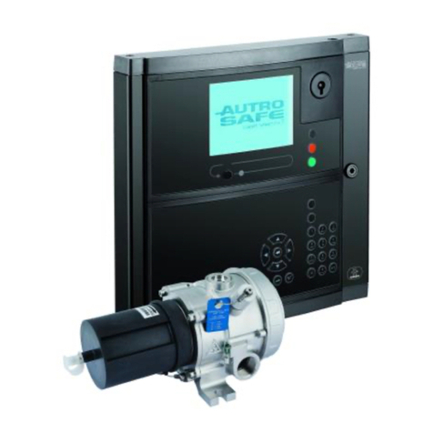
Autronica AutroVoice miniVES Series User manual

Service Manual
AutroVoice miniVES
Service Manual, AutroVoice miniVES, 116-P-AutroVoiceminiVES/DGB, 2018-06-21
Ref. miniVES_manual_en, Rev. 1.2017

2
COMPACT VOICE ALARM SYSTEM
SERVICE MANUAL

3
Table of Contents
1. Autronica Fire and Security presentation ___________________________________________________________________ 11
2. AutroVoice miniVES system presentation___________________________________________________________________ 12
3. Symbols used in the document ______________________________________________________________________________ 14
4. Warranty conditions _________________________________________________________________________________________ 15
5. Requirements ________________________________________________________________________________________________ 16
5.1 Unpacking ________________________________________________________________________________________________ 16
5.2 Installation requirements ___________________________________________________________________________________ 17
5.3 Environmental conditions __________________________________________________________________________________ 17
6. Device description ___________________________________________________________________________________________ 18
6.1 Internal devices____________________________________________________________________________________________ 18
6.1.1 Control units _______________________________________________________________________________________ 18
6.1.1.1 AutroVoice miniVES series 2001, 4001 and 4002 units__________________________________________ 19
6.1.1.2 AutroVoice miniVES series 2001N, 4001N, 4002N _____________________________________________ 21
6.1.1.3 AutroVoice miniVES series 2001L, 4001L and 4002L units ______________________________________25
6.1.1.4 AutroVoice miniVES series 2001LN, 4001LN, 4002LN __________________________________________ 26
6.1.1.5 DFMS Box _________________________________________________________________________________29
6.1.2 Extension cards_____________________________________________________________________________________30
6.1.2.1 ABT-xNET_mini-1Gb/WAN/RS communication card ___________________________________________30
6.1.2.2 ABT-xNet_mini-1Gb communication card ____________________________________________________ 32
6.1.2.3 ABT-xCtrLine-4 – Control card of 4 loudspeaker lines __________________________________________ 34
6.1.2.4 ABT-xCtrLine-2 – 2 loudspeaker lines control card _____________________________________________36
6.1.3 Built in amplier modules ___________________________________________________________________________ 39
6.1.3.1 Technical details ___________________________________________________________________________ 39
6.1.4 AutroVoice miniVES charger _________________________________________________________________________40
6.2 External devices ___________________________________________________________________________________________ 42
6.2.1 ABT-DFMS reman microphone______________________________________________________________________ 42
6.2.2 ABT-DMS zone microphone _________________________________________________________________________46
6.2.3 ABT-DMS-LCD – zone microphone with LCD __________________________________________________________ 49
6.2.4 ABT-EKB-20M – microphone keyboard extension______________________________________________________ 52
6.2.4.1 Functional buttons performance ____________________________________________________________ 53
6.2.4.2 Functional buttons signaling________________________________________________________________ 53
6.2.5 ABT-M01 Microphone _______________________________________________________________________________54
7. System hardware installation________________________________________________________________________________ 56
7.1 Information on limiting damage consequences ______________________________________________________________ 56
7.2 General connection diagram________________________________________________________________________________56
7.3 Connecting devices ________________________________________________________________________________________ 57
7.3.1 Control units _______________________________________________________________________________________ 58
7.3.1.1 Daisy Chain Topology ______________________________________________________________________58
7.3.1.2 Ring Topology _____________________________________________________________________________ 59

4
COMPACT VOICE ALARM SYSTEM
SERVICE MANUAL
7.3.2 Batteries ___________________________________________________________________________________________60
7.3.3 Microphones ______________________________________________________________________________________ 62
7.3.3.1 Fireman microphone RING-type optic ber connection _______________________________________ 62
7.3.3.2 Fireman microphone CHAIN-type cable connection __________________________________________63
7.3.3.3 Dierent ways to power the reman microphone_____________________________________________ 63
7.3.3.4 Zone microphones – types of connection ____________________________________________________65
7.3.3.5 Connecting power to zone microphones_____________________________________________________ 67
7.4 Preparing sound system for VAS application _________________________________________________________________68
8. Operation modes – LED colors ______________________________________________________________________________ 70
8.1 Normal mode _____________________________________________________________________________________________ 72
8.2 Alarm mode _______________________________________________________________________________________________ 72
8.3 Failure mode ______________________________________________________________________________________________ 72
8.4 Lock mode ________________________________________________________________________________________________72
9. Instruction for performing tests and trials__________________________________________________________________73
9.1 Instructions for performing basic functions __________________________________________________________________73
9.1.1 Alarm mode________________________________________________________________________________________73
9.1.2 Failure mode _______________________________________________________________________________________ 74
9.1.3 Controlling backup power batteries __________________________________________________________________ 74
9.2 Testing the system _________________________________________________________________________________________ 75
10. Operation instructions_______________________________________________________________________________________ 76
10.1 Control Unit _______________________________________________________________________________________________ 76
10.2 Fireman microphone_______________________________________________________________________________________ 76
10.3 Zone microphone__________________________________________________________________________________________ 78
11. Maintenance and service ____________________________________________________________________________________ 79
11.1 Preparations before VAS system maintenance works__________________________________________________________ 79
11.1.1 Initial procedures for system testing__________________________________________________________________ 79
11.1.2 System testing _____________________________________________________________________________________ 79
11.2 System maintenance _______________________________________________________________________________________ 81
11.2.1 Daily review ________________________________________________________________________________________ 81
11.2.2 Inspection every 6 months __________________________________________________________________________ 81
11.2.3 Annual inspection __________________________________________________________________________________83
11.2.4 Manufactures remarks ______________________________________________________________________________83
12. Conguration Software ______________________________________________________________________________________84
12.1 Welcome screen ___________________________________________________________________________________________84
12.2 Basic Conguration ________________________________________________________________________________________ 85
12.3 System Conguration ______________________________________________________________________________________ 87
12.3.1 File ________________________________________________________________________________________________88
12.3.2 Preferences ________________________________________________________________________________________ 89
12.3.3 System_____________________________________________________________________________________________90
12.3.4 System Connection Settings _________________________________________________________________________ 92
12.3.5 Workspace _________________________________________________________________________________________ 93
12.3.6 Central Unit Conguration___________________________________________________________________________94

5
12.3.7 DFMS ____________________________________________________________________________________________100
12.3.8 DMS ______________________________________________________________________________________________103
12.3.9 DMS-LCD _________________________________________________________________________________________105
12.3.10 xCtrLine-2 / 4 ______________________________________________________________________________________106
12.4 Priority Manager Conguration ____________________________________________________________________________107
12.5 Group Zone Conguration_________________________________________________________________________________109
12.6 Control I/O Conguration__________________________________________________________________________________ 110
12.6.1 Group Logical Inputs_______________________________________________________________________________ 110
12.6.2 Group Logical Outputs _____________________________________________________________________________ 111
12.6.3 Timers ____________________________________________________________________________________________ 113
12.7 Matrix Conguration ______________________________________________________________________________________ 114
12.8 Scenario Conguration ____________________________________________________________________________________ 116
12.9 Event Conguration_______________________________________________________________________________________ 118
12.9.1 Functions _________________________________________________________________________________________120
12.10 Reports __________________________________________________________________________________________________125
12.11 Basic steps required to program the system _________________________________________________________________126
12.12 Glossary _________________________________________________________________________________________________ 127
12.13 FAQ______________________________________________________________________________________________________ 128
12.14 Appendix ________________________________________________________________________________________________130
13. Manual touch-screen system _______________________________________________________________________________ 138
13.1 Fire zones ________________________________________________________________________________________________ 139
13. 2 Service ___________________________________________________________________________________________________ 141
13.3 Fault register _____________________________________________________________________________________________144
13.4 Interface settings _________________________________________________________________________________________ 145
14. Annexes______________________________________________________________________________________________________146
15. Certicates __________________________________________________________________________________________________ 147
16. Glossary______________________________________________________________________________________________________148
17. List of tables _________________________________________________________________________________________________ 149
18. List of drawings______________________________________________________________________________________________150
Notes ____________________________________________________________________________________________________________ 152

6
COMPACT VOICE ALARM SYSTEM
SERVICE MANUAL

7
NOTE!
The manufacturer reserves a right to modify parameters and methods of operation without further notice. By virtue ofregular
modications and improvements, certain functions specied in this manual may dier insignicantly.
In order to avoid diculties in operating the Voice Alarm System, it is advisable to get familiar with the manual before the rst use.
VAS central unit is equipped with a set of automatic functions responsible for testing the system performance. The central unit
uses FAILURE LED to signal irregularities. In such case, it is necessary to react immediately and, if necessary, consult a person in
charge of VAS performance.
Exposing devices to extreme temperature, direct sunlight, moisture or dust may result in a re or electric shock.
c Do not connect the device to the source of power before all installation works have been completed.
c Read this manual.
c Keep this manual.
c Pay special attention to warnings.
c Follow all provisions of this manual.
c Avoid contact with water. Do not let the device come in contact with water or other liquids.
c Use devices with utmost care.
c Use soft materials to clean devices. Never use solvents, such as petrol or diluent.
c Do not cover vent openings in device casing. Install the device in accordance with the manufacturer’s instructions.
c Do not install the device close to sources of heat.
c Protect the feeder cable against stepping, pressure, bending or crushing, particularly close to plugs, sockets and
the area on the device casing which is connected to the wire. A damaged Power Cord poses re or electric shock
hazards. Never touch electric plugs with wet palms.
c Avoid mechanical shocks. Strong impact and shocks may damage the equipment.
c Be careful while grabbing wires. To connect and disconnect all wires, grab a plug, not a wire.
c
Always switch o power before disconnecting other devices. To avoid device and accessories damage, switch o the
power supply by using the master switch of the device before connecting or disconnecting wires. While connecting
wires, pay special attention to their polarization. A change of poles may damage them.
c Use accessories and additional parts specied by the manufacturer only.
c Do not leave any redundant items in the device.
c
Do not try to repair or modify the device on your own. The device is not equipped with elements intended
tobeserviced by the user. As for maintenance, contact the authorized service provider.
c The warranty becomes invalid if you open or manipulate internal subassemblies on your own.
c Service works are required if any type of system damage occurs.
c
The workers operating in the area where the system was installed should complete a suitable training with regard to
system operation. One person must be responsible for maintaining proper performance and system maintenance.
c
Following the regulations, the system must be maintained on a yearly basis, while the manufacturer advises
tomaintain the system twice a year.

8
COMPACT VOICE ALARM SYSTEM
SERVICE MANUAL
AUTROVOICE MINIIVES
DECLARATION OF PERFORMANCE
www.autronicare.com
1. Product Emergency Sound System
2. Type of construction product
AutroVoice miniVES
Components:
miniVES 2001 / miniVES 2001L / miniVES 2001N / miniVES 2001LN /
miniVES 4001 / miniVES 4001L / miniVES 4001N / miniVES 4001LN /
miniVES 4002 / miniVES 4002L / miniVES 4002N / miniVES 4002LN /
DFMS BOX / DFMS BOX-L /
ABT-xNET_MINI-1Gb/WAN/RS / ABT-xNET_MINI-1Gb/WAN /
ABT-xCtrLine-2 / ABT-xCtrLine-4 /
SF-MM31002D-GP / SF-CP100C-GP / SFP-1GBT-06 /
SF-MM31/55WD055D-GP / SF-MM31/55WD055-GP /
SF-MMS31/55WD055D-GP / SF-MMS31/55WD055-GP/
SF-SM31/55WD020D-GP / SF-SM31/55WD020-GP /
SF-SMS31/55WD020D-GP / SF-SMS31/55WD020-GP /
ABT-DFMS / ABT-EKB-20M / GUI ABT-xLCD / ABT-REG1 /
ST-POE8P-A / ST-POE4P-A / ST-POE16P-AF / ST-POE1R-P /
ST-I2POESFP / ST-I4POESFP /
Netgear FS116P / FS116Pv2 / FS108P
3. Type, batch or serial numer or any other element
allowingidentication of the construction product See CE mark label and marking on boards
4. Declared intended use of product Fire Safety
5. Manufacturer Ambient-System Sp. z o.o.
ul. Galaktyczna 37, 80-299 Gdańsk, Polska
6. System of AVCP 1
7. Notied body CNBOP-PIB 1438-CPR-0527
No AutroVoice miniVES-XXXXXXXX
Declaration of Performance

9
Example of VASCU AutroVoice miniVES rating plate
Certificate of constancy of performance EN 54-4, EN 54-16 1438-CPR-XXXX
Certificate of admission CNBOP-PIB 2909/2017
Declaration of Performance EST20180314
Declared intended use of product fire safety
Comply with EN 54-4 / EN 54-16
Ingress Protection Rating 30
AutroVoice miniVES 2001LN
Manufacturer:
Autronica Fire and Security
Bromstadveien 59, 7047
Trondheim, Norway
SN
18

10
COMPACT VOICE ALARM SYSTEM
SERVICE MANUAL
Impact on the environment
This product was marked in accordance with WEEE Directive (2002/96/EC) and further amendments on waste
electrical and electronic equipment. Assuring a proper scrapping, you contribute to reduction of risk of negative
impact on the environment and people’s health, which would occur in the case of improper equipment disposal.
The symbol located on the product or attached documents means that our product has not been classied as
domestic waste. The equipment must be transported to a suitable waste treatment plant in order to recycle it.
To see more details about recycling our product, contact a local authority representative, waste treatment
service provider or the store where our product was sold. Pursuant to the act of 29 July 2005 on waste electronic and electrical
equipment, it is forbidden to dispose of the waste electronics along with other (municipal) waste because such actions entail
criminal penalties. Packaging elements were made of cardboard and polyethylene foam. For this reason, they may be subject to
recycling. In so doing, redundant packaging must be sorted out in accordance with their intended use and delivered to
the local waste collector.
In the interest of protecting human's health and environment, we assure that our products, subject to RoHS 2011/65/EU directive
provisions on the use of hazardous substances in electric and electronic equipment, have been designed and manufactured in
accordance with requirements of this directive.

11
1. Autronica Fire and Security presentation
Autronica Fire and Security is a leading innovator, manufacturer and supplier of re and gas safety worldwide.
Owned by United Technologies Corporation (UTC), we employ almost 500 people handling the complete value chain, from idea,
development and manufacturing to the marketing, sales and servicing of our products.
Our products ensure safety in applications on land, sea and in the petrochemical, oil and gas sectors, and include:
» Fire detection systems
» Integrated re and gas detection systems
» Voice alarm systems
» Emergency light systems
» Presentation systems
» Integrated safety and emergency management systems
» Video solutions
» Fire suppression systems
We are an international company with oces worldwide and our HQ is located in Trondheim, Norway’s technology hotspot.
For more information on solutions and products, please refer to our ocial website www.autronicare.com
Autronica Fire and Security
Protecting life, environment and property

12
COMPACT VOICE ALARM SYSTEM
SERVICE MANUAL
2. AutroVoice miniVES system presentation
AutroVoice miniVES is the latest product promoted by Autronica Fire and Security, the company specializing in production of
reliable and certied voice alarm systems. AutroVoice miniVES is a Public Address & Voice Evacuation system based on optical
ber digital transmission of voice, alarm and commercial messages.
AutroVoice miniVES VAS central unit has been designed in accordance with the European EN 54-16 norm.
In accordance with the internal regulations of CEN/CENELEC, the organizations for standardization of the following countries are
obligated to introduce this European standard:
Austria, Belgium, Bulgaria, Cyprus, the Czech Republic, Denmark, Estonia, Finland, France, Germany, Greece, Hungary, Island,
Ireland, Italy, Lithuania, Latvia, Luxembourg, Malta, the Netherlands, Norway, Poland, Portugal, Romania, Spain, Slovakia, Slovenia,
Sweden, Switzerland and Great Britain.
AutroVoice miniVES system includes the following: control devices, reman microphone panels and zone microphones. All com-
ponents are certied (ocially approved). The system rests on a modern platform which allows a digital scalable communication
between all elements of the system, as well as between other integrated safety systems.
AutroVoice miniVES system has been developed with various applications in mind – it is perfect for both decentralized
and centralized systems.
The system architecture is based on optical connection between control unit devices and other system elements. It allows creation
of highly large facilities, such as airport terminals, oil elds and reneries, shopping centers or oce complexes.
At the same time, along with the customized construction of control unit and network types, we are able to create compact
systems for single small and middle-sized facilities, as well as larger groups connected by a digital network.
The following components account for integrated concept of AutroVoice miniVES system VAS central unit:
AutroVoice miniVES 2001 unit
AutroVoice miniVES 2001N unit
AutroVoice miniVES 2001L unit
AutroVoice miniVES 2001LN unit
AutroVoice miniVES 4001 unit
AutroVoice miniVES 4001N unit
AutroVoice miniVES 4001L unit
AutroVoice miniVES 4001LN unit
AutroVoice miniVES 4002 unit
AutroVoice miniVES 4002N unit
AutroVoice miniVES 4002L unit
AutroVoice miniVES 4002LN unit
DFMS Box unit

13
4 loudspeaker line control card ABT-xCtrLine-4
2 loudspeaker line control card ABT-xCtrLine-2
ABT-DFMS reman microphone
ABT-DMS zone microphone
ABT-DMS-LCD zone microphone with display
ABT-EKB-20M microphone keyboard extension
Optional features in accordance with EN 54-16 standard:
Sound signaling X
Delayed voice alarm introduction W
Gradual evacuation W
Manual voice alarm muting W
Manual voice alarm cancelling W
Fire alarm device outputs W
Voice alarm output W
Signaling damage related to transmission track to FACIE W
Signaling damage related to voice alarm zones W
Lock status W
Manual control of voice alarm W
Digital interface between VASCU and external control devices W
Emergency microphones W
Back-up power amplier W

14
COMPACT VOICE ALARM SYSTEM
SERVICE MANUAL
3. Symbols used in the document
Warning!
This symbol means a potentially hazardous situation posing a death or disability hazards
Attention!
This symbol means potentially hazardous situation posing medium or minor injuries
and/or material loss hazards.
Warning!
This symbol means that using the above-mentioned products increases
therisk of visual impairment.

15
4. Warranty conditions
Warranty conditions are part of General Terms & Conditions of Delivery available at www.autronicare.com
1.

16
COMPACT VOICE ALARM SYSTEM
SERVICE MANUAL
5. Requirements
Unused devices must be stored in the original packaging, in enclosed rooms with the ambient temperature ranging from -20°C
to 70°C and relative humidity – from 5% to 95% (without condensation).
Once the device has been moved from cold to warm environment, there is a risk of water condensation, which has a negative
impact on device performance. In such case, it is necessary to leave the device to let it adapt to a new surrounding for about an
hour before the operation.
During the transport, the devices should be packed in a way assuring reduced risk of mechanical damage and
impact of weather conditions.
c AutroVoice miniVES should only be transported vertically, as indicated on the carton of the device;
c
AutroVoice miniVES should be transported only on a transport pallet (wooden or plastic) up to 3 stacking units.
Additional load stabilization methods such as plastic stretch wrap, shrink wrap, plastic or stretch tape is required
for additional securement.
3
PN: 10P000ABT00059
AV miniVES 2001
Compact Voice Evacuation System
22,9 kg
5.1 Unpacking
Pleasereadthisservice manualto get familiar withrelevantdetailsconcerning installation,operation,nature andproduct functions.
If it is necessary to return the product to the service point, wrap the device into the original packaging (or identical
to the origintal one).

17
5.2 Installation requirements
The alarm central unit room, in which VASCU is located, must satisfy the following conditions:
»
Fire protection device operation room (FPDOR) should be located on the oor of the structure, close to entrance/exit
designed and marked as the entrance for rescue teams.
» The room must be located and marked in a way that allows rescuers to notice it at the entrance. It is advisable to make sure
FPDOR access doors are not located farther than 10m from rescue team exit.
» The width of passage leading to the room should be at least 1,5m.
» The room should be properly marked.
»
If FPDOR is located at a distance greater than 10m from the rescue team exit, additional signs must be used in order to point
location and direction to FPDOR.
» The Fire Safety Instructions in graphics and site evacuation procedures should include signs and location of FPDOR.
» Install the Manual Call Point in FPDOR or in its immediate vicinity. FPDOR should be monitored by automatic sensors being
part of re alarm system on the site.
» Access to FPDOR should be given solely to authorized persons and rescue team. It is acceptable to lock the door as long as
one key is located in a suitably marked box with breakable glass attached to the wall in immediate vicinity to room doors.
» FPDOR should be a closed room whose walls and ceilings have REI 60 re resistance rating. The door of FPDOR should have
EI30 re resistance rating.
»
The control desk with a reman microphone should be connected to VASCU via wires assuring circuit continuity in case of re.
» Natural and articial lighting should be provided. Lighting intensity in the room must be min. 500 lx.
» The room must be equipped with emergency lighting of an average lighting intensity – min. 10 lx.
»
Weather conditions must satisfy the following requirements: temperature from 0°C to +40°C, relative humidity from
25%to80%, air pressure from 860 hPa to 1060 hPa.
» A suitable amount of space around front VASCU board must be provided in order to allow required manipulations.
» The height of control and indication devices assembly should allow their suitable operation.
»
Background noisevalues in the room, in which the console with the reman microphone is located, should not exceed 40dB.
» A table with dimensions big enough to unfold site and system documentations must be located in the room.
5.3 Environmental conditions
Do not place the product in the environment which may aect its performance or shorten its life. Environments which have
a negative inuence frequently have high temperatures, are dusty, humid and have high level of vibrations. The equipment must
be placed in cold and dry area far away from direct sunlight and inammable and explosive materials.
The AutroVoice miniVES system is designed to either be mounted in a 19” RACK cabinet or to be mounted on a wall as a standalone
device. Even without the additional casing it is rated at IP30 and thus compliant with the EN54-16 norm.

18
COMPACT VOICE ALARM SYSTEM
SERVICE MANUAL
6. Device description
This section provides an insight into AutroVoice miniVES system components:
» Control units
» Extension cards
» Microphones and microphone extensions
6.1 Internal devices
6.1.1 Control units
A control unit is the main element of the system which receives audio signal and sends it to the entire system. This device manages
all other elements. This component allows exible conguration of audio signal tracks from any source of signal to any output.
Global audio track switch is possible on the basis of the programmable logic system and Ethernet 1G (UDP/IP,TCP/IP) network.
AutroVoice miniVES system oers thirteen various control units:
» AutroVoice miniVES 2001 unit
to be used as a secondary unit or for smaller site applications. Unit equipped with a sigle xCtrLine-4 card
and a basic xNET_mini card
» AutroVoice miniVES 2001N unit
similar to the 2001 unit, additionaly equipped with the xNET_mini 1GB/WAN/RS card with extended networking capabilities
» AutroVoice miniVES 2001L unit
primary system unit, equipped with an LCD screen
» AutroVoice miniVES 2001LN unit
similar to the 2001L unit with the addition of the xNET_mini 1GB/WAN/RS card with extended networking capabilities
» AutroVoice miniVES 4001 unit
to be used as a secondary unit or for smaller site applications. Equipped with two xCtrLine-4 cards and a basic xNET_mini card
» AutroVoice miniVES 4001N unit
similar to the 4001 unit, additionaly equipped with the xNET_mini 1GB/WAN/RS card with extended networking capabilities
» AutroVoice miniVES 4001L unit
primary system unit, equipped with an LCD screen and two xCtrLine-4 cards
» AutroVoice miniVES 4001LN unit
similar to the 4001L unit with the addition of the xNET_mini 1GB/WAN/RS card with extended networking capabilities
» AutroVoice miniVES 4002 unit
to be used as a secondary unit or for smaller site applications. Equipped with four xCtrLine-2 cards and a basic xNET_mini card
» AutroVoice miniVES 4002N unit
similar to the 4002 unit, additionaly equipped with the xNET_mini 1GB/WAN/RS card with extended networking capabilities
» AutroVoice miniVES 4002L unit
primary system unit, equipped with an LCD screen and four xCtrLine-2 cards
» AutroVoice miniVES 4002LN unit
similar to the 4002L unit with the addition of the xNET_mini 1GB/WAN/RS card with extended networking capabilities
» DFMS Box unit
unit containing the DFMS reman’s microphone as a standalone solution

19
System elements operate with the following resolution: 48KHz/32 bits/2 channels. The communication between devices at
large distances is carried out in 1000BASE-X technology (optical ber), a thanks to 2 ports with SFP modules, connection redun-
dancy occurs. In the case of connecting devices located in one RACK-type cabinet, it is advisable to use ports with RJ45 con-
nectors. Available ports:
» 1000BASE-TX / RJ45 – CAT5E cables – 2 ports available on the rear device panel/communication card,
» 100BASE-TX / RJ45 – CAT5 cables – 1 port available on the rear panel responsible for connecting WAN external network, and
PC with installed conguration software.
To create optical ber connections, SFP modules are used. It creates a possibility of choosing optical ber system elements inde-
pendently and lower costs if the system does not use optical ber connections.
Components of AutroVoice miniVES control unit:
» 1x main backplane
» 2x amplier module
» 1x processor card with LAN/WAN 100Mb/s connection
» 1x communication card (option)
» optional GUI module
» depending on version: 1xCtrLine-4, 2xCtrLine-4, 4xCtrLine-2
» 1xCharger module
Components of DFMS Box unit:
» 1x main backplane
» 1x xNET_mini 1GB/WAN/RS with 2 logical inputs and 2 logical outputs
» 1x Charger module
6.1.1.1 AutroVoice miniVES series 2001, 4001 and 4002 units
AutroVoice miniVES series 2001,4001 and 4002 units were designed to perform minor VAS system or serve as an extension unit
in complex systems. In case of lack of connection with a superior unit, thanks to local conguration, it is able to carry out a re
scenario. The device attached to the main system communication “ring” can receive alarm signals and digital signals and send
them to other system devices.
2.
The Control Unit’s main functions are:
» Dividing audio signals into particular zones and overseeing proper operation of particular zones.
» Controling loudspeaker lines.
» Detecting and signalling damage.
» Activating internal back-up amplier module.
Each unit is equipped with a built in communication card which provides one audio input and one audio output intended to
connect amplier inputs. Its diagram has been presented below.
Every central unit except the DFMS-BOX can work independently.

20
COMPACT VOICE ALARM SYSTEM
SERVICE MANUAL
Line control card conguration:
» 2001: 1x xCtrLine-4
» 4001: 2x xCtrLine-4
» 4002: 4x xCtrLine-2
Drawing 1.
BUS1 BUS2
IN7IN6IN5IN4IN3IN2IN1
+48 VDC BATT
Audio IN Audio OUT
CLRCLR
+24 VDC
150 mA
+48 VDC
350 mA
TEMP.
SENSOR
LAN/WAN
LANLAN
OUT3OUT2OUT1
1
4 5
3 76 98 102
Diagram of the connector panel for AutroVoice miniVES series 2001, 4001 and 4002 units
1. Local audio bus outputs for 4 line control card operation
2. Audio input and output
3. Logic inputs
4. Auxillary power outputs
5. Battery temperature sensor input jack
6. Main Battery connector
7. Logic outputs
8. 10/100 Mbps Lan/Wan port (PC connection )
9. 10/100/1000 Mbps Lan port
10. 10/100/1000 Mbps Lan port
This manual suits for next models
12
Table of contents
Other Autronica Security System manuals
Popular Security System manuals by other brands

CDVI
CDVI BIOSYS 1 installation manual

Bay Alarm Medical
Bay Alarm Medical In-Home Medical Alert System Getting started

Designed Security, Inc.
Designed Security, Inc. ES300 installation instructions

Omniflex
Omniflex Omni30 Series user manual

Escort
Escort MAXcam 360c quick start guide

Clare Controls
Clare Controls ClareOne Installation sheet