Teletek electronics BRAVO User manual

BRAVO –Wireless Alarm Control Panel
BRAVO
Wireless Alarm Control System
Installation and
Operation
Manual

BRAVO –Wireless Alarm Control Panel
2
1. General Information for the System ................................... 3
2. Planning Your Wireless System ......................................... 4
3. Basic Steps for Installation ................................................. 5
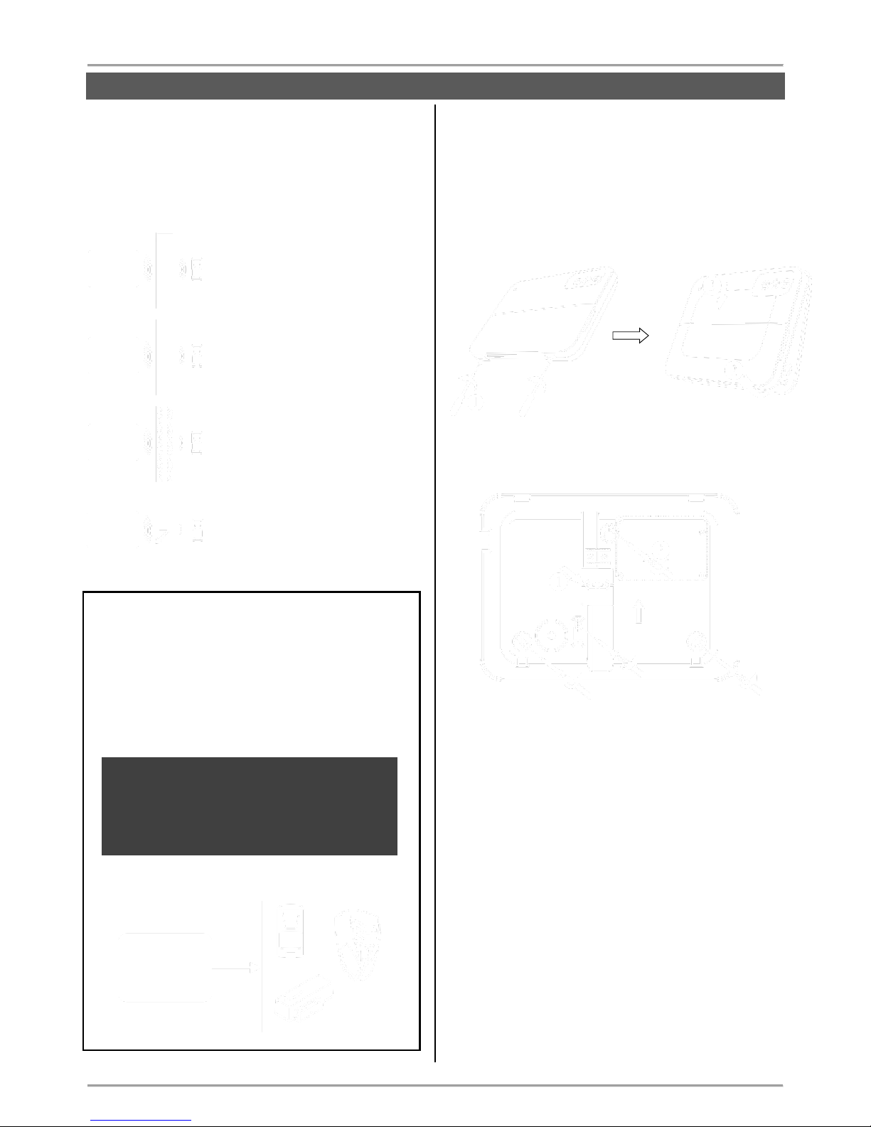
3.1. Preparation for mounting ............................................ 5
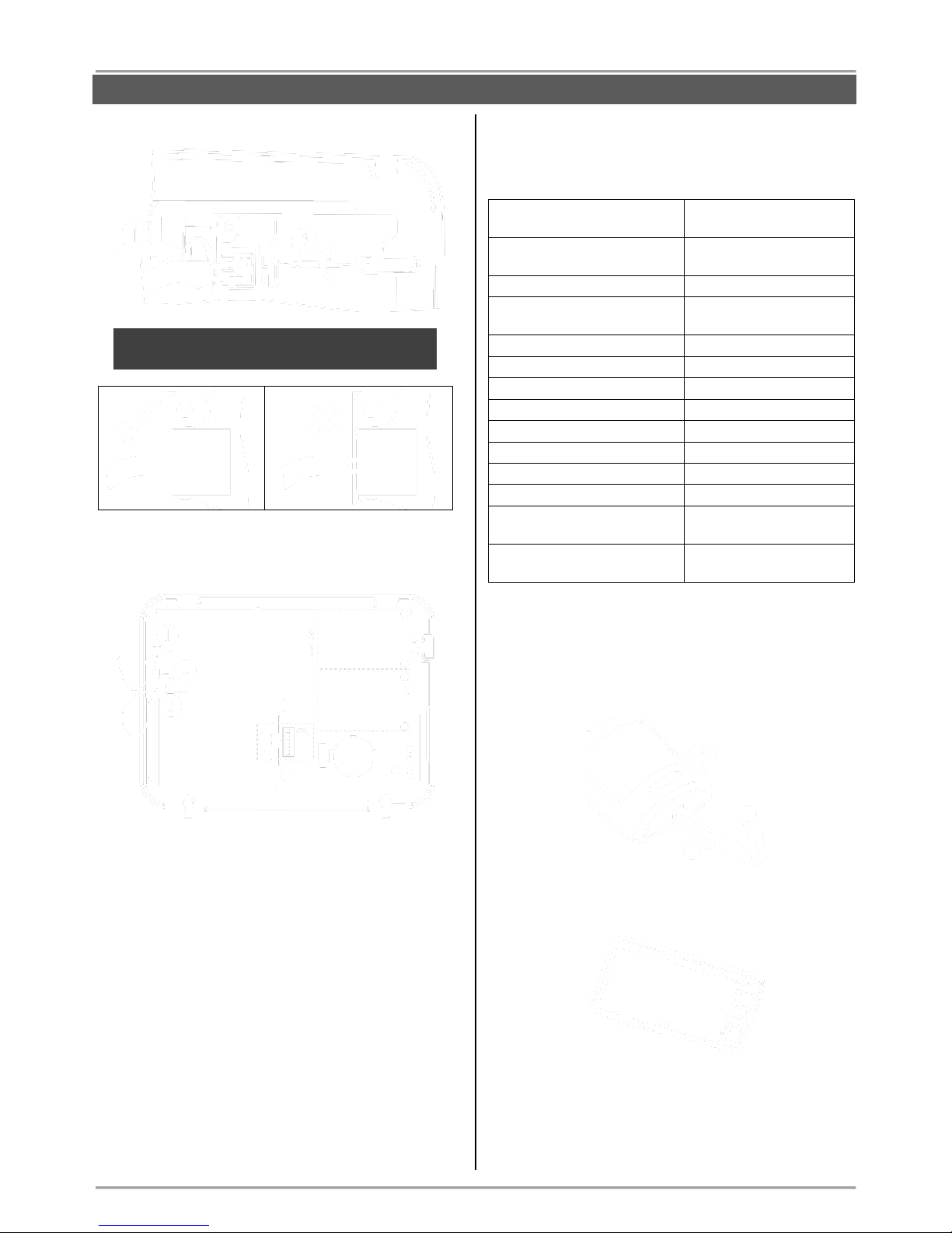
3.2. Mounting and connection of ............................................ 6
BRAVO EXT ...................................................................... 6
3.3. Mounting and connection of........................................ 6
BRAVO INTR ..................................................................... 6
3.4. Mounting of BRAVO PIR ............................................ 7
3.5. Mounting of BRAVO MC ............................................. 9
3.6. Mounting of BRAVO SR 200 .................................... 10
3.7. Mounting of BRAVO SR300 ..................................... 11
3.8. Mounting of BRAVO FL ............................................ 12
3.9. Mounting of BRAVO FD............................................ 13
3.10. Preparing of BRAVO RC ........................................ 14
3.11. Mounting of communication modules ..................... 15
3.11.1. BRAVO GPRS Module ........................................ 16
3.11.2. BRAVO PSTN Module ......................................... 16
3.11.3. BRAVO PSTN VD Module ................................... 17
3.11.4. BRAVO MOUT Module ........................................ 17
4. Hardware Settings ........................................................... 19
4.1. Dip-switches ............................................................. 19
4.2. Type configurations of the zones .............................. 19
4.3. Hardware reset ......................................................... 20
4.4. Sound signalization from the panel ........................... 20
5. Description of the Front Panel .......................................... 21
5.1. Buttons ..................................................................... 21
5.2. LED Indication .......................................................... 22
6. Device Enrolment ............................................................. 23
6.1. Access to the Device Enrolment mode ..................... 23
6.2. General steps for enrolling a detector ....................... 23
6.3. General steps for enrolling a key fob ........................ 23
6.4. General steps for enrolling an outdoor sounder ........ 24
7. Test of Devices ................................................................ 25
7.1. Radio test of devices ................................................ 25
7.2. Key fob operation test ............................................... 25
7.3. Outdoor sounder operation test ................................ 25
7.4. Zone Walk Test ........................................................ 25
7.5. Bypassing of Devices ............................................... 25
7.6. Deleting of Devices ................................................... 26
7.7. Resetting Detectors and Sounders ........................... 26
7.8. Resetting Key Fobs .................................................. 26
7.9. Programming of parameters with ProsTE Software .. 27
7.10. Default Parameters after Hardware Reset
7.11. Firmware Update .................................................... 36
8. Arm and Disarm Management ......................................... 37
8.1. Full Arming Mode ..................................................... 37
8.2. Stay Arming Mode .................................................... 37
8.3. Disarming ................................................................. 37
8.3.1. Disarming via key fob ............................................ 37
8.3.2. Disarming via panel buttons .................................. 37
9. Operation with the System........................................... 38
9.1. Reviewing of Alarm events ....................................... 38
9.2. Clearing of Alarm events .......................................... 38
9.3. Reviewing Troubles Mode ........................................ 38
9.4. Reviewing of Bypassed Devices ............................... 38
9.5. Erasing the Log Memory........................................... 38
9.6. Changing Signal Strength of a Key Fob ................... 38
10. Replacing Batteries ................................................... 39
10.1. Replacing the Panel Battery ................................... 39
10.2. Detectors (PIR, MC, FL, FD) .................................. 39
10.3. Key Fob .................................................................. 39
10.4. Outdoor sounder ..................................................... 39
11. Object Cart ................................................................ 40
- Teletek Electronics JSC is not responsible for any
damages caused on the BRAVO panel when the
user uses other power adapter types with similar
technical characteristics but not approved from the
manufacturer.
- When changing batteries in the BRAVO control
panel or periphery devices, the user must use only
the ones approved by Teletek Electronics JSC and
with the described in this manual technical
specifications and parameters.
- The BRAVO panel is designed according and with
conformity to high standards for test and operation
for wireless alarm control systems. However, it is
possible some limitations to occur in operation,
due to low transmission power and limited
frequency range:
A) The receivers operation could be disturbed or
blocked by radio signals occurring on or close their
operation frequencies, regardless of the digital
algorithm used.
B) Every receiver can respond only to one
transmitted signal at a time.
C) All wireless devices should be tested regularly with
purpose to find any sources of interference and to
protect the whole system against unexpected faults.
- The user must be cautioned that any changes or
modifications of the BRAVO panel and the wireless
periphery, which is not specially approved by
Teletek Electronics JSC, could void the supported
documentation and certification.
Attention:
This manual contains information on limitations
regarding product use and function and
information on the limitations as to liability of the
manufacturer. The entire manual should be
carefully read.
The information in this manual is a subject to
change without notice!
WARNINGS
TABLE OF CONTENTS
!

BRAVO –Wireless Alarm Control Panel
3
1. General Information for the System
BRAVO is a wireless alarm control panel suitable for
installation in residential houses and small offices. The
system is very easy to control via key fobs or
MobileTTE smartphone application*.
*requires GPRS module installed to the panel
Up to two communication modules (GPRS, PSTN,
PSTN VD or MOUT/PGM) can be added to the system
for programming via AjaxWEB web interface or
MobileTTE smartphone application.
Some additional settings are available via specialized
ProsTE programming software. The connection to the
panel is realized with a standard USB - mini USB
cable. The USB interface is located on the left outer
side of the panel’s box and it is accessible without
opening the front cover.
Available for purchase:
The BRAVO panel is available for purchasing as:
1. A control panel, without peripheral devices included;
2. A kit, including a control panel and a set of
peripheral devices, prepared in advance for direct
mounting on the protected site.
Supported types of peripheral devices:
BRAVO PIR – Passive infrared detector
BRAVO MC – Magnetic contact
BRAVO FL – Flood detector
BRAVO FD – Fire detector
BRAVO RC – Key fob remote control
BRAVO SR200 – Outdoor sounder
BRAVO SR300 – Outdoor sounder
GENERAL INFORMATION
Technical and Functional Characteristics
General for the Panel
- Type of the indication
LED
- Areas
1
- Max. zones/ detectors
16 (including PIR, MC, FL, FD)
- Max. key fobs remote controls
8
- Max. outdoor sounders
1; 115dB
- Built-in sounder
85 dB
- Memory LOG file
256 events
Wireless connection
- Frequency
868MHz – 869MHz (Adaptive Frequency Agility Algorithm)
- Type
Two-way communication
- Signal coding
YES; According the requirements of Grade 2
- Detecting of radio interference
YES; According the requirements of Grade 2
Main power supply of the panel
- BRAVO EXT
Adapter AC-DC; 5 VDC/ 1A
- BRAVO INTR
Built-in power supply unit: 100-240 VAC; 50-60Hz
Consumption
- BRAVO EXT
200mA
- BRAVO INTR
150mA
Back-up power supply of the panel
- Battery
1 х 3.7 V/ 4000mAh, Li-Po (Type А according EN50131
Grade 2), max. size 80х65х10mm
Environment
- Operation temperature
0°C up to +40°C, Class II (indoor mounting)
- Degree of protection
IP30
- Relative humidity
93% @ +30°C
- Size
220х160х38mm
- Weight, kg
BRAVO EXT – 1,223kg; BRAVO INTR – 1,376kg
- Material
ABS plastic

BRAVO –Wireless Alarm Control Panel
4
2. Planning Your Wireless System
In order to achieve the best efficiency of your wireless
system, prior to installation plan the location of the
control panel and the wireless devices within the
premises.
The installation place of the control panel should be
in premises located above the ground level.
Minimize the number of obstacles between the
control panel and the wireless devices to obtain a
stronger signal.
The control panel should be installed in a minimum
distance of at least 2 meters far from other sources
of radio signals (Wi-Fi or Bluetooth routers, wireless
telephone stations, etc.).
ATTENTION: Do not install the panel close to
sources of strong radio fields as these can cause
interference and thus diminish the serviceability
of the system and its radio band.
The control panel should be installed approximately
within the center of the protected premises.
The minimum distance between the panel and
enrolled peripheral devices must be 1 meter to
guarantee the proper operation of the system,
including in test mode.
In case of installing the control panel in a corner,
leave the following minimum distances:
o 20 cm on the left side surface to provide a free
access to the USB interface input for
programming with ProsTE software;
o 5 сm on all other sides of the box for providing a
proper ventilation.
ATTENTION: The control panel installation
location should be dry and should not be
subjected to harsh temperature changes.
The control panel should be installed close to
grounding and telephone cables.
> 20 cm.
GENERAL INFORMATION
> 2 m
Power lines
Wi-Fi/ Bluetooth routers
Wireless telephone
stations
> 5 cm.
> 5 cm.
0°С
40°С
Entrance
> 1 m

BRAVO –Wireless Alarm Control Panel
5
The construction and the width of the walls between
the premises also affect the radio signals
transmitted between the devices and the control
panel.
Attention: In the table below are listed approximate
values.
The quality of the radio coverage
and signal strength is reduced with
10-20% in premises with
plasterboard and wood walls.
The quality of the radio coverage
and signal strength is reduced with
30-40% in premises with brick
walls.
The quality of the radio coverage
and signal strength is reduced with
40-60% in premises with concrete
and building blocks walls.
The quality of the radio coverage
and signal strength is reduced with
80%, and sometimes with 100%
(full reflection) in premises with
metal walls or surfaces.
ATTENTION:
If you need to increase the panel’s sensitivity for
receiving the signals from the wireless devices
(because of specific conditions in the premises like
reinforced walls between the rooms, security zones
in a great distance from the panel, etc.), you can
make additional settings in the panel – move the dip
switch 8 in ON position – see section “Hardware
setting” (item 4).
In increased sensitivity for receiving signals
operation mode, the minimum distance
between the panel and enrolled peripheral
devices must be 2 meters to guarantee the
proper operation of the system, including in test
mode.
3. Basic Steps for Installation
3.1. Preparation for mounting
Undo the two screws fixing the cover to the bottom
and open the panel’s enclosure.
Attention: The screws are with interrupted thread
and you do not need to undo them all. They must
stay fixed to the cover.
Mount the bottom of the box as use appropriate
fixing elements according the mounting surface.
1. Break out the plastic cap from the bottom to
fix the main power cable – see the steps for
mounting of BRAVO INTR (item 3.3).
2. Fix the bottom to the mounting surface and
level it horizontally before the final fixing with
the supporting screws.
GENERAL INFORMATION
> 2 m

BRAVO –Wireless Alarm Control Panel
6
3.2. Mounting and connection of
BRAVO EXT
Run the connector of the power adapter through the
main cable channel and lead it on the internal side of
the bottom.
The cable length of the power adapter is ~1700mm,
so you have to locate the panel installation place
near a power socket.
ATTENTION: Use only the original power supply
adapter 5V/ 1A, supplied with control panel!
Prepare the panel for connecting to the mains power
230V.
1. Connect the power adaptor connector to the
input on the panel’s PCB.
2. The cable of the battery must be connected
to the “Battery” terminal.
3. Set the dip-switches position according the
system configuration – see the section
“Hardware settings” (item 4).
4. Switch on the battery – set the mini switch in
“ON” position.
Close the panel’s box following the steps in item 3.1
in a reverse order.
Plug in the power adapter in the socket and proceed
with peripheral device enrolment – see the section
“System Configuration” (item 6).
3.3. Mounting and connection of
BRAVO INTR
BRAVO INTR is a wireless alarm panel with built-in
power supply unit, which is factory mounted to the
bottom of the box.
Prepare the panel for connecting to the mains power
230V.
1. Run the mains power supply cable through
the main cable channel and lead it on the
internal side of the bottom.
2. Fix the mains power cable to the bottom
using the plastic cap and screws from the spare
parts kit.
3. Connect the mains power cable to the “L N”
terminal as observe the polarity.
4. Assure that a special cable is connected to
“5VDC” terminal.
Note: Position the cable for 5 VDC power
supply as shown on the picture and observe
keeping this position when you close the
BRAVO INTR box!
ATTENTION: Switch on the mains power supply
(230V +10%/-15%, 50-60Hz) ONLY AFTER the
final closing of the panel’s box and switched on
battery!
The installer should strictly observe the polarity of
the electrical connection when connecting the power
cable to “L N” terminal. The ends of the power cable
should be clearly stripped and fixed tightly to the
terminal of the power supply unit – use a plain
screwdriver to tight the screws.
INSTALLATION
Places for
mounting of
communication
modules
Slot 1
Slot 2

BRAVO –Wireless Alarm Control Panel
7
ATTENTION: The wires should be placed tight in
the socket terminals!
Connect the cable on “5VDC” terminal to the same
terminal on the panel’s PCB.
1. Connect the cable on “5VDC” terminal of the
power supply unit to the “5VDC” terminal on the
panel’s PCB.
2. The cable of the battery must be connected
to the “Battery” terminal.
3. Set the dip-switches position according the
system configuration – see the section
“Hardware settings” (item 4).
4. Switch on the battery – set the mini switch in
“ON” position.
Close the panel’s box following the steps in item 3.1
in a reverse order.
Switch on the mains power supply and proceed with
peripheral device enrolment – see the section
“System Configuration” (item 6).
3.4. Mounting of BRAVO PIR
BRAVO PIR is a wireless passive infrared detector for
detecting of movement.
Technical Characteristics:
Battery
1 х 3 V/ 1500mAh,
CR123A type
Battery life
(max. without LED)
3 years
Operation frequency
~868 MHz
Radio distance
(open space)
Up to 400m
Working temperature
-10°C - +50°C
Storing temperature
- 40°C - +50°C
White light immunity
5 200 Lux
Walk detection speed
0.3 m/s - 3.0 m/s
Coverage angle
90°
Mounting height
1.5 - 3.6 m (2.1 m)
Number of detection zones
54
Dimensions
66 x 132 x 60 mm
Range when mounted in a
corner
12 m x 12 m (90°)
Range when mounted on a
wall
17 m x 15 m (110°)
Mounting
1. Open the detector box as use small plain screwdriver
– use a small flat screwdriver and slightly press at the
opening in the bottom side and then open the cover up.
2. Remove the detector PCB by pressing the clip
downward and pull it out.
3. Mount the detector at the place of installation. Use
the respective opening according the mounting location
– on a wall or in a corner.
Places for
mounting of
communication
modules
Slot 1
Slot 2
INSTALLATION

BRAVO –Wireless Alarm Control Panel
8
ATTENTION: When the detector is installed
on a mounting bracket, it is impossible to use
the second tamper-switch for self-protection
(on the back side of the PCB) and the
requirements of standard EN50131 Grade 2
are not covered!
Use the elements for the second tamper-switch,
according the place of installation:
4. Mount the PCB back onto the base by placing it first
on the front clips.
5. Enroll the detector to the panel configuration as follow
the steps described at item 6.2 in “System
Configuration” section.
Description of the PCB elements
1 – Protection folio for the battery; it is removed directly
before the enrolment of the detector to the panel.
2 – ENROLL Button. Use it to enroll the detector to the
panel.
3 – The first tamper-button for self-protection. Used for
signaling in case of removing the detector’s cover.
4 – RST (RESET) Button. Use it to reset the detector.
5 – DOUBLE KNOCK Jumper (“Double knock”
operation mode). Set a jumper on the terminals (on the
right side) to activate the “Double knock” operation
mode.
6 - BACK TAMPER Jumper (follows the state of the
second tamper-switch for self-protection). Set a jumper
on the terminals (at the left side) to enable the operation
of the second tamper-switch.
7 – Motion sensor.
8 - Antenna.
9 – The second tamper-button for self-protection. Used
for signaling in case of removing the detector’s box from
the mounting surface – it is enabled when there is a
jumper set at BACK TAMPER terminals.
Mounting on a wall
Mounting in a corner
Place for
mounting
bracket
Mounting
on a wall
Break the
pin
Mounting
in a
corner
Break the
pin

BRAVO –Wireless Alarm Control Panel
9
3.5. Mounting of BRAVO MC
BRAVO MC is a wireless magnetic contact detection of
door or window opening. BRAVO MC has a wired zone
input for connecting of wired magnetic contact.
Technical Characteristics:
Battery
1 х 3 V/ 1500mAh,
CR123A type
Battery life
(max. without LED)
3 years
Operation frequency
~868 MHz
Radio distance
(open space)
Up to 400m
Working temperature
-10°C - +50°C
Storing temperature
- 40°C - +50°C
Operation distance
25-30mm
Wired zone input
1
Dimensions
93 x 31 x 27 mm
Mounting
1. Remove the bases of BRAVO MC and the magnet.
2. Mount the bases on the place of installation, as pay
attention to the position of the magnet in relation to the
BRAVO MC body – see the picture below.
Note: To use the wired zone input you have to
drill an additional hole for the cables.
ATTENTION: Remove the plastic cover from the
base to ensure the double action of tamper
button for self-protection.
3. Enroll the detector to the panel configuration as follow
the steps described at item 6.2 in “System
Configuration” section.
4. Mount back the magnet and BRAVO MC to their
bases.
ATTENTION: Use the plastic pads when
installing the magnet on metal surfaces. The
pads will protect the magnet field from a “short-
circuit”.
Description of the PCB elements
1 – Protection folio for the battery; it is removed directly
before the enrolment of the detector to the panel.
2 – Tamper button for self-protection.
3 – ENROLL Button. Use it to enroll the detector to the
panel.
4 – RST (RESET) Button. Use it to reset the detector.
5 – Terminal for connection of wired zone.
6 – “Pulse” Jumper.
7 - Antenna.
INSTALLATION
Plastic
cover

BRAVO –Wireless Alarm Control Panel
10
3.6. Mounting of BRAVO SR 200
BRAVO SR 200 is a wireless electrodynamic siren for
outdoor mounting.
Technical Characteristics:
Battery
3 х 3 V/ 15Ah,
CR4615 type, size D
Battery life (max. without LED)
3 years*
Operation frequency
~868 MHz
Radio distance (open space)
Up to 400m
Working temperature
-30°C - +65°C
Storing temperature
- 40°C - +65°C
Sounder volume
115dB/ 1 m
Dimensions
180 x 210 x 85 mm
* Based on normal use of the siren (e.g. 1 alarm per month with strobe
and 1 minute alarm cycle, and 8 squawks per day at an average of
25°C). If the use is more frequent or the alarm cycle is set for more
than 1 minute the battery life may be reduced.
Using optional power supply with adapter 12V/1A will extend the
battery life.
Mounting
1. Use a small flat screwdriver to lift up and remove the
orange plastic cap. Undo the screw fixing the plastic
cover to the base. Lift up the siren cover and remove it.
2. Remove the light pipe, undo the screws and remove
one by one the metal and the plastic covers protecting
the battery and the electronic parts.
3. Use the drilling template on the back side of the
packing box to mark and drill the holes for installation.
4. Mount the siren base as first fix the screw for the
main installation hole, then lever the siren, and at the
end fix the supporting screws on the both sides.
5. Set the tamper position as use the screw on it –
regulate the position so that the screw end to contact
with the installation surface, and the contact plate to be
pressed when the cover of the siren is closed (the plate
must be horizontal and when pressed with siren cover
to close the tamper button under it – a click is heard).
6. Enroll the siren to the panel configuration as follow
the steps described at item 6.4 in “System
Configuration” section.
Description of the PCB elements
1 – Terminal for connecting the battery.
2 – LED for siren status.
3 – LED signalization in Alarm mode.
4 - Terminals SPK (SPEAKER) and TAMPER for
connecting the sounder and tamper button wires.
5 – ENROLL Button. Use it to enroll the siren to the
panel.
6 – RST (RESET) Button. Use it to reset the detector.
7 – Terminals +12VDC and GND for optional power
supply with adapter 12VDC/ 1A – see also item 10.4.
8 - Antenna.
INSTALLATION

BRAVO –Wireless Alarm Control Panel
11
3.7. Mounting of BRAVO SR300
BRAVO SR300 is a wireless piezo siren for outdoor
mounting. The siren is available in two variant according
the type of the used batteries: BRAVO SR300 AKL and
BRAVО SR300 LIT.
Technical Specifications:
Battery:
- BRAVO SR300 ALK
- BRAVO SR300 LIT
4х1.5V, alkaline, LR14
2х3V, Li-MnO2
Battery life (max. without
LED)
3 years*
Battery low voltage signal
sent:
- BRAVO SR300 ALK
- BRAVO SR300 LIT
At value <5.1VDC
At value <5.5VDC
Operation frequency
~868 MHz
Radio distance (open space)
Up to 400m
Working temperature:
- BRAVO SR300 ALK
- BRAVO SR300 LIT
-10°C - +40°C
-25°C - +60°C
Sounder volume
110dB/ 1 m
Dimensions
310 x 230 x 60 mm
* Based on normal use of the siren (e.g. 1 alarm per month with strobe
and 1 minute alarm cycle, and 8 squawks per day at an average of
25°C). If the use is more frequent or the alarm cycle is set for more
than 1 minute the battery life may be reduced.
Using optional power supply with adapter 12V/1A will extend the
battery life.
Mounting
1. Lift up the cover and remove it from the base. Undo
the screws and remove one-by-one the metal and the
plastic covers.
2. Use the drilling template on the back side of the
packing box to mark and drill the holes for installation.
3. Mount the siren base as first fix the screw for the
main installation hole, then lever the siren, and at the
end fix the supporting screws on the both sides.
4. Set the tamper position as use the screw on it -
regulate the position so that the screw end to contact
with the installation surface, and the contact plate to be
pressed when the cover of the siren is closed (the plate
must be horizontal and when pressed with siren cover
to close the tamper button under it - a click is heard).
5. Enroll the siren to the panel configuration as follow
the steps described at item 6.4 in “System
Configuration” section.
Description of the PCB elements
1 – Terminal for connecting the battery.
2 - LED for siren status.
3 – LED signalization in Alarm mode; Optional LED
signalization in standby mode (“chasing LEDs” type).
4 - Terminals SPK (SPEAKER) and TAMPER for
connecting the sounder and tamper button wires.
5 – ENROLL button. Use it to enroll the siren to the
panel.
6 – RESET Button. Use it to reset the detector.
7 – Terminals +12VDC and GND for optional power
supply with adapter 12VDC/ 1A – see also item 10.4.
8 – LED Terminals. Set a jumper to switch on the
optional “chasing LEDs” signalization.
Attention: Using the optional “chasing LEDs”
signalization in standby mode will reduce the battery
life.
INSTALLATION

BRAVO –Wireless Alarm Control Panel
12
3.8. Mounting of BRAVO FL
BRAVO FL is a wireless flood detector.
Technical Characteristics:
Battery
1 х 3 V/ 1500mAh,
CR123A type
Battery life
(max. without LED)
3 years
Operation frequency
~868 MHz
Radio distance
(open space)
Up to 400m
Working temperature
-10°C - +50°C
Storing temperature
- 40°C - +50°C
Dimensions:
- body
- flood sensor
93 x 31 x 27 mm
64 х 19 х 13 mm
Connection wires
2х0,35mm, white,
2 meters
Mounting
1. BRAVO FL is prepared for direct mounting at the
place of the installation. The main body and the flood
sensor are connected with wires 2 meters long.
2. Remove the base of BRAVO FL and prepare it for
mounting at the place of installation.
Note: The base of the detector can be mounted also
with double-sided mounting tape at the place of
installation.
3. Mount the flood sensor at max. 5 mm distance from
the floor of the protected room, and the main body
above is at higher position – up to 2 meters.
ATTENTION: Do not cut and change the length
of the connecting wires!
4. Enroll the detector to the panel configuration as follow
the steps described at item 6.2 in “System
Configuration” section.
Note: You can enroll BRAVO FL to every
position (zone number) from 3 to 16, as the “24-
hour security zone” zone type is set
automatically.
Description of the PCB elements
1 – Protection folio for the battery; it is removed directly
before the enrolment of the detector to the panel.
2 – ENROLL Button. Use it to enroll the detector to the
panel.
3 – RST (RESET) Button. Use it to reset the detector.
4 – Terminals for wired water (flood) zone – 2 meters
long wires are factory connected.
5 - Antenna.
INSTALLATION
Main body
Flood sensor
2 m
Max.
5 mm
Connecting
wires

BRAVO –Wireless Alarm Control Panel
13
3.9. Mounting of BRAVO FD
BRAVO FD is wireless combined fire alarm detector
with optical-smoke and heat (rate-of-rise) parts.
Technical Characteristics:
Battery
2 х 3 V/ 1500mAh,
CR123A type
Battery life
(max. without LED)
3 years
Operation frequency
~868 MHz
Radio distance
(open space)
Up to 400m
Working temperature
-10°C - +50°C
Storing temperature
- 40°C - +50°C
Mounting height
Up to 16m
Protected area
Up to 120m2
Dimensions
(including base)
103х56mm
Sensitivity
Rate-of-rise 10ºC/ min
(max 60ºC)
Class for the heat part,
according EN54-5
A1R
Mounting
1. Remove the detector from the base as rotate both
parts opposite to each other – the base clockwise and
the detector counter clockwise.
2. Mount the base at the place of installation.
ATTENTION: Avoid placing the detector close to
the following sources of interference:
- heated surfaces;
- direct air flows from chimneys, windows, fans
and sources of evaporation
- smoke, ash and other contaminators.
3. Enroll the detector to the panel configuration as follow
the steps described at item 6.2 in “System
Configuration” section.
Note: You can enroll BRAVO FD to every
position (zone number) from 3 to 16, as the “24-
fire zone” zone type is set automatically.
4. Mount the detector back to the base – locate the
marker on the outer side of the detector’s body to
coincide with the short pin on the outer side of the base.
Then rotate the detector clockwise until the marker
coincides with long pin on the outer side of the base.
Description of the PCB elements
1 – Protection folio for the batteries; it is removed
directly before the enrolment of the detector to the
panel.
2 – ENROLL Button. Use it to enroll the detector to the
panel.
3 – RST (RESET) Button. Use it to reset the detector.
4 – LED for the current status of the detector
5 – Tamper button for self-protection.
INSTALLATION
Mounting
holes

BRAVO –Wireless Alarm Control Panel
14
3.10. Preparing of BRAVO RC
BRAVO RC is a key fob remote control for:
- Arming and Disarming of BRAVO system;
- Information for the system status;
- Information for current alarm events via LED and
sound signalization.
Technical Characteristics:
Battery
1 х 3 V/ 600 mAh,
CR2450 type
Battery life
(max. without LED)
3 years
Operation frequency
~868 Mhz
Radio distance
(open space)
Up to 200m
Working temperature
-10°C - +50°C
Storing temperature
- 40°C - +50°C
Dimensions
32х65х16mm
Switching on the battery
1. Remove the back cover of the key fob as undo the
two screws:
2. Remove the protecting folio:
3.Close the cover of the remote control.
4. Enroll the key fob to the panel configuration as follow
the steps described at item 6.3 in “System
Configuration” section.
Note: You can find detailed information for operation
with the key fobs by User in items 8 and 9 of this
manual.
The sequence for replacing the battery of a key fob is
described in item 10.3.
Specialized LED indication of a key fob
The button has different LED and sound signalization
when a control button is pressed:
Button
Color
Sound
Action
Green
Two signals
Full Arming
Green
One signal
According the
programmed for
the button*
Green
Three signals
Disarming
All
Yellow
Long signal
Battery low of the
remote control**
Red
Long signal
No communication
with the panel
* The functionality of the button is programmed with ProsTE software
as the action can be different for every one remote key-fob.
** The indication is visualized after the indication of the main action of
the pressed button and refers to the used key-fob.
By pressing the button of the key fob the user is
informed for the current system status and alarm
events:
LED
Color
Sound
Description
Green
Three signals
System is disarmed
Red
Two signals
System is armed
Red
blinking
Combined
melody
Alarm memory
(in disarming)
INSTALLATION

BRAVO –Wireless Alarm Control Panel
15
3.11. Mounting of communication modules
Different in functionality communication modules are
designed for operation with BRAVO wireless panel.
The BRAVO panel can operate with up to two
communication modules at the same time, mounted to
Slot 1 and Slot 2 on the main PCB of the panel.
ATTENTION: The communication modules must
be added to the system configuration ONLY
WHEN both main power supply from the control
panel and back-up battery are SWITCHED OFF.
ATTENTION: The communication modules must
be enabled for operation via ProsTE software or
AjaxWEB web application.
The priority in operation (sensing of messages for
events) is set via mini dip-switch 6 on the panel’s PCB –
see also item “4. Hardware settings”.
When the “Alternative” communication type is set
(position OFF of mini dip-switch 6), the priority for
message distribution is as follows:
Slot 1 – Main communication channel.
Slot 2 – Backup communication channel.
You can find more detail description of the settings and
parameters for supported communication modules in
item 7.9 – Programming of parameters with ProsTE
software, menu “6. Slots”.
Types of communication modules from BRAVO series:
Module
Functionality
Monitoring
and control
GPRS
- Sending of messages for
events to Users;
- Remote management –
Arming and Disarming;
- Remote management of
zones (bypass/ de-bypass);
- Reviewing the memory log
events;
- Programming of panel
parameters (Ajax WEB).
MobileTTE
Ajax WEB
PSTN
- Sending of messages for
events to 4 phone numbers;
- Choosing of communication
protocol SIA, CID or User.
-
PSTN
VD
- Sending of messages for
events to 4 phone numbers
with voice messaging;
- Remote control of system
(arm/disarm) over PSTN with
voice guiding.
PSTN
(“Voice
Dialer”
protocol set)
MOUT /
PGM
- MOUT Mode. Sending of
messages for events via
transmitter to a monitoring
station; connecting f outdoor
siren with external power
supply.
- PGM Mode. Remote control
of home automation devices
using the PGM outputs of the
module.
MobileTTE
Ajax WEB
Interface connectors
for mounting of
communication
modules
Slot 1
Slot 2
INSTALLATION

BRAVO –Wireless Alarm Control Panel
16
3.11.1. BRAVO GPRS Module
Mounting
1. Remove the cover of the panel – see item 3.1. Switch
off the main and backup power supply.
Mount BRAVO GPRS module to Slot 1 or Slot 2 on the
main PCB.
2. Fix the module with screws to the panel’s PCB.
3. Place a SIM card as shown on the picture.
ATTENTION: The PIN check option of the SIM
card must be disabled!
4. Switch on the main and backup power supply and
close the cover of the box.
5. Use the ProsTE software (see the connection
between the panel and PC in item 7.9) to enable the
module for operation and to set additional parameters if
needed.
Description of the PCB elements
1 – An interface connector for coupling with the panel’s
PCB (on the back side of the module PCB).
2 – LED indication for the module status:
Color
Description
Red
(light on)
Problem with the SIM card; problem with the
GPRS channel; no communication between
the module and the server.
Orange
(blinking)
The module is sending messages via back-up
channel.
Green
(blinking)
The module is in normal operation mode (the
connection with the server is stable and the
transmitting of messages is successful).
3 – LEDs for radio signal strength:
- All OFF: No signal.
- 1 LED lighting: Low signal.
- 2 LEDs lighting: Good signal.
- 3 LEDs lighting: Very good signal.
4 – Antenna.
5 – Mounting holes.
6 – Holder for the SIM card.
3.11.2. BRAVO PSTN Module
Mounting
1. Remove the cover of the panel – see item 3.1. Switch
off the main and backup power supply.
Mount BRAVO PSTN module to Slot 1 or Slot 2 on the
panel’s PCB.
2. Fix the module with screws to the panel’s PCB.
3. Connect the telephone line to the terminals Т and R,
and the telephone device to terminals T1 and R1. There
are no requirements for the polarity of the connection.
4. Switch on the main and backup power supply and
close the cover of the box.
5. Use the ProsTE software (see the connection
between the panel and PC in item 7.9) to enable the
module for operation and to set additional parameters if
needed.
6. Perform communicator test as described in item 9.7.
Description of the PCB elements
1 – An interface connector for coupling with the panel’s
PCB (on the back side of the module PCB).
2 – Mounting holes.
3 – Terminals for connecting of telephone line and
device.
4 - LED indication for the module status:
Color
Description
Red
The telephone line is missing. The module
is unable to send message for an event.
Green
The module is in normal operation mode
(the connection with the telephone line is
stable and the transmitting of messages is
successful).
INSTALLATION

BRAVO –Wireless Alarm Control Panel
17
3.11.3. BRAVO PSTN VD Module
Mounting
1. Remove the cover of the panel – see item 3.1. Switch
off the main and backup power supply.
Mount BRAVO PSTN VD module to Slot 1 or Slot 2 on
the panel’s PCB.
2. Fix the module with screws to the panel’s PCB.
3. Connect the telephone line to the terminals Т and R,
and the telephone device to terminals T1 and R1. There
are no requirements for the polarity of the connection.
4. Switch on the main and backup power supply and
close the cover of the box.
5. Use the ProsTE software (see the connection
between the panel and PC in item 7.9) to enable the
module for operation and to set additional parameters if
needed.
6. Perform communicator test as described in item 9.7.
Description of the PCB elements
1 – An interface connector for coupling with the panel’s
PCB (on the back side of the module PCB).
2 – Mounting holes.
3 – Terminals for connecting of telephone line and
device.
4 - LED indication for the module status:
Color
Description
Red
The telephone line is missing. The module
is unable to send message for an event.
Green
The module is in normal operation mode
(the connection with the telephone line is
stable and the transmitting of messages is
successful).
5 – Holder with a mini SD card. The voice messages for
events are recorded to the mini SD card.
3.11.4. BRAVO MOUT Module
Mounting
1. Remove the cover of the panel – see item 3.1. Switch
off the main and backup power supply.
Mount BRAVO MOUT module to Slot 1 or Slot 2 on the
panel’s PCB.
2. Fix the module with screws to the panel’s PCB.
3. Connect the outputs of the module according the
application of the module.
ATTENTION: The functionality of the outputs can be set
in one of two operation modes using ProsTE software:
- MOUT – Transmitting signals to radio transmitter or
connecting of wired siren (see Examples 1 and 2).
- PGM – Programmable outputs OC, 100mA.
4. Switch on the main and backup power supply and
close the cover of the box.
Description of the PCB elements
1 – An interface connector for coupling with the panel’s
PCB (on the back side of the module PCB).
2 – Mounting holes.
3 – Terminal row:
Output
MOUT Mode
PGM Mode
On / P1
Event “Arm / Disarm”.
OC, 100mA
A / P2
Event “Burglary Alarm”.
OC, 100mA
T / P3
Event “Tamper / Lost
device”.
OC, 100mA
P / P4
Event “Panic Alarm”.
OC, 100mA
F / P5
Event “Fire Alarm”.
OC, 100mA
S / P6
Event “Siren” – repeats
the alarm cycle of a
connected wired siren
(the silent alarms do not
affect at this output).
OC, 100mA
SirTmp
Jumper for disabling the
signals from a wired siren
connected to the module.
-
GND
Common ground.
Common ground.
4 - LED indication for the module status:
Color
Description
Yellow
Power-up initialization mode.
Red
No communication with the panel.
Green
The module is in normal operation mode.
5 – Jumper SirTmp (see the connection diagram
between BRAVO MOUT and wired siren in Application
Example 2).
INSTALLATION

BRAVO –Wireless Alarm Control Panel
18
Application Example 1 (MOUT Mode)
Connection between BRAVO MOUT and radio
transmitter TP2000 for sending messages for events to
monitoring station.
Application Example 2 (MOUT Mode)
Connection diagram between BRAVO MOUT and wired
outdoor siren.
INSTALLATION
ATTENTION:
When the BRAVO MOUT is mounted
on Slot 1 and “Alternative”
communication type is set, the panel
will send messages only through the
main channel and never through the
backup channel, regardless of that
whether the transmitted signal is
received from the monitoring station or
not.
When the BRAVO MOUT is mounted
on Slot 2 and “Alternative”
communication type is set, the panel
will send messages first through the
main channel and in case of failure –
through the backup channel.
External power
supply unit
12V DC
Siren PCB
Compatible outdoor sirens
Note:
The jumper SirTmp must be removed in case
of connection of wired siren to BRAVO MOUT
module, for announcing of the following
technical troubles:
- Open tamper of the wired siren;
- Broken line between wired siren and BRAVO
MOUT module.
When the jumper SirTmp is set, the BRAVO
panel will not follow the status of the connected
wired siren.
Indication of BRAVO panel in case of
connection of wired siren to BRAVO MOUT
One wired siren can be connected to BRAVO
MOUT module. In programming mode and selected
“Sounder Group” the connected wired siren is
shown as device in position 16*.
* Note: The indication will be active directly after the
connection of BRAVO MOUT module to the panel’s PCB
and set MOUT operation mode.
For correct operation of the siren it is obligatory to
connect 2x680K resistors as shown on the
connection diagram.
The wired siren can be bypassed like all other
wireless devices in the system.
In case of technical trouble with the wired siren
(tamper signal or broken line between the siren and
BRAVO MOUT module) the indication in Technical
troubles review mode is:
External power
supply unit
12V DC

BRAVO –Wireless Alarm Control Panel
19
4. Hardware Settings
4.1. Dip-switches
Use the dip-switches to set some additional settings
according the configuration and operation of the system.
Every dip-switch has two positions ON and OFF used to
set certain functionality.
Use a small suitable tool to set the position of the dip-
switch.
ATTENTION: The numbers of the dip-switches
are described according their location on the
panel’s PCB.
The dip-switches order and their functionality are
described as:
No
Description
Position
ON
OFF
8
Power RF (Increased
sensitivity of the control panel)
7
Not used
-
-
6
Communication type
All
Altern.
5
Zone types
(see item 4.2)
Config.
2
Config.
1
4
Sound signalization on ARM/
DISARM
(for the built-in sounder only)
3
Clear the bypassed zones on
DISARM
2
LED Indication – panel
(in ARMING)
1
LED Indication - devices
- Enabled; - Disabled
Every change of the position of the dip-switches is
instant and does not require resetting of the panel
for confirmation of the new settings.
All dip-switches are set in OFF position from the
manufacturer after the production.
The setting of the dip-switches does not change
after full hardware reset of the panel.
The current position of the hardware dip-switches
can be checked via the software applications
ProsTE and AjaxWEB.
4.2. Type configurations of the zones
The installer can choose between two basic
configurations for the zone types with setting the
position of dip-switch 5.
The zone type description is as follow:
Entry-Exit – Provides time to arm and disarm the
site. After arming, the detector, which was triggered
off in this zone, will not sound an alarm until the
programmed EXIT TIME expires.
When the entry-exit zone is opened in armed mode
an ENTRY TIME starts running during which the
user must disarm the system. When the entry time
expires and the system is not disarmed the sounders
will alarm for burglary not authorized entry.
Follow – An alarm zone which is active only when
the site is armed. The zone operates
instantaneously. Activating the zone during entry or
exit time does not cause an alarm event.
Instant - An alarm zone which is active only when
the site is armed. The zone operates
instantaneously. Activating the zone during entry or
exit time causes an alarm event.
Fire – 24-hour fire zone. All wireless fire detectors
are automatically attached to this type of zone during
the enrollment. The zone operates instantaneously
when a fire detector is activated as the sounders are
activated and FIRE alarm message is sent via the
available communication channels.
24-hour security zone. All wireless flood detectors
are automatically attached to this type of zone during
the enrollment. The zone operates instantaneously
when a flood detector is activated as FLOOD alarm
message is sent via the available communication
channels.
The description of the zone configurations:
Zone No
Configuration
Type of the
Device
1
2
1
Entry-Exit
Instant
MC or PIR
2*
Entry-Exit
Instant
MC
Follow
PIR
3-16*
Instant, fire
or 24-hour
security
zone
Instant, fire
or 24-hour
security
zone
Every device
* Depends on the type of the enrolled detector to the
zone.
HARDWARE SETTINGS

BRAVO –Wireless Alarm Control Panel
20
4.3. Hardware reset
After hardware reset of the panel all default settings are
restored, the enrolled devices and the memory log
events are deleted.
To perform hardware reset:
1. Switch off the main and the back-up power
supply of the panel.
2. Set a jumper on the RESET terminals.
3. Switch on the main and the back-up power
supply of the panel – the zone LEDs (1-16) are
blinking in sequence in different colors –
signalization “chasing LEDs” type.
4. Remove the jumper from the RESET
terminals – the panel goes to normal operation
mode, as only the status LED is lighting on in
green.
Note: You can skip the chasing LEDs signalization test
as directly remove the jumper from RESET terminals
after switching on the mains and back-up power supply.
After the initial start-up and every resetting, the
panel goes through initialization procedure – the
status LED starts blinking for 10-15 seconds until
the system is established in normal operation
mode.
4.4. Sound signalization from the panel
Signalization
Description
Button*
Single short beep indicating the
pressing of a key.
Confirmation
Two long sound signals, indicating the
system confirmation for executed
operation.
Cancelation
A single long beep, indicating system
incorrectly executed operation.
Entry time*
Continuous beep, indicating intrusion
into an entrance zone.
Exit time*
Short beeps, indicating the system is
armed and the user is required to
leave the entrance zone. Ten seconds
before the exit time is over beep
frequency increases.
Technical
trouble*
Two short beeps at every 20 sec,
indicating a technical trouble. To stop
the signalization - press the
ATTENTION button.
Chime*
Short beeps with subsequently
increasing period, indicating intrusion
into a zone with an activated chime
option when the system is disarmed.
Arming
The dip-switch 4 is set in ON position.
Two short sound signals indicating
system ARMING.
Disarming
The dip-switch 4 is set in ON position.
Three short sound signals indicating
system DISARMING.
* Note: The signalization can be disabled via specialized
ProsTE programming software – see item 7.9.
HARDWARE SETTINGS
Other manuals for BRAVO
1
Table of contents
Other Teletek electronics Security System manuals

Teletek electronics
Teletek electronics SensoIRIS MCP150MR User manual

Teletek electronics
Teletek electronics SR 120 User manual

Teletek electronics
Teletek electronics CA824 User manual

Teletek electronics
Teletek electronics AVA User manual

Teletek electronics
Teletek electronics SensoMAG S30 User manual

Teletek electronics
Teletek electronics CM 120 R Assembly instructions

Teletek electronics
Teletek electronics CA824 User manual

Teletek electronics
Teletek electronics CA62 Assembly instructions

Teletek electronics
Teletek electronics AVA Assembly instructions

Teletek electronics
Teletek electronics SensoMAG R20 User manual