Viking C-1000B Instructions for use

The C-1000B allows single line phones or
phone systems to share a phone line with one
or two Viking doorboxes or paging amplifiers.
The C-1000B provides two Touch Tone con-
trolled relays to operate door strikes or gate
openers and provides doorbox triggered
CCTV camera switching.
Viking doorboxes and paging amplifiers can be
used on single line, residential or home office
applications as well as on fully loaded systems,
because they are no longer limited to installa-
tion on unused trunk ports.
Add One or Two Doorboxes to an Existing
Phone Line and Provide CCTV Camera Control
P
Ph
ho
on
ne
e.
..
..
.7
71
15
5.
.3
38
86
6.
.8
88
86
61
1
h
ht
tt
tp
p:
:/
//
/w
ww
ww
w.
.v
vi
ik
ki
in
ng
ge
el
le
ec
ct
tr
ro
on
ni
ic
cs
s.
.c
co
om
m
• Allows two Viking doorboxes or Viking paging ampli-
fiers to share a single telephone line with a residential
or business telephone system
• Doorbox triggered CCTV camera switching
• Custom ringing mode allows you to distinguish doorbox
calls from C.O. calls
• Compatible with up to two of the following Viking door-
box models: W-1000, W-2000A, or W-3000.
Alternatively, the Analog PABX/KSU station mode
allows compatibility with a single Viking handsfree
phone (E-10, E-20A, E-30, K-1700-3 or 1600A Series)
• Compatible with Viking’s Single Line Paging Controller,
Model SLP-1.
• Call waiting tones indicate which doorbox is calling and
distinguish a doorbox call from a C.O. line call
• Calls can be placed on hold when visitors call from the
doorbox or when paging
• Provides two Touch Tone controlled N.O. or N.C. dry
contact closures (5 amp rating) for door strikes or gate
openers
• Keyless entry/postal lock input
• Built-in talk battery for “No C.O. Line” applications
• Auxiliary contact output for doorbells, lights, etc.
Power: 120V AC/13.8V AC 1.25A, UL listed adapter provided
Dimensions: 133mm x 104mm x 44mm (5.25" x 4.1" x 1.75")
Shipping Weight: 0.9 kg (2 lb)
Environmental: 0° C to 32° C (32° F to 90° F) with 5% to 95%
non-condensing humidity
Door Strike Relay Contacts: 5A @ 30V DC/250V AC maximum
CCTV/Auxiliary Relay Contacts: .5A@ 125VAC, 1A@ 30V DC
Pulse Dialing Detection: 10 pps
Talk Battery: 28V DC
Maximum Doorbox Power Supply Length: 100 ft, 24 awg wire
Connections: (1) 7 position terminal block and (1) 19 position
terminal block
P
Pr
ra
ac
ct
ti
ic
ce
e
T
TE
EL
LE
EC
CO
OM
MS
SO
OL
LU
UT
TI
IO
ON
NS
SF
FO
OR
RT
TH
HE
E2
21
1S
ST
TC
CE
EN
NT
TU
UR
RY
Y
TECHNICAL
TECHNICAL
F
Fe
ea
at
tu
ur
re
es
s
S
Sp
pe
ec
ci
if
fi
ic
ca
at
ti
io
on
ns
s
• Add one or two Viking Doorboxes to your home or
office phones
• Switch between two CCTV cameras automatically
when either doorbox is activated
• Add a Viking SLP-1 Single Line Paging Controller to
provide paging, intercom, loud ringing, door chime
and music on hold features
• Provide commercial or residential security via two-way
handsfree communication from a door or gate
• Use as a line concentrator (one fax machine or
answering machine can answer three lines)
A
Ap
pp
pl
li
ic
ca
at
ti
io
on
ns
s
C-1000B
C-1000B
Door Entry and CCTV
Camera Controller
April 17, 2006
i
in
nf
fo
o@
@v
vi
ik
ki
in
ng
ge
el
le
ec
ct
tr
ro
on
ni
ic
cs
s.
.c
co
om
m

F
Fe
ea
at
tu
ur
re
es
sO
Ov
ve
er
rv
vi
ie
ew
w
DOOR ENTRY / CCTV VIDEO
CONTROLLER
VIKING©MODEL C-1000B
PWR 13.8 VAC
DOOR
STRIKE 1
DOOR
STRIKE 2
DOORBOX 2
DOORBOX
PWR OUTPUT
DOORBOX 1
123456789
10 11 12 13 14 15 16 17 18 19
EARTH
GND
PHONE LINE
INPUT
LINE OUT
TO PHONES
KEYLESS CONTACT
CLOSURE INPUT
VIKING
ELECTRONICS
HUDSON, WI 54016
EARTH
GND
C.O. LINE
INPUT
OUT TO
PHONES
KEYLESS
C.C. INPUT
DOOR
BOX 1
DOORBOX
13VAC PWR
DOOR
BOX 2
N.O. COM N.C.
DOOR STRIKE 1
SIG GND
VIDEO 1 IN
SIG GND
VIDEO 2 IN
SIG GND
VIDEO OUT
N.O. COM N.C.
DOOR STRIKE 2
TALK BATTERY
OFF ON
PWR
ON
1 2 3
COM N.O. N.C. - - - - AUX.
CONTACT
OUTPUT
* Earth Ground
C.O./Phone Line Input
Out to Telephones
Keyless Entry/Postal Lock
Contact Closure Input
Door Box 1 Line Input
Door Strike 1
Contact Output
Door Box 2 Line Input
Doorbox 13V AC Power Output
Door Strike 2
Contact Output
N.C.
COM
N.O.
N.C.
COM
N.O.
D.S.1 D.S.2
CCTV Video 1 Input
CCTV Video 2 Input
CCTV Video Output
Signal
Ground
Signal
Ground
Signal
Ground
N.C.
N.O.
COM
Auxiliary
Contact Output
Power LED - Lights
while unit is powered.
Door Strike 1 LED - Lights
while the door strike 1 relay
is activated.
Door Strike 2 LED - Lights
while the door strike 2 relay
is activated.
Power Input (13.8VAC @ 1.25A
adapter included)
IF YOU HAVE A PROBLEM WITH A VIKING PRODUCT, PLEASE CONTACT: VIKING TECHNICAL SUPPORT AT (715) 386-8666
Our Technical Support Department is available for assistance Monday 8am-4pm and Tuesday-Friday 8am - 5pm central time. So that we can give you better service, before you call please:
1. Know the model number, the serial number and what software version you have (see serial label).
2. Have your Technical Practice in front of you.
3. It is best if you are on site.
WARRANTY
Viking warrants its products to be free from defects in the workmanship or materials, under normal use and service, for a period of one year from the date of purchase from any authorized Viking distributor or 18 months from the date manu-
factured, which ever is greater. If at any time during the warranty period, the product is deemed defective or malfunctions, return the product to Viking Electronics, Inc., 1531 Industrial Street, Hudson, WI., 54016. Customer must contact Viking's
Technical Support Department at 715-386-8666 to obtain a Return Authorization (R.A.) number.
This warranty does not cover any damage to the product due to lightning, over voltage, under voltage, accident, misuse, abuse, negligence or any damage caused by use of the product by the purchaser or others.
Vikings sole responsibility shall be to repair or replace (at Viking's option) the material within the terms stated above. VIKING SHALL NOT BE LIABLE FOR ANY LOSS OR DAMAGE OF ANY KIND INCLUDING INCIDENTAL OR CONSE-
QUENTIAL DAMAGES RESULTING DIRECTLY OR INDIRECTLY FROM ANYBREACH OF ANYWARRANTY EXPRESSED OR IMPLIED, OR FORANY OTHER FAILURE OF THIS PRODUCT. Some states do not allow the exclusion or limi-
tation of incidental or consequential damages, so this limitation may not apply to you.
THIS WARRANTY IS IN LIEU OF ALL OTHER WARRANTIES, EXPRESSED OR IMPLIED, INCLUDING THE WARRANTIES OF MERCHANTABILITY AND FITNESS FOR APARTICULAR PURPOSE, WHICH ARE HEREBY EXCLUDED
BEYOND THE ONE YEAR DURATION OF THIS WARRANTY. Some states do not allow limitation on how long an implied warranty lasts, so the above limitation may not apply to you.
RETURNING PRODUCT FOR EXCHANGE
The following procedure is for equipment that has failed out-of-box (within 10 days of purchase):
1. Customer must contact Viking’sTechnical Support at 715-386-8666 to determine possible causes for the problem. The
customer MUST be able to step through recommended tests for diagnosis.
2. If the Technical Support Product Specialist determines that the equipment is defective based on the customer's input
and troubleshooting, a ReturnAuthorization (R.A.) number will be issued. This number is valid for fourteen (14)
calendar days from the date of issue.
3. After obtaining the R.A. number, return the approved equipment to your distributor, referencing the R.A. number. Your
distributor will then replace the product over the counter at no charge. The distributor will then return the product to
Viking using the same R.A. number.
4. The distributor will NOT exchange this product without first obtaining the R.A. number from you. If you haven't
followed the steps listed in 1, 2 and 3, be aware that you will have to pay a restocking charge.
RETURNING PRODUCT FOR REPAIR
The following procedure is for equipment that needs repair:
1. Customer must contact Viking's Technical Support Department at 715-386-8666 to obtain a Return Authorization (RA)
number. The customer MUST have a complete description of the problem, with all pertinent information regarding the
defect, such as options set, conditions, symptoms, methods to duplicate problem, frequency of failure, etc.
2. Packing: Return equipment in original box or in proper packing so that damage will not occur while in transit. Static
sensitive equipment such as a circuit board should be in an anti-static bag, sandwiched between foam and individual-
ly boxed.All equipment should be wrapped to avoid packing material lodging in or sticking to the equipment. Include
ALL parts of the equipment. C.O.D. or freight collect shipments cannot be accepted. Ship cartons prepaid to:
Viking Electronics, 1531 Industrial Street, Hudson, WI 54016
3. Return shipping address: Be sure to include your return shipping address inside the box. We cannot ship to a PO Box.
4. RAnumber on carton: In large printing, write the R.A. number on the outside of each carton being returned.
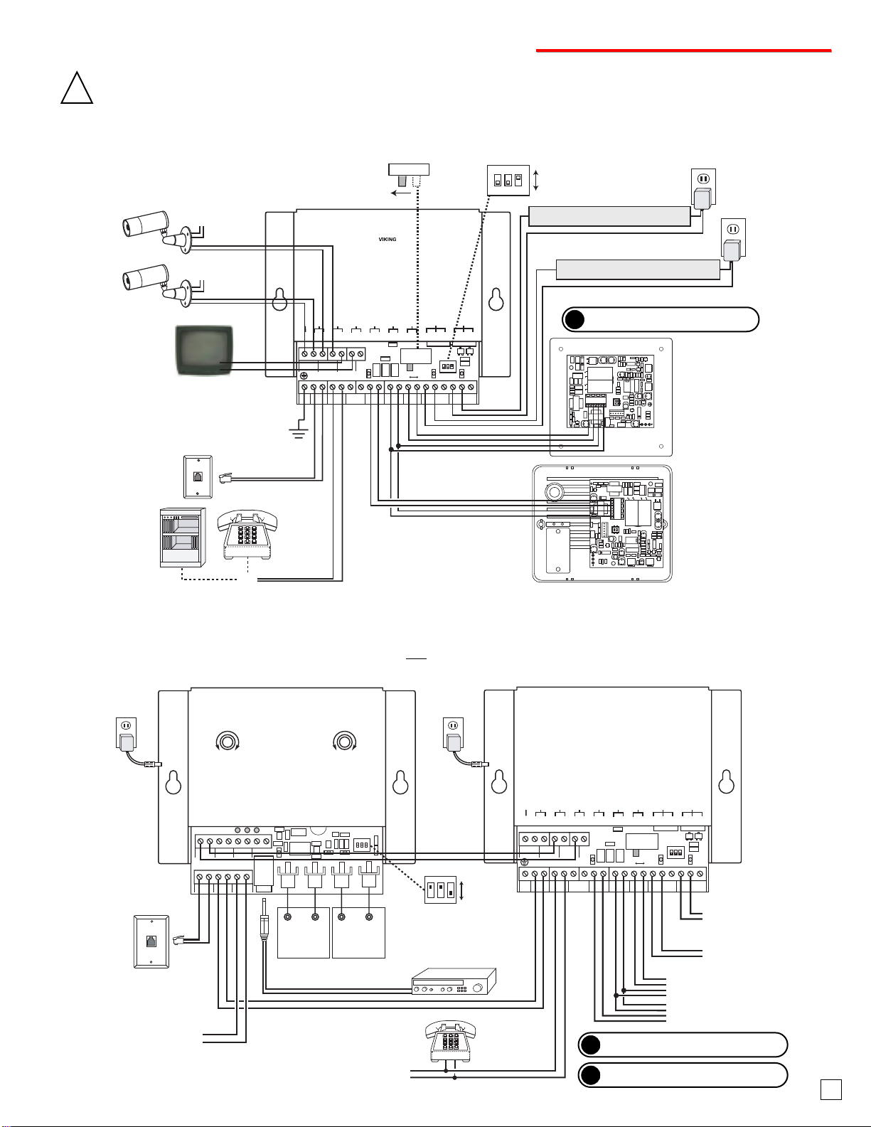
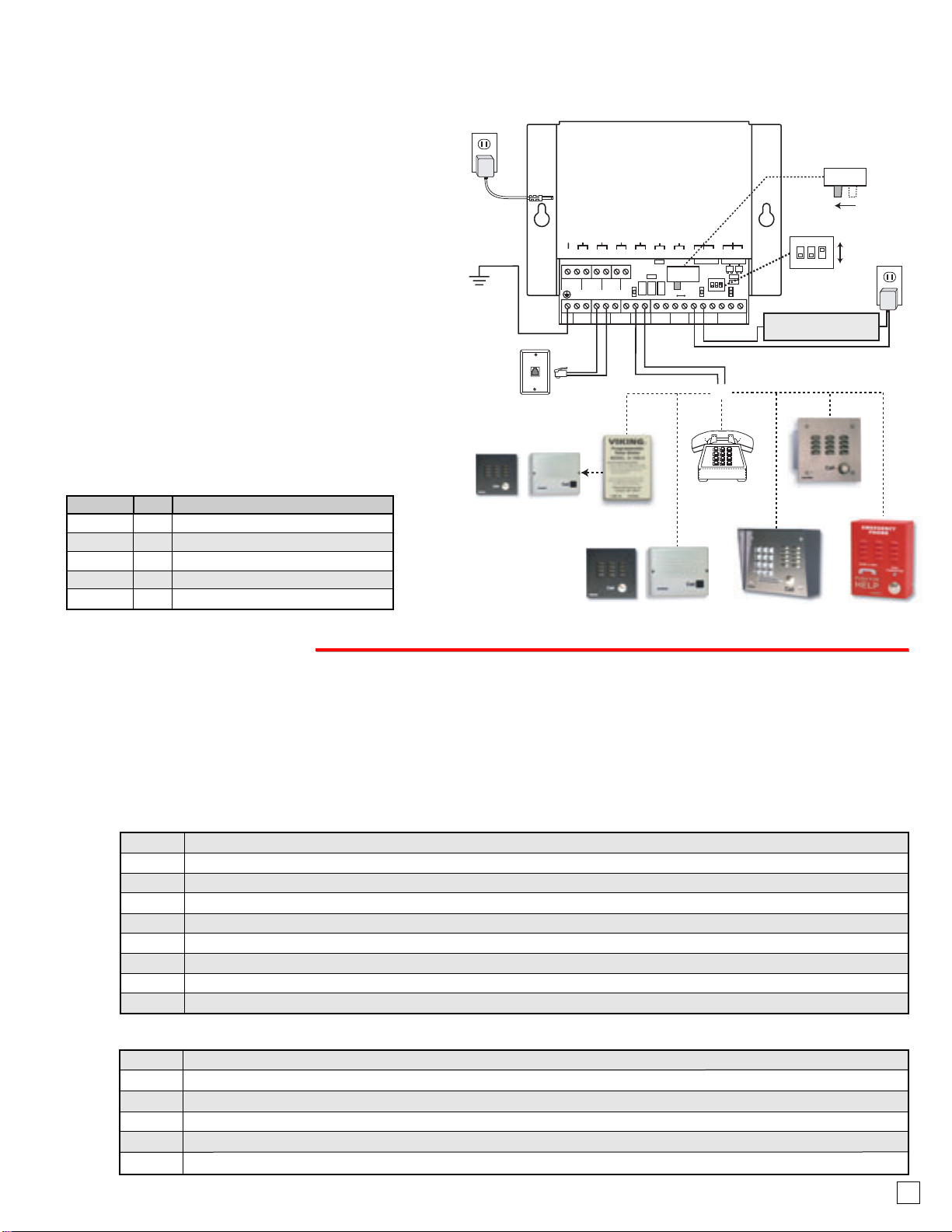
* Note: To increase surge protection, fasten a wire
from the screw terminal to Earth Ground (grounding
rod, water pipe, etc.)
Door Strike/Magnetic Locks: For
door strike/magnetic lock information,
contact your distributor or JLM
Wholesale at (800) 522-2940.
2
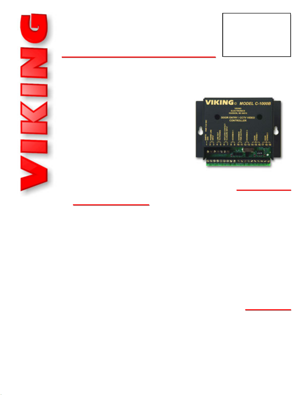
If trouble is experienced with the C-1000B, for repair or warranty information, please contact:
Viking Electronics, Inc., 1531 Industrial Street, Hudson, WI 54016 (715) 386-8666
If the equipment is causing harm to the telephone network, the telephone company may request that you disconnect the
equipment until the problem is resolved.
Connectionto Party Line Service issubjectto StateTariffs.Contactthestatepublic utility commission, public service com-
mission or corporation commission for information.
WHEN PROGRAMMING EMERGENCY NUMBERS AND (OR) MAKING TEST CALLS TO EMERGENCY NUMBERS:
Remain on the line and briefly explain to the dispatcher the reason for the call. Perform such activities in the off-peak
hours, such as early morning or late evenings.
It is recommended that the customer install anAC surge arrester in the AC outlet to which this device is connected.This
is to avoid damaging the equipment caused by local lightning strikes and other electrical surges.
PART 15 LIMITATIONS
This equipment has been tested and found to comply with the limits for a ClassAdigital device, pursuant to Part
15 of the FCC Rules. These limits are designed to provide reasonable protection against harmful interference
when the equipment is operated in a commercial environment. This equipment generates, uses, and can radi-
ate radio frequency energy and, if not installed and used in accordance with the instruction manual, may cause
harmful interference to radio communications. Operation of this equipment in a residential area is likely to cause
harmful interference in which case the user will be required to correct the interference at his own expense.
FCC REQUIREMENTS
This equipment complies with Part 68 of the FCC rules and the requirements adopted by the ACTA. On the side of this
equipment is a label that contains, among other information, a product identifier in the format US:AAAEQ##TXXXX. If
requested, this number must be provided to the telephone company.
The REN is used to determine the number of devices that may be connected to a telephone line. Excessive REN's on a
telephone line may result in the devices not ringing in response to an incoming call. In most but not all areas, the sum of
the REN's should not exceed five (5.0) To be certain of the number of devices that may be connected to a line, as deter-
mined by the total REN's, contact the local telephone company. For products approved after July 23, 2001, the REN for
this product is part of the product identifier that has the format US:AAAEQ##TXXXX. The digits represented by ## are the
REN without a decimal point (e.g., 03 is a REN of 0.3). For earlier products, the REN is separately shown on the label.
The plug used to connect this equipment to the premises wiring and telephone network must comply with the applicable
FCC Part 68 rules and requirements adopted by theACTA. If your home has specially wired alarm equipment connected
to the telephone line, ensure the installation of this C-1000B does not disable your alarm equipment. If you have ques-
tions about what will disable alarm equipment, consult your telephone company or a qualified installer.
If the C-1000B causes harm to the telephone network, the telephone company will notify you in advance that temporary
discontinuance of service may be required. But if advance notice isn't practical, the telephone company will notify the cus-
tomer as soon as possible.Also, you will be advised of your right to file a complaint with the FCC if you believe it is nec-
essary.
The telephone company may make changes in its facilities, equipment, operations, or procedures that could affect the
operation of the equipment. If this happens, the telephone company will provide advance notice in order for you to make
the necessary modifications to maintain uninterrupted service.

VIKING©MODEL SLP-1
DOOR BELL
SW. INPUT
LOUD RING
ENABLE
- +
I.O. COM.
ON
1 2 3
SINGLE LINE
PAGING CONTROLLER
PWR 13.8 VAC
VIKING
ELECTRONICS
HUDSON, WI 54016
AUDIO
INPUT
L R
AUDIO
OUTPUT
L R
MUSIC
ON
HOLD
INPUT
2 WATT
AMP GAIN
MIN MAX
PREAMP
VOLUME
MIN MAX
PWR PAGE MUTE
PAGE TRIG. OUT
C.O. LINE
INPUT
OUT TO
PHONES
- SPKR +
OUTPUT
LLRR
- +
13.8V AC
Adapter
(included)
120V AC
C.O. / Phone Line
Music On Hold
Source (Radio)
1/8" (3.5mm) Double Ended
Audio Cord (included)
DOOR ENTRY / CCTV VIDEO
/ PAGING CONTROLLER
VIKING©MODEL C-1000B
PWR 13.8 VAC
DOOR
STRIKE 1
DOOR
STRIKE 2
DOORBOX 2
DOORBOX
PWR OUTPUT
DOORBOX 1
123456789
10 11 12 13 14 15 16 17 18 19
EARTH
GND
PHONE LINE
INPUT
LINE OUT
TO PHONES
KEYLESS CONTACT
CLOSURE INPUT
VIKING
ELECTRONICS
HUDSON, WI 54016
EARTH
GND
C.O. LINE
INPUT
OUT TO
PHONES
KEYLESS
C.C. INPUT
DOOR
BOX 1
DOORBOX
13VAC PWR
DOOR
BOX 2
N.O. COM N.C.
DOOR STRIKE 1
SIG GND
VIDEO 1 IN
SIG GND
VIDEO 2 IN
SIG GND
VIDEO OUT
N.O. COM N.C.
DOOR STRIKE 2
TALK BATTERY
OFF ON
C
LED1
C
LED2
C
LED3
ON
1 2 3
COM N.O. N.C. - - - - AUX.
CONTACT
OUTPUT
Standard
Analog
Phone
To Doorstrike/
Magnetic Lock 2
To Doorstrike/
Magnetic Lock 1
To Additional Standard
Analog Phones
Main Out Input
L R L R
Pre-Amp
(Background
Music Source)
Power
Amplifier
To Viking Doorbox 1
(Front Door)
To Viking Doorbox 2
(Back Door)
13.8V AC
Adapter
(included)
120V AC
DIP Switch 2
must be ON
ON
OFF
1 2 3
ON
Up to (3) 8 Ohm
Speakers or Paging
Horns (optional)
A. One or Two Doorboxes Sharing a Phone Line and Controlling Two Optional Cameras
DOOR ENTRY / CCTV VIDEO
CONTROLLER
VIKING©MODEL C-1000B
PWR 13.8 VAC
DOOR
STRIKE 1
DOOR
STRIKE 2
DOORBOX 2
DOORBOX
PWR OUTPUT
DOORBOX 1
123456789
10 11 12 13 14 15 16 17 18 19
EARTH
G
ND
PH
O
NE LINE
INPUT
L
INE OUT
T
O
PH
O
NE
S
K
EYLESS CONTACT
C
L
OSU
RE INP
U
T
ELE
C
TR
O
NI
CS
HUD
SO
N, WI
5
4
0
1
6
EARTH
GND
C.O. LINE
INPUT
OUT TO
PHONES
KEYLESS
C.C. INPUT
DOOR
BOX 1
DOORBOX
13VAC PWR
DOOR
BOX 2
N.O. COM N.C.
DOOR STRIKE 1
SIG GND
VIDEO 1 IN
SIG GND
VIDEO 2 IN
SIG GND
VIDEO OUT
N.O. COM N.C.
DOOR STRIKE 2
TALK BATTERY
OFF ON
C
LED1
C
LED2
C
LED3
ON
1 2 3
COM N.O. N.C. - - - - AUX.
CONTACT
OUTPUT
or
Standard
Analog
Phones
Unused
Trunk Input
of PABX/KSU
(Set C-1000B
"Talk Battery"
switch to ON)
Talk Battery Switch
OFF ON
C.O. Line
Doorstrike/Magnetic Lock 2
5A@30V DC/250V AC maximum
Earth Ground
(see Page 2)
Doorbox 1
Back View of the
W-2000A or W-2000A-EWP
(not included)
Doorbox 2
Back View of the
W-1000 or W-1000-EWP
(not included)
120V AC
Doorstrike/Magnetic Lock 1
5A@30V DC/250V AC maximum
120V AC
Ground
Signal
**CCTV Camera 1
(not included)
Ground
Signal
**CCTV Camera 2
(not included)
Signal
Ground
**TV, Video Monitor,
VCR Recorder or
RF Modulator
(not included)
*Power
*Power
ON
1 2 3
DIP Switches
ON
OFF
See Operation, section A.
Note: Over 100ft power
runs require separate
doorbox power adapters.
?Need More Information on Doorboxes?
Call (715) 386-4345 and select 170.
* Note: Use the power supply
recommended and/or supplied
by the camera manufacturer.
I
In
ns
st
ta
al
ll
la
at
ti
io
on
na
an
nd
dA
Ap
pp
pl
li
ic
ca
at
ti
io
on
ns
s
** Note: The C-1000B must be programmed
with (
4
8) to control cameras. In the CCTV
video control mode (
4
8), Auxiliary Contact
Mode is disabled.
IMPORTANT: Electronic devices are susceptible to lightning and power station electrical surges from both the AC outlet and the
telephone line. It is recommended that a surge protector be installed to protect against such surges. Contact Panamax at (800)
472-5555 or Electronic Specialists Inc. at (800) 225-4876.
!
B. Provide Paging, Doorbox, and Doorstrike Control with Unique Front and Back Door Chimes
3
?Need More Information on the SLP-1?
Call (715) 386-4345 and select 478.
?Need More Information on Doorboxes?
Call (715) 386-4345 and select 170.
Note: To provide unique front and back door chimes, the C-1000B must be programmed to enable the “Auxiliary Contact Mode” (
4
7) and have the auxiliary contact pro-
grammed for custom ring cadence (12#03). Doorbox ringing can also be disabled by placing the C-1000B in the “Doorbell Mode” (
4
1). See the C-1000B Technical Practice
for programming details. The C-1000B CCTV Video Control Mode can NOT be used in conjunction with unique front and back door chimes. See Operation section I,
page 7. If CCTV video control is required, a Viking VC-1000 can be used. The caller’s music on hold is limited to 5 seconds while communicating with a doorbox.

Step 1. Connect the power, required doorboxes, and doorstrike outputs
(if required) as shown in section A.
Step 2. Connect an analog phone or unused PABX/KSU trunk port to
terminals 4& 5, “LINE OUT TO PHONES” on the C-1000B.
Step 3. Be sure the “Talk Battery Switch” is in the ON position.
DOOR ENTRY / CCTV VIDEO
/ PAGING CONTROLLER
VIKING©MODEL C-1000B
PWR 13.8 VAC
DOOR
STRIKE 1
DOOR
STRIKE 2
DOORBOX 2
DOORBOX
PWR OUTPUT
DOORBOX 1
123456789
10 11 12 13 14 15 16 17 18 19
EARTH
GND
PHONE LINE
INPUT
LINE OUT
TO PHONES
KEYLESS CONTACT
CLOSURE INPUT
VIKING
ELECTRONICS
HUDSON, WI 54016
EARTH
GND
C.O. LINE
INPUT
OUT TO
PHONES
KEYLESS
C.C. INPUT
DOOR
BOX 1
DOORBOX
13VAC PWR
DOOR
BOX 2
N.O. COM N.C.
DOOR STRIKE 1
SIG GND
VIDEO 1 IN
SIG GND
VIDEO 2 IN
SIG GND
VIDEO OUT
N.O. COM N.C.
DOOR STRIKE 2
TALK BATTERY
OFF ON
C
LED1
C
LED2
C
LED3
ON
1 2 3
COM N.O. N.C. - - - - AUX.
CONTACT
OUTPUT
Doorbell
(not included)
Not to Exeed: .5A @ 125V AC
or 1A @ 30V DC
ON
1 2 3
DIP Switches
ON
OFF
The C-1000B can be used as a line concentrator, allowing up to three separate C.O. lines to connect to one telecom
device. For more information: call 715-386-4345 and select 872.
The C-1000B can also be used without a C.O. line. This is ideal
for connecting the C-1000B to an unused trunk/line input of your
phone system or connecting to phones used only for doorbox com-
munication.
DOOR ENTRY / CCTV VIDEO
/ PAGING CONTROLLER
VIKING©MODEL C-1000B
PWR 13.8 VAC
DOOR
STRIKE 1
DOOR
STRIKE 2
DOORBOX 2
DOORBOX
PWR OUTPUT
DOORBOX 1
123456789
10 11 12 13 14 15 16 17 18 19
EARTH
GND
PHONE LINE
INPUT
LINE OUT
TO PHONES
KEYLESS CONTACT
CLOSURE INPUT
VIKING
ELECTRONICS
HUDSON, WI 54016
EARTH
GND
C.O. LINE
INPUT
OUT TO
PHONES
KEYLESS
C.C. INPUT
DOOR
BOX 1
DOORBOX
13VAC PWR
DOOR
BOX 2
N.O. COM N.C.
DOOR STRIKE 1
SIG GND
VIDEO 1 IN
SIG GND
VIDEO 2 IN
SIG GND
VIDEO OUT
N.O. COM N.C.
DOOR STRIKE 2
TALK BATTERY
OFF ON
C
LED1
C
LED2
C
LED3
ON
1 2 3
COM N.O. N.C. - - - - AUX.
CONTACT
OUTPUT
or
Standard
Analog
Phones
Unused
Trunk Input
of PABX/KSU
Talk Battery Switch
OFF ON
ON
1 2 3
DIP Switches
ON
OFF
DOOR ENTRY / CCTV VIDEO
/ PAGING CONTROLLER
VIKING©MODEL C-1000B
PWR 13.8 VAC
DOOR
STRIKE 1
DOOR
STRIKE 2
DOORBOX 2
DOORBOX
PWR OUTPUT
DOORBOX 1
123456789
10 11 12 13 14 15 16 17 18 19
EARTH
GND
PHONE LINE
INPUT
LINE OUT
TO PHONES
KEYLESS CONTACT
CLOSURE INPUT
VIKING
ELECTRONICS
HUDSON, WI 54016
EARTH
GND
C.O. LINE
INPUT
OUT TO
PHONES
KEYLESS
C.C. INPUT
DOOR
BOX 1
DOORBOX
13VAC PWR
DOOR
BOX 2
N.O. COM N.C.
DOOR STRIKE 1
SIG GND
VIDEO 1 IN
SIG GND
VIDEO 2 IN
SIG GND
VIDEO OUT
N.O. COM N.C.
DOOR STRIKE 2
TALK BATTERY
OFF ON
C
LED1
C
LED2
C
LED3
ON
1 2 3
COM N.O. N.C. - - - - AUX.
CONTACT
OUTPUT
STAND-ALONE
DOOR CONTROLLER
ENTRY SYSTEM
VIKING
PROGRAM
PHONE
GANG
PROG
COMM
ELECTRONICS
HUDSON, WI 54016
VIKING©MODEL ES-1
POWER 12 VDC
BLK
RED
GRN
WHT
ENTRY POINT
WIEGAND
DEVICE
LOG
BUS
Keyed Momentary Switch/
Postal Lock with Limit
Switch (not included) Viking HID-1
Proximity Card
Reader (not included)
Viking HID-2
Keypad
(not included)
and/or
and/or
ON
1 2 3
DIP Switches
ON
OFF
D. Using the C-1000B with Keyless Entry, Proximity Card Reader or a Postal Lock Switch
C. Using a C-1000B without a C.O. Line
E. Using the C-1000B to Trigger a Doorbell
Step 1. Connect a device that can provide a
momentary contact closure, such as
the Viking ES-1 with HID-1 Card
Reader or HID-2 Keypad, keyed
switch, postal lock with limit switch,
etc. to terminals 6& 7, “KEYLESS
CONTACT CLOSURE INPUT”.
Step 2. Connect doorboxes and doorstrike
outputs (if required) as shown in
section A.
Step 3. See Operation section A,5. Keyless
Entry/Postal Lock.
Step 1. Connect the doorbell (not included) as shown to the right.
Note: The C-1000B will not supply power to the doorbell,
a power adapter is necessary.
Step 2. Connect doorboxes and doorstrike outputs (if required)
as shown in section A.
Step 3. Program the Auxiliary Contact Output as desired (see
Programming section B).
Step 4. See Operation section A, 6. Auxiliary Contacts.
F. Line Concentrator Mode (One Telecom Device Can Answer up to Three Lines)
?Need More Information on the HID-1?
Call (715) 386-4345 and select 197.
?Need More Information on the ES-1?
Call (715) 386-4345 and select 193.
?Need More Information on the HID-2?
Call (715) 386-4345 and select 199.
4
G. Using the C-1000B with Three Doorboxes and No C.O. Line
The C-1000B can be used to control up to three doorboxes. For more information: call 715-386-4345 and select 872.

H. Using the C-1000B on an Analog Station Port (Analog PABX/KSU Station Mode)
Note: This mode can NOT be used with W-1000, W-2000A or W-3000 doorboxes.This application is ideal for connecting the
C-1000B to an unused analog station of your phone system. See Programming section Fand Operation section A.
DOOR ENTRY / CCTV VIDEO
CONTROLLER
VIKING©MODEL C-1000B
PWR 13.8 VAC
DOOR
STRIKE 1
DOOR
STRIKE 2
DOORBOX 2
DOORBOX
PWR OUTPUT
DOORBOX 1
123456789
10 11 12 13 14 15 16 17 18 19
EARTH
GND
PHONE LINE
INPUT
LINE OUT
TO PHONES
KEYLESS CONTACT
CLOSURE INPUT
VIKING
ELECTRONICS
HUDSON, WI 54016
EARTH
GND
C.O. LINE
INPUT
OUT TO
PHONES
KEYLESS
C.C. INPUT
DOOR
BOX 1
DOORBOX
13VAC PWR
DOOR
BOX 2
N.O. COM N.C.
DOOR STRIKE 1
SIG GND
VIDEO 1 IN
SIG GND
VIDEO 2 IN
SIG GND
VIDEO OUT
N.O. COM N.C.
DOOR STRIKE 2
TALK BATTERY
OFF ON
C
LED1
C
LED2
C
LED3
ON
1 2 3
COM N.O. N.C. - - - - AUX.
CONTACT
OUTPUT
13.8V AC
Adapter
included
120V AC
or
Standard
Analog Phone
K-1900-5
Dialer
* K-1700-3
Phone
E-1600A
Phone
Talk Battery Switch
OFF ON
CO line or
Analog
PABX/KSU
station
E-30
Speaker Phone
Earth
Ground
(see pg 2)
E-10 or E-20A
Speaker Phones
E-10 or E-20A
Speaker Phones
5A@30V DC/
250V AC maximum
120V AC
Doorstrike/
Magnetic Lock 2
ON
1 2 3
DIP Switches
ON
OFF
Model
E-10/E-20A
E-30
E-1600A
K-1700-3
K-1900-5
Fax #
210
212
215
157
317
Description
Handsfree Speaker Phone
Vandal Resistant Handsfree Speaker Phone
Emergency/Elevator Phone
Handsfree Speaker Phone with Keypad
Touch Tone Dialer
Need more information on the products shown to the right?
Call 715-386-4345 and enter the fax number below:
Note: The E-10 and E-20A
Speaker Phones may be used
without a dialer when installed
on a ring-down circuit.
Notes:
*1. The K-1700-3’s keypad can be used for extension
dialing, etc., but can NOT be used for keyless entry
(see Installation and Applications section D).
2. If “Switched” camera control is needed (for a switch-
ing video RF modulator), connect the camera to
“Video 2 In”, connect the RF Modulator to “Video Out”
and program the C-1000B with “ 47 “ and “ 11 # 03”.
3. Once the “Analog PBX/KSU Station Mode” (45) has
been programmed, you are not able to access the
programming mode of the C-1000B in the normal
fashion. For details, see Programming, Section A.
5
Important:
1. In this application, only a single door phone is used
and
4
5must be selected when in programming.
2. Do not program the CCTV Video Control Mode (48)
in this application (See Note 2 below). Only Auxiliary
Contact Mode (47) can be used.
P
Pr
ro
og
gr
ra
am
mm
mi
in
ng
g
A. Accessing the Programming Mode
1. Accessing the Programming Mode Locally (Security Code Bypass Mode)
Follow Sections 1or 2to program a new C-1000B or any C-1000B that has not been previously programmed into the “Analog
PBX/KSU Station Mode” (45). If the “Analog PBX/KSU Station Mode” has been programmed, follow Sections 3or 4to access pro-
gramming.
Note: If you are not sure how the C-1000B was previously programmed and have difficulty accessing the programming mode by
following Sections 1 or 2, follow Sections 3 or 4 in case the C-1000B is currently in the “Analog PBX/KSU Station Mode” (
4
5).
Step 1. Disconnect the PHONE LINE INPUT.
Step 2. Slide the TALK BATTERY switch to the ON position.
Step 3. Move DIP switch 2 from OFF to ON (see Programming section E).
Step 4. Come off-hook with a phone connected to terminals 4& 5,LINE OUT TO PHONES.
Step 5. A double beep will indicate that you have accessed the programming mode.
Step 6. You can now Touch Tone program the features listed in section Bbelow.
Step 7. When finished programming, hang up and move DIP switch 2 to the OFF position.
Step 8. Slide the TALK BATTERY switch back to the OFF position.
Step 9. Reconnect line to PHONE LINE INPUT.
2. Accessing the Programming Mode Remotely
Step 1. Call into the C-1000B from a Touch Tone phone.
Step 2. Answer the call using the phone (device) connected to terminals 4& 5, LINE OUT TO PHONES.
Step 3. From either phone enter 4followed by the security code (factory set to 845464, see Programming section D).
Step 4. A double beep will indicate that you have accessed the programming mode.
Step 5. You can now Touch Tone program the features listed in section Bbelow.
Step 6. When finished, hang up both phones to exit the programming mode
Note: Programming from a cell-phone may not be suitable in areas with weak coverage.

3. Accessing the Programming Mode Locally (When 45 mode has been programmed)
Enter
03 #01
12 #03
42
To Program the C-1000B...
1. ...to set door strike 1 to activate for 3 seconds
2. ...to set the auxiliary contacts to activate an external ringer or strobe light in a custom ring cadence while
either doorbox is ringing
3. ...to have doorboxes ring phones in a custom ring pattern
B. Quick Programming Features Memory
Location
Enter Digits - then -
Door strike 1 activation time .5 - 10 seconds (00 = .5 seconds/factory default) ....................
Door strike 2 activation time .5 - 10 seconds (00 = .5 seconds/factory default) ....................
Security Code (factory set to 845464) ....................................................................................
Disable special modes (41 - 46 and 48) listed below (factory default) ...............................
* Doorbell mode .....................................................................................................................
* Custom ring mode ................................................................................................................
* Multiple relay activation mode .............................................................................................
* Paging mode (not for use with SLP-1, see Programming, Section F) ...............................
*Analog PABX/KSU station mode ..........................................................................................
* Inhibit latching commands mode .........................................................................................
Auxiliary contact mode (disables CCTV video control mode, factory default) .................
Auxiliary contact activation time .5 - 10 seconds (00 = .5 seconds/factory default)........
Auxiliary contact latched while either doorbox is activated .............................................
** Auxiliary contact activated in custom ring cadence ......................................................
**CCTV video control mode (disables auxiliary contact mode) .........................................
CCTV Inactive (Idle State) Modes:
Camera 1 and 2 output disconnected (factory default) ............................................
Output camera 1 ......................................................................................................
Continue to output video from last camera activated ..............................................
Sequenced video from camera 1 and 2 (rotates every 4 seconds) .........................
To reset to factory settings .....................................................................................................
* Note: Multiple modes may be selected.
** Note: Not compatible with Analog PABX/KSU Station mode.
+
+
+
+
+
+
+
+
+
+
#01
#02
#47
#03
#03
#03
#04
#04
#04
#04
2 digits (00-10)
2 digits (00-10)
6 digits (0-9)
40
41
42
43
44
45
46
47
2 digits (00-10)
11
12
48
01
02
03
04
###
6
IMPORTANT: Only use Sections 3 or 4 when the C-1000B has previously been programmed into the “Analog
PBX/KSU Station Mode” (
4
5)
Step 1. Connect a PBX/KSU analog extension (or phone line) to terminals 4& 5, LINE OUT TO PHONES.
Step 2. Slide the TALK BATTERY switch to the OFF position.
Step 3. Move DIP switch 2 from OFF to ON (see Programming section E).
Step 4. Come off-hook with a phone connected to terminals 8& 9 DOORBOX 1.
Step 5. PBX/KSU dial tone will be heard along with a double beep from the C-1000B to indicate that you have
accessed the programming mode.
Step 6. You can now Touch Tone program the features listed in section Bbelow. (ignore busy signals, reorder tones or
intercept messages heard while programming).
Step 7. When finished programming, hang up and move DIP switch 2 to the OFF position.
4. Accessing the Programming Mode Remotely (When 45 mode has been programmed)
Note: To access programming in this fashion, there must be a PBX/KSU analog extension (or phone line) connected to termi-
nals 4& 5, LINE OUT TO PHONES and the TALK BATTERY switch must be set to OFF.
C. Programming Examples
Step 1. From another extension or phone line, call into the PBX/KSU analog extension (or phone line)
connected to terminals 4& 5, LINE OUT TO PHONES.
Step 2. Answer the call using the phone (or device) connected to terminals 8& 9, DOORBOX 1.
Step 3. From the remote phone enter 4followed by the six digit security code (factory set to 845464, see
programming Section D).
Step 4. A double beep will indicate that you have accessed the programming mode.
Step 5. You can now Touch Tone program the features listed in section Bbelow.
Step 6. When finished programming, hang up both phones.

D. Security Code
DIP Switches shown
in the factory default
positions
DOOR ENTRY / CCTV VIDEO
/ PAGING CONTROLLER
VIKING©MODEL C-1000B
PWR 13.8 VAC
DOOR
STRIKE 1
DOOR
STRIKE 2
DOORBOX 2
DOORBOX
PWR OUTPUT
DOORBOX 1
123456789
10 11 12 13 14 15 16 17 18 19
EARTH
GND
PHONE LINE
INPUT
LINE OUT
TO PHONES
KEYLESS CONTACT
CLOSURE INPUT
VIKING
ELECTRONICS
HUDSON, WI 54016
EARTH
GND
C.O. LINE
INPUT
OUT TO
PHONES
KEYLESS
C.C. INPUT
DOOR
BOX 1
DOORBOX
13VAC PWR
DOOR
BOX 2
N.O. COM N.C.
DOOR STRIKE 1
SIG GND
VIDEO 1 IN
SIG GND
VIDEO 2 IN
SIG GND
VIDEO OUT
N.O. COM N.C.
DOOR STRIKE 2
TALK BATTERY
OFF ON
C
LED1
C
LED2
C
LED3
ON
1 2 3
COM N.O. N.C. - - - - AUX.
CONTACT
OUTPUT
ON
OFF 1 2 3
ON
Switch
1
1
2
2
3
3
E. Dip Switch Programming
Position
OFF
ON
OFF
ON
OFF
ON
Description
Doorstrike Activation = 0.5 seconds (factory setting)
Doorstrike Activation = 10 seconds
Normal Mode (factory setting)
Security Code Bypass Mode
Line Concentrator Mode
Normal Operation (factory setting)
This six digit number can be used to access the programming mode. The security code has been factory set to 845464 (V-I-K-I-N-
G). It is recommended that you change the security code to a personal 6 digit number. To change the security code, access pro-
gramming (see Programming section A). Enter six digits 0-9 followed by #47. If you have forgotten your security code, follow the
steps in Programming section A, 1. Accessing the Programming Mode Locally. Note: The security code must be six digits in
length and can NOT contain a
4
or #.
F. Mode Descriptions
Entering these codes while in programming will switch the C-1000B into the corresponding mode.
Disable Special Modes (40): This command disables (clears) all the special modes listed below. Enter this command before pro-
gramming the rest of the selections to be sure no unwanted modes are set.
Doorbell Mode (41): In this mode, the ring signal from either doorbox is prevented from going through to the “LINE OUT TO
PHONES“ terminals. This is useful when a conventional door bell is connected to the auxiliary contacts. Now when someone acti-
vates a doorbox, the doorbell will chime rather than the phone ringing (see Programming section B).
Custom Ring Mode (42): With this mode selected, the ring signal from the device ports are interrupted in a double burst pattern,
making it easier to determine if the incoming call is from a doorbox or the C.O. line. Note: Some telephones and phone systems
are not compatible with this feature.
Multiple Relay Activation Mode (43): If selected, after a door strike command is entered, the phone is switched back to the door-
box port so additional doorstrike (relay activation) commands can be entered. This is useful when letting someone through your
gate with the first command then unlocking your front doorstrike with a second command. To return to the call on hold, enter “#”.
Paging Mode (44): This mode is used for basic paging and/or existing installations using a C-1000B with Viking paging amplifier
models: PA-2A, CPA-7B or PI-1. For more information, retrieve Fax Back Document 872. This mode is NOT for use with model SLP-
1. For single line paging applications, the SLP-1 is recommended, see Installation section Band retrieve Fax Back Document 478.
Analog PABX/KSU Station Mode (45): This mode is ideal when installing the C-1000B on a phone system that does not have a
spare trunk port but does have an unused analog station port. This mode allows any standard (POTS) telephone such as the E-10,
E-20A, E-30 or K-1700-3 to be used in place of Doorbox 1. Only one door phone can be used in this mode. When the door phone
goes off-hook, a hot-line dialer or ringdown station will call the desired phone system extension. The phone on that extension can
then communicate with the door phone and activate doorstrikes as needed. Note: Only a single door phone may be used. Multiple
relay activation cannot be used with Viking door phone models E-10, E-20A, E-30 or K-1700-3.
Inhibit Latching Commands Mode (46): In some installations it is critical that the door strike or door actuator not be turned on for
long periods of time. To prevent this from happening, enter 46when in programming. In this mode, the toggle command (4#) and
the continuous activation command (41) are ignored.
Auxiliary Contact Mode (47): See Operation section 6, page 8.
CCTV Video Control Mode (48): In this mode the C-1000B allows two CCTV video cameras to be concentrated down to one video
signal, by switching to the camera at the zone/entry point being used. When the C-1000B detects a doorbox ringing or when a door-
box is monitored, it will connect that camera’s video feed to the video output. When both doorboxes are inactive (idle), the C-1000B
can be programmed to do one of four operations (see Operation, Section C, page 8). Note: The CCTV Video Control Mode (
4
8)
is disabled when using the Auxiliary Contact Mode (
4
7).
O
Op
pe
er
ra
at
ti
io
on
n
A. Doorbox Controller
Avisitor pressing the “Call” button will cause the phones connected to the “LINE OUT TO PHONES“ terminals to ring. Simply
answer your phone to converse with the visitor. After answering the call, a single or double beep will be heard in the phone,
indicating which doorbox has called - a single beep for doorbox 1 and a double beep for doorbox 2.
1. Communicating with the Doorbox
a. Visitor Initiated Call
A doorbox may be monitored from any phone connected to the C-1000B by Touch Tone dialing a “#” followed by a Touch
Tone “1” or “2” to monitor doorbox 1 or doorbox 2 respectively. This feature is not available for pulse dialing phones. Note:
Do not attempt doorbox monitoring while a call is in progress, the call will be disconnected. Note: When monitor-
ing, the auxiliary contact will only work in the Continuous Mode (11 # 03).
b. Monitoring Doorboxes
7

8
If a C.O. line call is in progress and a doorbox is activated, a single or double “call waiting” tone will be heard indicating doorbox
1 or doorbox 2 is calling. To place the in-progress call on hold and answer the calling doorbox, simply dial a Touch Tone “#”,
pulse dial a “2” or hook flash twice.
2. Placing C.O. Line Calls on Hold
To activate a relay contact, you must be communicating with a doorbox. Touch Tone dial “44”, pulse dial a “3” or hook flash three
times. Two confirmation tones will be heard and the relay will be activated for the programmed doorstrike activation time. The
phone will then be returned to the C.O. line. If a call was in progress, the original caller will be taken off hold to continue the con-
versation. To return to the original call without activating a relay, Touch Tone dial “#”, pulse dial a “2” or hook flash twice.
3. Activating a Doorstrike, Magnetic Lock or Gate Controller
Momentarily activate doorstrike relay 1 or 2 .........................................
Continuously activate (latch) doorstrike relay 1 or 2 .............................
Continuously de-activate (unlatch) doorstrike relay 1 or 2 ...................
Activate opposite doorstrike relay ........................................................
Toggle relay from last position ..............................................................
Answer or disconnect a doorbox call ....................................................
Monitor doorbox 1 ................................................................................
Monitor doorbox 2 ................................................................................
* Pulse Dial/Flash Commands
44 Pulse dial 3 or hook flash 3 times
41
40
42
4#
# Pulse dial 2 or hook flash 2 times
# 1
# 2
Touch Tone Commands
4. Features
Note: When on the C.O. line, if a Touch Tone other than #is entered, any additional Touch Tones in that dial string will be ignored. To regain
control of the C-1000B, the phone must be momentarily placed on-hook.
* Note: Pulse dialing and flash commands are not compatible in the “Multiple Relay Activation” mode.
5. Keyless Entry/Postal Lock
6. Auxiliary Contact Mode (47)
The auxiliary contacts are a separate set of contacts that can be programmed (see Programming section B) to activate in dif-
ferent patterns when doorbox 1 or doorbox 2 is activated. A momentary activation, a continuous activation while the doorbox is
in use, and a ring cadence pattern are available. Note: The auxiliary contact mode (47) is disabled when using the CCTV Video
Control Mode (48).
If an auxiliary contact activation time is programmed (two digits 00-10 followed by #03), when either doorbox is activated, the
auxiliary contacts will activate for the programmed time (.5 - 10 seconds). This is ideal for operating a doorbell or chime.
a. Timed Activation
If the auxiliary contact is programmed to continuously activate (11 followed by #03), while either doorbox is ringing or in use,
the auxiliary contacts will latch. This is ideal for controlling lights, etc.
b. Continuous Activation
If the auxiliary contact is programmed to custom ring cadence (“12 #03”) when doorbox 1 is activated, a repeating 1 second
on and 3 seconds off contact pattern is generated. If doorbox 2 is activated, a repeating double burst contact pattern is gen-
erated with 3 seconds off between patterns. Note: Ring cadence activation is not compatible with the Analog PABX/KSU
Station mode.
c. Ring Cadence Activation
When a momentary postal lock contact closure is made across terminals 6& 7(see Installation section D), the doorstrike 1 con-
tact will activate for the programmed time.
The C-1000B allows two CCTV video cameras to be concentrated down to one video signal, by switching to the camera at the
zone/entry point being used. When the C-1000B detects doorbox ringing or when a doorbox is monitored it will connect that camera’s
video feed to the video output. This happens in a first come, first serve manner. When both doorboxes are inactive (idle) the C-1000B
can be programmed to do one of four operations (See Programming, Section B, Page 6):
1. Disconnect all cameras so there is no video output. This mode is very convenient when used in combination with a switching video
RF modulator (Radio Shack part # 15-1214 or equivalent), which automatically switches the video source in when a video signal
is present. A home TV’s broadcast/satellite program will be automatically interrupted to show video feed of the arriving guest (see
Installation section A).
2. Connect video feed from camera 1.
3. Remain connected to the camera near the last doorbox activated and continue feeding video, until the other doorbox is activated.
4. Sequence video from both cameras, rotating every 4 seconds.
Note: The CCTV Video Control Mode (48) is disabled when using the Auxiliary Contact Mode (47).
B. Doorbox Triggered CCTV Camera Switching / CCTV Video Control Mode ( 48)
Due to the dynamic nature of the product design, the information contained in this document is subject to change without notice. Viking Electronics, and its affiliates and/or subsidiaries assume no respon-
sibility for errors and omissions contained in this information. Revisions of this document or new editions of it may be issued to incorporate such changes.
Fax Back Doc 168
ZF302010 Rev A
Printed in the U.S.A.
P
Pr
ro
od
du
uc
ct
tS
Su
up
pp
po
or
rt
tL
Li
in
ne
e.
..
..
.7
71
15
5.
.3
38
86
6.
.8
86
66
66
6F
Fa
ax
xB
Ba
ac
ck
kL
Li
in
ne
e.
..
..
.7
71
15
5.
.3
38
86
6.
.4
43
34
45
5
Other manuals for C-1000B
11
This manual suits for next models
7
Table of contents
Other Viking Security System manuals

Viking
Viking RC-2A Installation and operating instructions

Viking
Viking 1600A Series Instructions for use

Viking
Viking VS 2625 User manual

Viking
Viking VS 1125 Original operating instructions

Viking
Viking PROXCARD User manual

Viking
Viking DVA-TNT Instructions for use

Viking
Viking K-2000-DVA User manual

Viking
Viking VS 1125 Installation instructions

Viking
Viking PROXCARD Instructions for use

Viking
Viking FIRECYCLE III User manual