Autronica AutroSense Micra 25 System manual

116-P-ASMICRA25/DE, Rev. D, 2017-05-02, Autronica Fire And Security AS
Installation handbook
High sensitivity aspirating smoke detector AutroSense Micra 25

Installation handbook, High sensitivity aspirating smoke detector AutroSense Micra 25,
116-P-ASMICRA25/DE, Rev. D, 2017-05-02,
Autronica Fire and Security
Page 2
COPYRIGHT ©
This publication, or parts thereof, may
not be reproduced in any form, by any
method, for any purpose.
Autronica Fire and Security AS and its
subsidiaries assume no responsibility
for any errors that may appear in the
publication, or for damages arising
from the information in it. No
information in this publication should
be regarded as a warranty made by
Autronica Fire and Security AS. The
information in this publication may be
updated without notice.
Product names mentioned in this
publication may be trademarks. They
are used only for identification.

Installation handbook, High sensitivity aspirating smoke detector AutroSense Micra 25, 116-P-ASMICRA25/DE, Rev. D, 2017-05-02,
Autronica Fire and Security
Table of Contents
1. Introduction......................................................................1
1.1 About the handbook ..........................................................................1
1.2 About the reader................................................................................1
1.3 Reference documentation.................................................................1
1.4 CE identification.................................................................................2
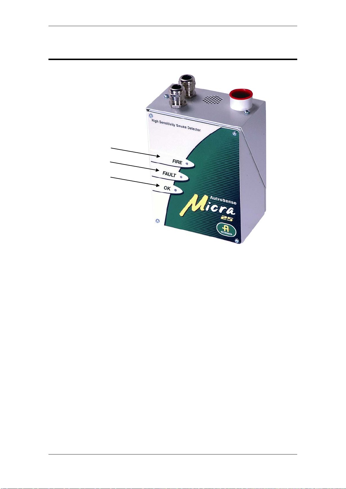
2. Indicators .........................................................................3
3. Inside the detector...........................................................4
3.1 Interior view.......................................................................................4
3.2 Detector terminal block connections .................................................5
4. Programming the detector..............................................6
4.1 Time and date – “Time and date” tab................................................7
4.2 Alarm levels – “Alarm levels and delays” tab, level subgroup...........7
4.3 Alarm delays – “Alarm levels and delays” tab, delay subgroup.........7
4.4 ClassiFire override- “Alarm levels and delays” tab............................7
4.5 Alarm factor – “Alarm levels and delays” tab.....................................7
4.6 LDD enable – “Alarm levels and delays” tab.....................................8
4.7 FastLearn enable – “Alarm levels and delays” tab............................8
4.8 Auto FastLearn enable – “Alarm levels and delays” tab....................9
4.9 ClassiFire 3D – “Alarm levels and delays” tab...................................9
4.10 Demo mode – “Alarm levels and delays” tab ....................................9
4.11 Day start/Night start – “Day/Night switching” tab...............................10
4.12 Disable day/night switching – “Day/Night switching” tab ...................10
4.13 Remote functions – “Alarm actions” tab, remote input subgroup......10
4.14 Programmed isolation – “Alarm actions” tab.....................................10
4.15 Latching alarms – “Alarm actions” tab...............................................11
4.16 Latching faults – “Alarm actions” tab.................................................12
4.17 Cascading alarms – “Alarm actions” tab ...........................................12
4.18 Device type – “Device information” tab..............................................12
4.19 Firmware version – “Device information” tab.....................................12
4.20 Run-time hours – “Device information” tab........................................12
4.21 Watchdog count – “Device unformation” tab.....................................12
4.22 Device text – “Device information” tab ..............................................13
4.23 Reference detector – “Referencing” tab............................................13
4.24 Reference enable – “Referencing” tab..............................................13
4.25 Reference level – “Referencing” tab..................................................13
4.26 Reference back-off – “Referencing” tab............................................13
4.27 Flow rate – “Flow monitoring” tab......................................................13
4.28 Flow high limit – “Flow monitoring” tab..............................................13
4.29 Flow low limit – “Flow monitoring” tab ...............................................13
4.30 Flow fault delay – Flow monitoring tab ..............................................14
4.31 Access code – “Miscellaneous” tab...................................................14
4.32 Chart log recording rates...................................................................15

Installation handbook, High sensitivity aspirating smoke detector AutroSense Micra 25,
116-P-ASMICRA25/DE, Rev. D, 2017-05-02,
Autronica Fire and Security
Page 2
4.33 Separator condition – “Miscellaneous” tab........................................15
4.34 Separator change date – “Miscellaneous” tab...................................16
4.35 Factory default – “Miscellaneous” tab................................................16
5. Other remote software features......................................17
5.1 Reset.................................................................................................17
5.2 Histogram screen..............................................................................17
5.3 Chart recording..................................................................................19
5.4 Load/save function settings...............................................................20
6. Sampling-pipe design......................................................21
6.1 Pipe work...........................................................................................22
6.2 EN 54-20 compliance........................................................................23
7. Installation........................................................................24
7.1 Docking station..................................................................................24
7.2 Mechanical installation ......................................................................25
7.3 Electrical installation..........................................................................25
7.3.1 Power-supply connections ......................................................25
7.4Final installation.................................................................................26
8. Interfacing........................................................................27
8.1 Setting the detector address..............................................................27
8.2 Connection to AutroSafe ...................................................................28
8.3 Connection to BS-systems................................................................28
8.4 Connecting to a PC ...........................................................................29
9. Event log ..........................................................................30
10.Commissioning................................................................32
10.1 Commissioning checklist...................................................................32
11.Maintenance.....................................................................33
11.1 Diagnostics........................................................................................33
12.Troubleshooting ..............................................................35
12.1 Nuisance alarms occur too often.......................................................35
12.2 Elevated smoke levels do not generate alarms.................................35
12.3 Low mean output...............................................................................35
12.4 Detector sensitivity varies over time..................................................35
12.5 Flow fault errors.................................................................................36
12.5.1"Low Flow" error messages ....................................................36
12.5.2"High Flow" error messages....................................................36
13.Dos and Don’ts ................................................................37
13.1 Do......................................................................................................37

Installation handbook, High sensitivity aspirating smoke detector AutroSense Micra 25, 116-P-ASMICRA25/DE, Rev. D, 2017-05-02,
Autronica Fire and Security
13.2 Don’t..................................................................................................37
14.Specification ....................................................................38

Introduction
Installation handbook, High sensitivity aspirating smoke detector AutroSense Micra 25, 116-P-ASMICRA25/DE, Rev. D, 2017-05-02,
Autronica Fire and Security
Page 1
1. Introduction
1.1 About the handbook
AutroSense Micra 25 is a highly sophisticated “next generation high
sensitivity aspirating smoke detection” product designed to ensure
simple installation and commissioning, while optimizing performance.
AutroSense Micra 25 incorporates a patented ‘artificial intelligence‘
known as ClassiFire®, which allows the detector to configure itself to
optimum sensitivity, alarm thresholds and minimum nuisance alarms
for any environment. ClassiFire intelligence also monitors the detector
chamber and dust separator for contamination, continually adjusting
the appropriate operating parameters to counteract the negative
effects of such contamination.
The AutroSense range of detectors is unique in being able to provide a
consistent level of protection in a very wide range of environments by
continuously making minor adjustments to sensitivity.
The AutroSense range of detectors has proven its worth many times
by detecting ‘difficult-to-detect‘ slow growth electrical overload incipient
fires in ‘difficult‘ environments.
This equipment is Class 111 as defined in EN60950 (i.e., this
equipment is designed to operate from safety extra low voltages and
does not generate any hazardous voltages.
If this equipment is part of a fire detection system, it should be
supplied from an approved power supply conforming to EN 54-4.
1.2 About the reader
This handbook is intended for Autronica personnel authorized to install
the AutroSense Micra 25.
1.3 Reference documentation
Further information concerning the AutroSense Micra 25 aspirating
detector is found in the following:
Article number
Manual
P-ASMICRA25/CE
Datasheet for AutroSense Micra 25

Introduction
Installation handbook, High sensitivity aspirating smoke detector AutroSense Micra 25,
116-P-ASMICRA25/DE, Rev. D, 2017-05-02,
Autronica Fire and Security
Page 2
1.4 CE identification
0832
Autronica Fire and Security AS
7483 Trondheim
Norway
15
360-3511-0299
EN 54-20:2006
Aspirating smoke detectors for
fire detection and fire alarm
systems for buildings
Class A, B and C
Technical data: see INF48027
held by the manufacturer

Indicators
Installation handbook, High sensitivity aspirating smoke detector AutroSense Micra 25, 116-P-ASMICRA25/DE, Rev. D, 2017-05-02,
Autronica Fire and Security
Page 3
2. Indicators
•The Fire indicator illuminates when the alarm level has been reached and
the appropriate time delays have expired.
•The Fault indicator illuminates when the unit has a fault and a fault signal
is being sent to the fire alarm panel.
•The OK indicator illuminates to show normal operation when there are no
faults. The OK lamp will flash during the 15 minute FastLearn period when
the detector is first learning about its environment.
1
2
3

Inside the detector
Installation handbook, High sensitivity aspirating smoke detector AutroSense Micra 25,
116-P-ASMICRA25/DE, Rev. D, 2017-05-02,
Autronica Fire and Security
Page 4
3. Inside the detector
3.1 Interior view
1. Removable terminal blocks
2. Filter
3. Addressable bus interface card (APIC) port
4. Detector address DIPswitch
5. RS-232 serial port
1
5
4
3
2

Inside the detector
Installation handbook, High sensitivity aspirating smoke detector AutroSense Micra 25, 116-P-ASMICRA25/DE, Rev. D, 2017-05-02,
Autronica Fire and Security
Page 5
3.2 Detector terminal block connections
1. Normally closed FAULT relay contacts
2. Normally open FIRE relay contacts
3. APIC addressable bus connections for use in conjunction with
interface card
4. RS-485/SenseNET connections
5. Power supply connections
2
1
4
5
3

Programming the detector
Installation handbook, High sensitivity aspirating smoke detector AutroSense Micra 25,
116-P-ASMICRA25/DE, Rev. D, 2017-05-02,
Autronica Fire and Security
Page 6
4. Programming the detector
The AutroSense Micra 25 may be programmed from a PC when
connected to the detector via a standard 9-pin serial lead connected to
the serial port of the computer and the 9-way socket at the base of the
detector (see ‘Connecting to a PC’). In order to do this, it is necessary
to install the remote control software onto the computer. A copy of the
remote control software is contained on a floppy disk supplied with
each detector.
Install the software in accordance with the on-screen instructions. To
open the software, select “Start Programs AirSense Remote
2.0”
The programmable functions are all accessed though the “Options
Detector settings” submenu or by clicking on the detector symbol in
the remote software.
The following window appears:
This window contains all the programmable functions for the
AutroSense Micra 25. To amend one of the programmable functions,
go to the relevant tab in the “Function settings” window, make the
change and then click “OK”. This will save the change to the detector’s
internal firmware. A list and explanation of the various functions is
given overleaf, with the functions grouped by the tab under which they
appear.

Programming the detector
Installation handbook, High sensitivity aspirating smoke detector AutroSense Micra 25, 116-P-ASMICRA25/DE, Rev. D, 2017-05-02,
Autronica Fire and Security
Page 7
4.1 Time and date – “Time and date” tab
It is important that the time and date be set up correctly on the
controller’s internal calendar/clock because it uses this information to
store events in the event log. See, “Event log” for more details. Unless
specially ordered, units are supplied with the correct setting for UK
time. This is backed up with a rechargeable battery. Later adjustments
to the clock setting should not exceed ± 70 minutes unless a
FastLearn is initiated.
4.2 Alarm levels – “Alarm levels and delays” tab, level
subgroup
The value set in the Fire, PreAlarm and Aux functions in the level
subgroup is the relatively scaled bar graph level at which the
appropriate alarm is initiated on the detector. The Fire 2 level assigns
an absolutely scaled alarm level in % obsc./m.
The Aux level is set by factory default at level 10 which means that this
alarm will occur after the Fire alarm. When used with Autronica
panels, the Aux level should be set to 4. The default level settings for
Pre-Alarm and Fire 1 are 6 and 8 respectively. The default setting for
Fire 2 is 20% obsc./m.
4.3 Alarm delays – “Alarm levels and delays” tab, delay
subgroup
The alarm delay is the number of seconds that an alarm level has to
be continuously sensed before the alarm is initiated. Each alarm level
has a programmable delay of between 0 and 90 seconds. The default
delay for each alarm level is 5 seconds.
4.4 ClassiFire override- “Alarm levels and delays” tab
This function has no current use on the AutroSense Micra 25 but is
reserved for future expansion purposes.
4.5 Alarm factor – “Alarm levels and delays” tab
The detector sensitivity is set with this entry, which will also affect the
probability of nuisance alarms. 0 = high sensitivity, higher probability,
8 = low sensitivity, lower probability. The default alarm factor is 4.
Note: The highest sensitivity setting is suitable for clean,
environmentally controlled environments, e.g. semiconductor
manufacturing clean rooms where airborne pollutants are kept to an
absolute minimum and the least contamination is cause for alarm.
Use of this setting in a busy machine shop would lead to relatively
frequent nuisance alarms due to the normal variation of atmospheric
contamination.

Programming the detector
Installation handbook, High sensitivity aspirating smoke detector AutroSense Micra 25,
116-P-ASMICRA25/DE, Rev. D, 2017-05-02,
Autronica Fire and Security
Page 8
The following table gives suggested settings of ClassiFire® alarm
setting.
Alarm
factor
Sensitivity
Probability of
Nuisance Alarm
Suggested Protected
Area
0
Extremely
High
Once per year
Semiconductor
manufacturing clean room
1 Once per 5 years Computer room
2 Once per 10 years Non-smoking office
3 Once per 50 years Clean factory
4 Medium Once per 1 000 years Warehouse
5 Medium Once per 5 000 years
Warehouse with diesel
trucks operating
6 Medium Once per 10 000 years
Warehouse with diesel
trucks operating
7 Low Once per 20 000 years
Warehouse with diesel
trucks operating
8 Low
Once per 100 000
years
Warehouse with diesel
trucks operating
Nuisance Alarm Suggested Protected Area
4.6 LDD enable – “Alarm levels and delays” tab
When this function is ticked, Laser Dust Discrimination (LDD™ )
increases the response time of the detector slightly, whilst greatly
reducing the likelihood of nuisance alarms due to dust ingress. LDD
may be disabled in very clean rooms for a slightly faster response to
smoke. To disable this function, un-check the box. This function is
enabled by default. NB: Disabling LDD is not recommended for areas
other than manufacturing clean rooms, due to the increased probability
of nuisance alarms in most other operating environments.
4.7 FastLearn enable – “Alarm levels and delays” tab
If the detector is in FastLearn mode, un-checking this box will stop the
FastLearn process. This is not recommended or supported by
Autronica Fire and Security.
Ticking the box will start a FastLearn at any time. The green “OK” LED
on the front of the detector will flash for the fifteen minutes that it takes
for the FastLearn process, and will then change to constant
illumination to indicate that the FastLearn is complete.
Note: It will take a further 24 hours after the FastLearn for full
sensitivity to be reached, unless the demonstration mode has been
initiated (See, “Demo mode”). It is essential for proper functioning that
the detector not is left in demonstration mode, and that it is allowed to
complete the 24-hour learning period. To cancel demo mode, tick this
box or power down and restart the detector to initiate FastLearn mode.

Programming the detector
Installation handbook, High sensitivity aspirating smoke detector AutroSense Micra 25, 116-P-ASMICRA25/DE, Rev. D, 2017-05-02,
Autronica Fire and Security
Page 9
4.8 Auto FastLearn enable – “Alarm levels and delays”
tab
When enabled, this function ensures that if the detector is powered off
for any reason (e.g. for maintenance or to be moved to a new area), a
FastLearn is commenced automatically on power-up. There may be
occasions when it is desirable to power down the detector for short
periods of time, and it is highly likely that ambient contaminant levels
will be the same on power-up.
Under these circumstances it may not be desirable that the detector
should go through the whole learning process again. To this end, this
function can be unchecked before power-down, where upon it will
return to the original settings on power-up. This function is enabled by
default.
4.9 ClassiFire 3D – “Alarm levels and delays” tab
If this function is ticked, then the detector will ignore any pre-set time
delays in the event of an unacceptably rapid increase in smoke
density, thereby minimising response time to 'rapid growth' fires. This
function would normally only be used where there were long time
delays programmed on the alarm levels. This function is disabled by
default.
4.10 Demo mode – “Alarm levels and delays” tab
Demonstration mode is an operating mode whereby the normal 24-
hour learning period is bypassed, so that the detector can reach high
sensitivity after only the 15 minute FastLearn period. This can be used
so that initial smoke testing and other commissioning can be carried
out.
However, it must be understood that, since the alarm levels
will be based solely upon the sparse data gathered during the
FastLearn period, there is a risk of nuisance alarms due to normal
variations in ambient smoke levels. For this reason, the
detector should not be left in demo mode for normal use when
connected to a fire panel.

Programming the detector
Installation handbook, High sensitivity aspirating smoke detector AutroSense Micra 25,
116-P-ASMICRA25/DE, Rev. D, 2017-05-02,
Autronica Fire and Security
Page 10
4.11 Day start/Night start – “Day/Night switching”tab
These values are the times to the nearest hour at which the day/night
switching is desired to take place on the detector. Entries are made in
24-hour format, e.g. 1 9 for 7pm. day and night switching is intended
so that the detector may automatically select a different sensitivity
when the protected area is unoccupied and fewer contaminants are
being produced.
ClassiFire automatically detects the change in smoke level after the
protected area is left. If the time at which this happens is within + 70
minutes of the programmed switch-over time, it selects the nighttime
histogram. This means that changes in time setting, e.g. changing to
summertime, may be ignored, as the detector will take this into
account. The default times for day and night start are 08:00 and 19:00
respectively.
Note that if the environment actually becomes more contaminated
during the night period for any reason then ClassiFire will adapt to that
too, reducing the nighttime sensitivity.
4.12 Disable day/night switching – “Day/Night
switching” tab
If day/night switching is not desirable, the Disable day/night switching
box may be ticked to leave the detector permanently in day mode.
4.13 Remote functions – “Alarm actions” tab, remote
inputsubgroup
These functions have no current use on the AutroSense Micra 25 but
are reserved for future expansion purposes.
4.14 Programmed isolation (discontinued)
This function is no longer supported. To isolate the detector, use the
Isolate function.
WARNING
To avoid potential safety risks, do not use the Programmed Isolate
function.
If a detector is isolated (disabled) using Programmed Isolate, there is
no visual indication on the detector, command module, or control
panel that the device is not operational, and the function is not
disabled automatically after 7 days.
The use of the Programmed Isolate function is entirely at the
operator’s own risk.

Programming the detector
Installation handbook, High sensitivity aspirating smoke detector AutroSense Micra 25, 116-P-ASMICRA25/DE, Rev. D, 2017-05-02,
Autronica Fire and Security
Page 11
4.15 Latching alarms – “Alarm actions”tab
When this function box is ticked it requires a reset from the controlling
computer to clear an alarm condition.
If unchecked, the alarm signal is extinguished as soon as the alarm
condition ends. This is the factory default setting.

Programming the detector
Installation handbook, High sensitivity aspirating smoke detector AutroSense Micra 25,
116-P-ASMICRA25/DE, Rev. D, 2017-05-02,
Autronica Fire and Security
Page 12
4.16 Latching faults – “Alarm actions” tab
When this function box is ticked it requires a reset from the controlling
computer to clear a fault condition.
If unchecked, the fault signal is extinguished as soon as the fault
condition ends. This is the factory default setting.
4.17 Cascading alarms – “Alarm actions” tab
Ticking this function box means that only when the detector’s
controller has gone into Pre-Alarm does the controller start counting
down the main Fire delay i.e. the time delays on Pre-Alarm and Fire 1
are cumulative. The Aux alarm is not included in the cumulative delay
since it may be set to a higher level than either the Pre-Alarm or Fire 1
levels. This function is enabled by default.
4.18 Device type – “Device information” tab
This function is for display purposes only. It shows any special
designation for the unit.
4.19 Firmware version – “Device information” tab
This function is for display purposes only. It shows the version number
of the fitted firmware chip.
4.20 Run-time hours – “Device information” tab
This function is for display purposes only. It shows the cumulative total
number of hours that the device has run (N B: this is not the time that
has elapsed since last power-up, but the sum total of run time since
the detector memory was last reset).
4.21 Watchdog count – “Device unformation” tab
The watchdog is a circuit built into the controller that restarts the
controller in the event of a failure to function properly. This could be as
a result of electrical spikes. This count shows the number of
interruptions found. The details of each problem can be found in the
event log. See, “Event log” for further details.

Programming the detector
Installation handbook, High sensitivity aspirating smoke detector AutroSense Micra 25, 116-P-ASMICRA25/DE, Rev. D, 2017-05-02,
Autronica Fire and Security
Page 13
4.22 Device text – “Device information”tab
This function has no current use on the AutroSense Micra 25 but is
reserved for future expansion purposes.
4.23 Reference detector – “Referencing” tab
A Micra detector may use another detector as a fresh air reference.
This function is the address of the detector, which will be used as the
reference. To set a detector as a reference detector, enter its address
as set by its internal DIPswitch into this function. This function is
disabled by default.
4.24 Reference enable – “Referencing” tab
Ticking this box enables the reference for the detector, if one has
previously been allocated in reference detector. This function is
disabled by default.
4.25 Reference level – “Referencing” tab
The value set with this function is the percentage reference signal
subtracted from the detector’s signal, if a reference device has been
allocated. The default value is 0.
4.26 Reference back-off – “Referencing” tab
This value is the delay time between a build up of pollution being seen
by the reference (if used) and the pollution being seen by the detector.
The default value is 15.
4.27 Flow rate – “Flow monitoring” tab
This function is for display purposes only, and shows a value
corresponding to the current airflow through the detector.
4.28 Flow high limit – “Flow monitoring” tab
This value is the level above which airflow needs to increase to trigger
a fault indication (which may indicate a loose or damaged inlet pipe).
Flow low limit and Flow high limit parameters are automatically set up
on initial power-up.
4.29 Flow low limit – “Flow monitoring” tab
This value is the level below which airflow needs to be reduced to
trigger a fault reading (which may indicate a blocked pipe).
Flow low limit and Flow high limit parameters are automatically set up
on initial power-up.

Programming the detector
Installation handbook, High sensitivity aspirating smoke detector AutroSense Micra 25,
116-P-ASMICRA25/DE, Rev. D, 2017-05-02,
Autronica Fire and Security
Page 14
4.30 Flow fault delay – Flow monitoring tab
This feature requires the Remote Control Software version 3.2 or later.
The default flow fault thresholds on the AutroSense Micra 25 are set to
meet the stringent airflow monitoring requirements of EN 54-20, with a
default flow fault delay of 30 seconds. This may lead to unwanted flow
faults being generated when local conditions cause short-term
variations in airflow. To help alleviate such issues, the flow fault delay
is programmable from 30 to 240 seconds. The flow level needs to be
above the high flow threshold or below the low flow threshold
throughout the delay period for a fault to be generated.
NB: When setting the value of this function, it is important to take into
account that the control unit (e.g. fire panel) may not react immediately
to a trouble signal being generated by the detector, and this will add to
the total fault response time of the system.
The function value must be chosen so that the total time between the
detector entering a fault condition and a fault signal being generated
by the panel meets the requirements of local or national fire
regulations. The maximum allowable response time for EN 54-20
compliance is 300 seconds, and that for NFPA 72 compliance is 200
seconds.
As an example: in the latter case, if the flow fault delay were set to 180
seconds (within the limit), but the fire panel did not generate a fault
indication for another 25 seconds, the total response time of 205
seconds means the system would not comply with the regulations.
4.31 Access code – “Miscellaneous” tab
This function has no current use on the AutroSense Micra 25 but is
reserved for future expansion purposes.

Programming the detector
Installation handbook, High sensitivity aspirating smoke detector AutroSense Micra 25, 116-P-ASMICRA25/DE, Rev. D, 2017-05-02,
Autronica Fire and Security
Page 15
4.32 Chart log recording rates
This function controls how frequently the detector and alarm level or
flow rates are stored in the AutroSense Micra’s internal chart recorder
log.
The chart log recording rates are as follows.
type storage interval time per division
Setting Type Storage interval Time pr division
0 Detector output 1 second 10 seconds
1 Detector output 5 seconds 50 seconds
2 Detector output 12 seconds 2 minutes
3 Detector output 30 seconds 5 minutes
4 Detector output 1 minute 10 minutes
5 Detector 2 minutes 20 minutes
6 Detector 5 minutes 50 minutes
7 Detector 10 minutes 100 minutes
8 Detector 20 minutes 200 minutes
9 Detector 50 minutes 500 minutes
10 Flow recording 1 second 10 seconds
11 Flow recording 5 seconds 50 seconds
12 Flow recording 12 seconds 2 minutes
13 Flow recording 30 seconds 5 minutes
14 Flow recording 1 minute 10 minutes
15 Flow recording 2 minutes 20 minutes
16 Flow recording 5 minutes 50 minutes
17 Flow recording 10 minutes 100 minutes
18 Flow recording 20 minutes 200 minutes
19
Flow recording
50 minutes
500 minutes
In the above table, the grey section indicates flow rate recording while
the white section indicates detector and alarm level recording.
At the slowest recording rate, one month of data can be recorded. The
factory default setting is 8.
4.33 Separator condition – “Miscellaneous” tab
The value given at this function is the efficiency rating of the dust
separator element in the detector as a percentage of the efficiency of a
clean separator.
A new element will give a reading of 99 in this function. When the
efficiency has decreased to 80%, the Fault indicator LED will illuminate
and the event log will show “Separator renew”.
Note - Fitting a new element will reset this figure to 99.
Table of contents
Other Autronica Smoke Alarm manuals