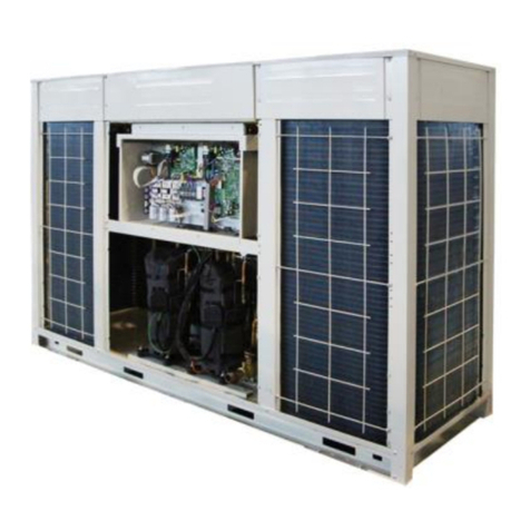
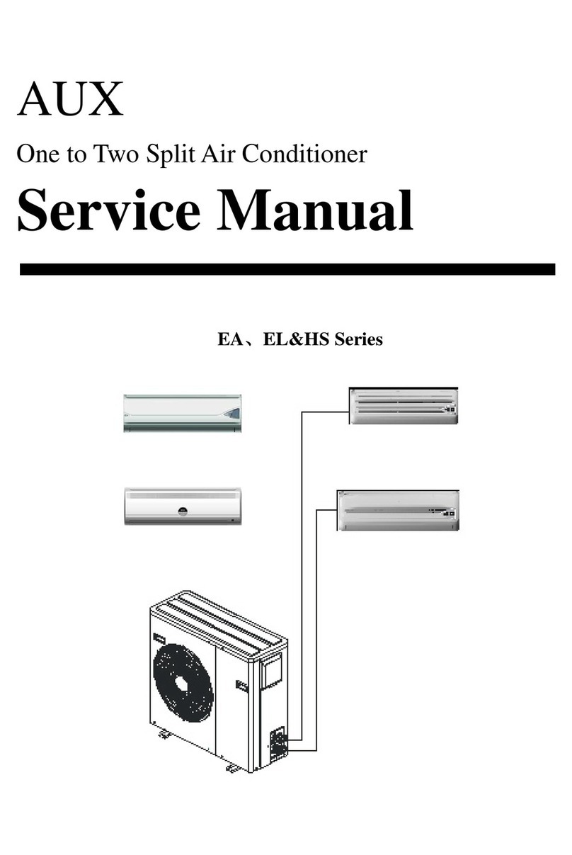
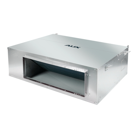
AUX ASW-H12B4/E Series User manual

Service Manual
Contents
1.Important Notice.............................................1
2.Technical Specification................................2-9
3.Operation Details.....................................10-13
4.Wiring Diagram.......................................14-15
5.Troubleshooting Guide.............................16-23
6.Explosion View And Parts List..................24-31
7.Refrigeration Cycle Diagram........................32
8. Control Functions Exposition..................33-42
Split type Wall Mounted Air Conditioner
E series

This service manual is intended for use by individuals possessing adequate
backgrounds of electrical, electronic and mechanical experience. Any
attempt to repair the appliance may result in personal injury and property
damage. The manufacturer or seller cannot be responsible for the
interpretation of this information, nor can it assume any liability in
connection with its use.
The information, specifications and parameter are subject to change due
to technical modification or improvement without any prior notice. The
accurate specifications are presented on the nameplate label.
How to order spare parts
To have your order filled promptly and correctly, please furnish the
following information:
1. Model No. with Indoor or Outdoor
2. No. in the Explosion View
3. Part Name
4. The quantity you ordered
IMPORTANT NOTICE
1

2-1 Appearance
2.Technical Specification
2

OUTDOOR UNIT
INDOOR UNIT
2-1 Appearance(continue)
2.Technical Specification
3

2-2 Nomenclature
1 AUX
2 Split-type
3 Wall mounted
4 Heat pump(only for heat pump)
5 Rated cooling capacity
6 The lever code of same cooling capacity
7Power supply
1 for 220V~/50Hz
2 for 208V-230V~/60Hz
3 for 110V~/50Hz
4 for 220V-240V~/50Hz
5 for 380V-415V-3~/50Hz
6 for 380V-3~/60Hz
7 for 208V-230V~/50Hz
8 Type(Formore detailsrefer to 1-1)
9 Refrigerant
Default for R22
R for R407c
R1 for R410a
4
2.Technical Specification

2-3 Product Technical Specification Diagram
Item
Model
Type
Performance
Cooling
Dehumidifying
Heating
Air Flow
Volume
Noise
Power supply
Rated
input
Rated
current
Input
factor
Starting current
Power
supply
cord
Length
Type
Fuse capacity
dimen-
sion D*W*H
Net weight
Connection
pipe
Liquid
Gas
Drain pipe
Compressor
Type
MotorMotor
Type
Rated input
Rated input
Fan motor
Type
Type
Heat exchanger(row*line
Refrigerant controller
Freezed oil capacity
Refrigerant/Charge(g)
Protection equipment
Cooling test condition
Max.Cooling test condition
Heat ing testcondition
Max.Heat ing testcondition
Input
Dimension
Indoor Indoor Indoor Indoor
Outdoor Outdoor Outdoor Outdoor
Wall mounted Wall mounted Wall mounted Wall mounted
Rotary
Plastic-sealed Iron-shell
Capillary
Inner
Indoor unit Outdoor unit
5
Cooling
Cooling
Cooling
Cooling
Cooling
Heating
Heating
Heating
Heating
Heating
Inner Inner Inner
Capillary Capillary Capillary
Rotary Rotary Rotary
Plastic-sealed Plastic-sealed Plastic-sealed
Through-flow
fan leaves
Through-flow
fan leaves
Axial-flow
fan leaves
Axial-flow
fan leaves
Through-flow
fan leaves
Through-flow
fan leaves
Axial-flow
fan leaves
Axial-flow
fan leaves
Iron-shell Iron-shell Iron-shell
2.Technical Specification

2-3 Product Technical Specification Diagram
2.Technical Specification
Item
Model
Type
Performance
Cooling
Dehumidifying
Heating
Air Flow
Volume
Noise
Power supply
Rated
input
Rated
current
Input
factor
Starting current
Power
supply
cord
Length
Type
Fuse capacity
dimen-
sion D*W*H
Net weight
Connection
pipe
Liquid
Gas
Drain pipe
Compressor
Type
MotorMotor
Type
Rated input
Rated input
Fan motor
Type
Type
Heat exchanger(row*line
Refrigerant controller
Freezed oil capacity
Refrigerant/Charge(g)
Protection equipment
Cooling test condition
Max.Cooling test condition
Heat ing testcondition
Max.Heat ing testcondition
Input
Dimension
Indoor Indoor
Outdoor Outdoor
Wall mounted Wall mounted
Rotary
Plastic-sealed Iron-shell
Capillary
Inner
Indoor unit Outdoor unit
Cooling
Cooling
Cooling
Cooling
Cooling
Heating
Heating
Heating
Heating
Heating
Inner
Capillary
Rotary
Plastic-sealed
Through-flow
fan leaves
Through-flow
fan leaves
Axial-flow
fan leaves
Axial-flow
fan leaves
Iron-shell
6

7
2-3 Product Technical Specification Diagram(continue)
Type
Performance
Cooling
Dehumidifying
Heating
Air Flow
Volume
Noise
Power supply
Rated
input
Rated
current
Input
factor
Starting current
Power
supply
cord
Length
Type
Fuse capacity
dimen-
sion D*W*H
Net weight
Connection
pipe
Liquid
Gas
Drain pipe
Compressor
Type
MotorMotor
Type
Rated input
Rated input
Fan motor
Type
Type
Heat exchanger(row*line
Refrigerant controller
Freezed oil capacity
Refrigerant/Charge(g)
Protection equipment
Cooling test condition
Max.Cooling test condition
Heat ing testcondition
Max.Heat ing testcondition
Input
Dimension
Indoor Indoor Indoor Indoor
Outdoor Outdoor Outdoor Outdoor
Wall mounted Wall mounted Wall mounted Wall mounted
Rotary
Plastic-sealed Iron-shell
Capillary
Indoor unit Outdoor unit
Cooling
Cooling
Cooling
Cooling
Cooling
Heating
Heating
Heating
Heating
Heating
Capillary Capillary Capillary
Rotary Rotary Rotary
Plastic-sealed Plastic-sealed Plastic-sealed
Through-flow
fan leaves
Through-flow
fan leaves
Axial-flow
fan leaves
Axial-flow
fan leaves
Through-flow
fan leaves
Through-flow
fan leaves
Axial-flow
fan leaves
Axial-flow
fan leaves
Iron-shell Iron-shell Iron-shell
Inner Inner Inner Inner
2.Technical Specification
Item
Model

2-3 Product Technical Specification Diagram
2.Technical Specification
Item
Model
Type
Performance
Cooling
Dehumidifying
Heating
Air Flow
Volume
Noise
Power supply
Rated
input
Rated
current
Input
factor
Starting current
Power
supply
cord
Length
Type
Fuse capacity
dimen-
sion D*W*H
Net weight
Connection
pipe
Liquid
Gas
Drain pipe
Compressor
Type
MotorMotor
Type
Rated input
Rated input
Fan motor
Type
Type
Heat exchanger(row*line
Refrigerant controller
Freezed oil capacity
Refrigerant/Charge(g)
Protection equipment
Cooling test condition
Max.Cooling test condition
Heat ing testcondition
Max.Heat ing testcondition
Input
Dimension
Indoor Indoor
Outdoor Outdoor
Wall mounted Wall mounted
Rotary
Plastic-sealed Iron-shell
Capillary
Inner
Indoor unit Outdoor unit
Cooling
Cooling
Cooling
Cooling
Cooling
Heating
Heating
Heating
Heating
Heating
Inner
Capillary
Rotary
Plastic-sealed
Through-flow
fan leaves
Through-flow
fan leaves
Axial-flow
fan leaves
Axial-flow
fan leaves
Iron-shell
8

9
2-3 Product Technical Specification Diagram(continue)
Type
Performance
Cooling
Dehumidifying
Heating
Air Flow
Volume
Noise
Power supply
Rated
input
Rated
current
Input
factor
Starting current
Power
supply
cord
Length
Type
Fuse capacity
dimen-
sion D*W*H
Net weight
Connection
pipe
Liquid
Gas
Drain pipe
Compressor
Type
MotorMotor
Type
Rated input
Rated input
Fan motor
Type
Type
Heat exchanger(row*line
Refrigerant controller
Freezed oil capacity
Refrigerant/Charge(g)
Protection equipment
Cooling test condition
Max.Cooling test condition
Heat ing testcondition
Max.Heat ing testcondition
Input
Dimension
Indoor Indoor Indoor Indoor
Outdoor Outdoor Outdoor Outdoor
Wall mounted Wall mounted Wall mounted Wall mounted
Rotary
Plastic-sealed Iron-shell
Capillary
Indoor unit Outdoor unit
Cooling
Cooling
Cooling
Cooling
Cooling
Heating
Heating
Heating
Heating
Heating
Capillary Capillary Capillary
Rotary Rotary Rotary
Plastic-sealed Plastic-sealed Plastic-sealed
Through-flow
fan leaves
Through-flow
fan leaves
Axial-flow
fan leaves
Axial-flow
fan leaves
Through-flow
fan leaves
Through-flow
fan leaves
Axial-flow
fan leaves
Axial-flow
fan leaves
Iron-shell Iron-shell Iron-shell
Inner Inner Inner Inner
2.Technical Specification
Item
Model

3. Operation Details
3-1 Remote Controller
10
+ button
This button canset room temperature.
Press it once,the temperature increases1 .Press it continu-
ously, the temperature increasesat the speedof 4 /s.
This function isinvalid when theappliance at theFan and
Auto mode.
Press the button, the horizontal airflowdirection plate can
adjust automatically. When you have the desired wind
direction, please pressit again, theairflow direction plate
will stop atthe situation.
SWING button
FAN button
Remark: The floor standing typeselect fan speedonly from
Low to High .
- button
MODE button
This button canset room temperature.
Press it once,the temperature decreases1 .Press it continu-
ously, the temperature decreasesat the speedof 4 /s.
This function isinvalid when theappliance at theFan and
Auto mode.
Button
High
Low Auto
Med
The closing state of remote controller:
Auto
Humidity display
Temperature display
Sleep display
Timer/Clock display
Fan speed display
Power display
Quiet display
Cool Dry Heat Wet Emission display
Mode display
Anion function display
Feeling display
Up/Down wind display
Left/Right wind display
Timer On/Off display

HEALTH
SLEEP
HUMIDITY FEELING/LOUVER
POWER
/QUIET
TIMER/CLOCK
The opening state of remote controller:
+ button
This button notonly can adjustclock time andthe timer time
but also canset room humidity.
Adjusting clock timeand timer time
Press it once,the time increasesone minute. Pressit for 1to
3 seconds, timedisplay will increaseat the speedof 2min/s.
For 3 to5 seconds, itwill increase atthe speed of10min/s.
For more than5 seconds, it will increase atthe speed of10min/s.
Setting room temperature and room humidity
Press it once,the humidity increases5%.
HEALTH button
Press this button,the LCD showsthe symbol, theanion
emission function ofthe air conditioneris started.
Press the buttononce again, The symbol disappears,the
function is cancelledat the sametime.
SLEEP button
Press this button,the LCD showsthe symbol, thesleeping
function of theair conditioner isstarted. After7 hours ofsetting
this function ,theair conditioner willbeoff automatically.
POWER button or POWER/QUIET button
POWER QUIT
QUIET
HUMIDITY button
Only under themode of Heatand Fan, Pressthis button once,
the LCD showsthe symbol, thewetting function ofthe air
conditioner is started.The initial humidity is 60%.Press the
+ or - button once ,thehumidity increases ordecreases
5%. The setting range is30%~60%.
Press the buttononce again, The symbol disappears, the
function is cancelledat the sametime.
Press the buttononce again, The symbol disappears, the
function is cancelledat the sametime.
This function isinvalid when theappliance under theFan mode.
This function isonly suitable forfrequency variable appliance.
When it displays POWER button:
When it displays POWER/QUIET button :
Press this button,the fan speedreach the highest, press itagain
it resume theforegoing fan speed.
3. Operation Details
3-1 Remote Controller(continue)
11

3. Operation Details
3-2 Operation Method
Press the button once more, The symbol disappears,
the function is cancelled at the same time.
Adjusting the clock time
/
off
on
Press this button in 5 seconds Under the state of no timer setting ,
the LCD flickers the symbol. Press the + or -
button to set the timer time. After finishing it, press this button
again in 10 seconds to affirm. If not, this operation is invalid.
- button
Adjusting clock time and timer time
Press it once ,the time decreases one minute. Press it for 1 to
3 seconds, time display will decrease at the speed of 2min/s.
For 3 to 5 seconds, it will decrease at the speed of 10min/s.
For more than 5 seconds, it will decrease at the speed of 10min/s.
Setting room temperature and room humidity
Press it once ,the humidity decreases 5%.
button
Press this button can be used to set the feeling function.
The LCD shows the actual room temperature when the function
set and it shows the setting temperature when the function cancelled.
This function is invalid when the appliance at the Fan mode.
FEELING button or LOUVER button
When it displays FEELING button:
When it displays LOUVER button:
Press this button, the vertical wind direction vanes can rotate automa-
tically, when you have the desired horizontal wind direction, press it
again, the vertical wind direction vanes will be stopped at the situation
of your choice.
TIMER/CLOCK button
Setting the ON/OFF timer time
When remote controller is at the on/off state, Press this button ,
the LCD flickers the symbol. Press the + or -
button to set the timer time. After finishing it, press this button
again in 10 seconds to affirm. If the setting time is the same as
the current time, this setting is invalid.
/
off
on
This button not only can adjust clock time and the timer time
but also can set room humidity.
1
12

3. Operation Details
3-2 Operation Method(continue)
3.Press the + or - button, you can set the temperature
range from 16 to 32 .
4.Press the FAN button, you can select fan speed from
Low , Med , High , Auto .
1.
2.
2.Press the + or - button, you can set the temperature
range from 16 to 32 .
3.Press the FAN button, you can select fan speed from
Low , Med , High , Auto .
2.Press the FAN button, you can select fan speed from
Low , Med , High .
1
13

4. Wiring Diagram
4-1 ASW- H 24B4/E*Indoor Unit
14

15
4-2 ASW- H 18B4/E* Indoor Unit
4. Wiring Diagram
Blue
Blue
Red
Black
To Indoor Unit
Compressor
Capacitor
Yellow
Red
Red
Brown
Green Blue
Green
Yellow
Yellow
Y/G
Fan Motor
Compressor
Capacitor
Fan Motor
Protector
Overcurrent
Red
White
Black
Black Black
Orientation
Brown
Valve
Red
Yellow
To Indoor Unit
Compressor
Capacitor
Red
Green
Red Black
Green
Yellow
Yellow
Y/G
Overcurrent
Protector
Fan Motor
Compressor
Black
Black
White
Red Brown
Fan Motor
Capacitor
Black

5-1The Foremost Inspecting Items
16
5.Troubleshooting Guide
1.The input voltage must be within +10% tolerance of the rated Voltage.
If it is not the case, the air-conditioner will probably not work normally.
2.Check the connecting cord between indoor unit and outdoor unit to see if it is properly
connected. The connecting must be done according to the wiring diagram, please also
notice that even different models may have the connecting cord of the same specification.
Please check if the marks at the connecting terminal and the marks on the cord can match,
otherwise, the air-conditioner will not work normally.
3.If the following phenomena are found, the problem is not from the air-conditioner itself.
Problems Causes
The motor is heard operating but
the air-conditioner dose not work
when the indoor unit is powered on
The compressor stops running but
the indoor fan motor keeps working
when it is atcooling mode with the
indoor temperature higher than set
temperature.
The compressor works discontinuously
at dehumidifying mode.
Since the air-conditioner is powered on, it will
come to working condition as long asyou press
the ON/OFF button of the remote control and the
signal is well received.
If you turn off the air-conditioner and restart it
immediately, it will return to normal in 3 minutes,
after that, the air-conditioner will automatically
adjust the indoor fan speed to what you set.
The air-conditioner will automatically control
the working of the compressor according to
the inside temperature
The air-conditioner dose not work
while the LED display is on.
The TIMER is set with the air-conditioner,it will
be in hold on condition. If the TIMER setting is
cancelled, the air-conditioner will return to
normal working condition.
The compressor stops internally or the fan motor
slows down to prevent the indoor heat exchanger
from being frozen.
The compressor works discontinuously
at cooling and dehumidifying mode,
and the indoor fan motor slows down.

5
1.Items
1 Check if the input voltageis correct?
2 Check if the AC power supply connecting is correct?
3 Check if the output voltageof the manostat L7805(IC2)is correct?
2.Trouble shooting procedure
Pull out thepower plug andreplug
it after some5 seconds
Does the buzzer ring?
Is the LEDlighten?
Has the signalbeen sent
Does the air-conditionerstart operating
after pressing the ON/OFFbutton of the
remote control?
normal
5-2 No Power Display
17
5.Troubleshooting Guide
Refer to thetrouble-shooting
of the remotecontrol
Check the connection
between power supplycord
and the connectingterminal,
then check thefuse
Is the primaryvoltage on
Cn2 normal?
Is the transformerOK?
Is the DCvoltage on the
PCB board OK?
Replace the
PCB board
Are the voltageof micro-controller
#8(compressor),#2(4-way valve) and
#6(outdoor fan motor)normal?
Is the voltage(5VDC)of the #15
(indoor fan motor)normal?
Is the portvoltage(0VDC) of the#3
normal?
Is the portvoltage(5VDC) of the#7
normal?
Is the portvoltage of the#27
normal?
Are the portvoltage of the#4and #5
normal?
Replace the
micro-controller
Replace the buzzer
Does it runnormally?
Are the voltage(IC4)of RY1(compressor),
RY3(indoor fanmotor)and (outdoor fan
motor) normal?
Check the connectionof
the compressor, indoorfan
motor and outdoorfan motor
Replace the Ry1,
RY3,and IC4
Is the outputvoltage of theIC2 normal?
Check PCB board
Replace the main
PCB board
Replace IC2

Refer to the procedure of proceeding
page
AC
134V-160V
The motor
running
status
#2 and #3
PCB Cn8
Replace the indoor
fan motor
5-3 The Indoor Fan Motor Does Not Work
18
5.Troubleshooting Guide
1.Items
1 Check if the indoor fanmotor is connected correctly tothe connector(CN8)?
2 Check if the AC input voltage is correct?
3 Check if the IC of indoor fan motor is connected correctly to the connector(CN2)?
4 Check if the capacity ofindoor fan motoris connected correctlyto the connector(CN8)?
2.Trouble shooting procedure
Pull out the power plug and replug
it after some 5 seconds
Is the LED lighten?
Is the controller output normal?
Is the fan motor voltage satisfied?
The probe position Normal
voltage
Replace FAC
Fan motor capacitor fails
PCB fails Replace PCB
Fan motor fails
The capacity of the fan
motor does not connect CN8
The micro-controller chip fails

19
5.Troubleshooting Guide
5-4 The Outdoor Unit Does Not Work
1.Items
1)
Check if the wire connectionof the outdoor connecting terminalis correct?
Check if the input voltageis correct?
2)
2.Trouble shooting procedure
Pull out the power plug and replug
it after some 5 seconds
Is the indoor controller normal? Check refer to the 5-2 part
The relay fails
Replace the relay
The outdoor unit
is abnormal
Is the output voltage of relay normal?
Is the connection on the terminal
correct ?
wire
This manual suits for next models
5
Table of contents
Other AUX Air Conditioner manuals

AUX
AUX ALMD-NHB Series Installation instructions

AUX
AUX Q Series User manual

AUX
AUX ARV Series Operating manual

AUX
AUX L Series User manual

AUX
AUX ARV Series User manual

AUX
AUX ASW-H09A4/SAR1DI User manual
AUX
AUX ASW-H09A4/EAR1-dw User manual
AUX
AUX ALCA-HA Series Installation instructions

AUX
AUX EA Series User manual

AUX
AUX ASW-H07B4/HSAR User manual
Popular Air Conditioner manuals by other brands

Retro Aire
Retro Aire R40C Installation, operation & maintenance manual

Frigidaire
Frigidaire FFRE103WA1 use & care

Mitsubishi Heavy Industries
Mitsubishi Heavy Industries DXK05ZTLA-WF user manual

York
York F2FP040H06 User's information manual

NEC
NEC RIH-6867 user manual

Panasonic
Panasonic CS-E9CKP operating instructions