RHINO RA96 User manual

OPERATION INSTRUCTIONS FOR
ROLLING CODE ALARM: RA96
INSURANCE APPROVED SPLIT SYSTEM MODEL WITH
ENGINE IMMOBILISATION AND BOOT RELEASE
MADE IN AUSTRALIA
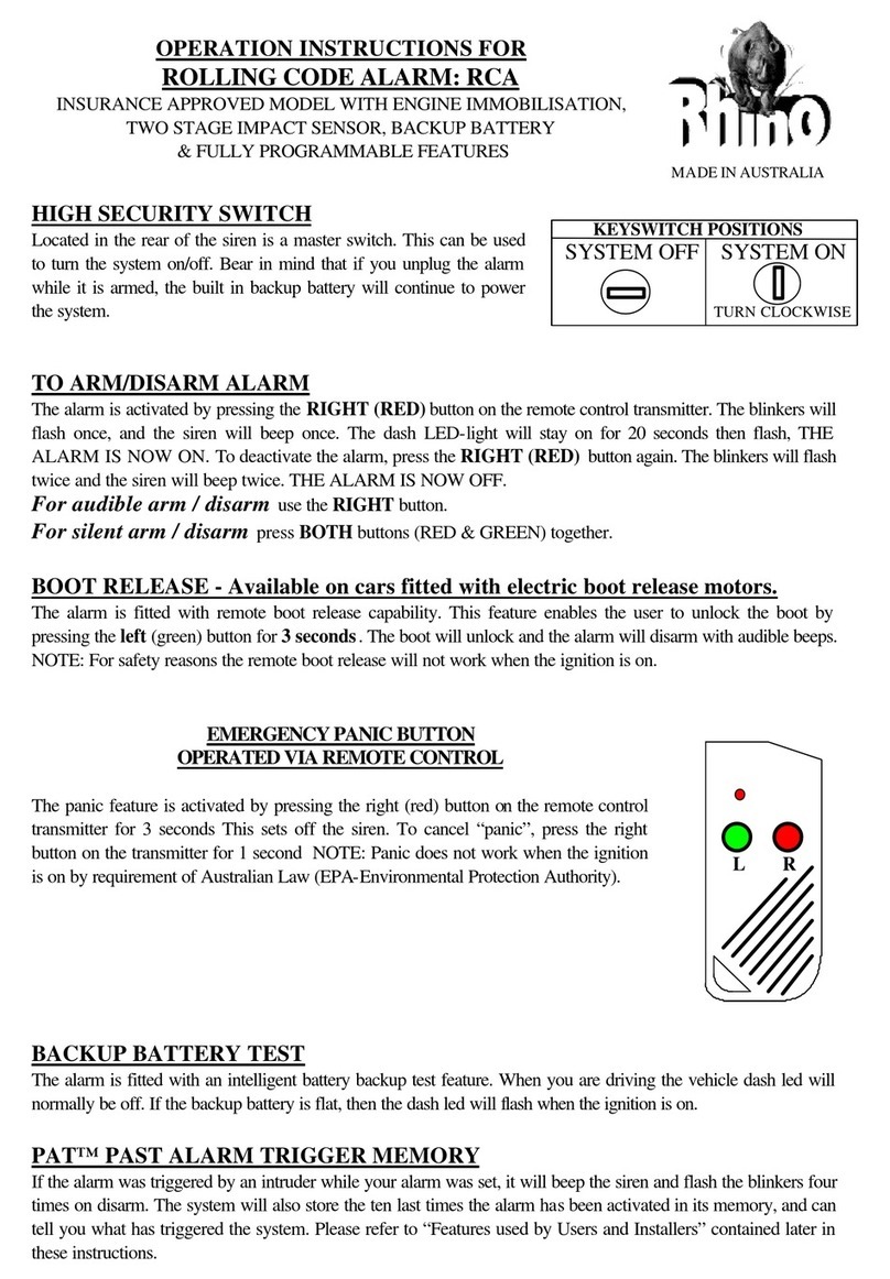
EMERGENCY PANIC BUTTON OPERATED VIA REMOTE
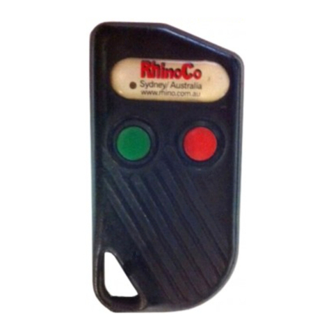
The panic feature is activated by pressing the right button on the remote control
transmitter for 3 seconds. This sets off the siren. To cancel “panic”, press the
right button on the transmitter for 1 second. NOTE: Panic does not work when
the ignition is on by requirement of Australian Law (EPA).
LR
TO ARM/DISARM ALARM
The alarm is activated by pressing the RIGHT button on the remote control transmitter. The
blinkers will flash once, and the siren will beep once. The dash LED-light will stay on for 20
seconds then flash, THE ALARM IS NOW ON. To deactivate the alarm, press the RIGHT
button again. The blinkers will flash twice and the siren will beep twice. THE ALARM IS NOW
OFF.
For audible arm / disarm use the RIGHT button.
For silent arm / disarm hold BOTHbuttons down for approximately 4 seconds.
PAT™ PAST ALARM TRIGGER MEMORY
If the alarm was triggered by an intruder while your alarm was set, it will beep the siren and
flash the blinkers four times on disarm. The system will also store the ten last times the alarm
has been activated in its memory, and can tell you what has triggered the system. Please refer
to “Features used by Installers/Servicemen” contained later in this instruction.
DOME LIGHT EXTENSION
The interior light will be automatically illuminated for 20 seconds when the driver disarms the
alarm. This allows the owner to verify that the vehicle is safe to enter plus giving the added
convenience of being able to see inside the vehicle even when the doors are closed. The interior
light will automatically turn off if the ignition is turned on, or if the alarm is armed again. This
feature is automatically disabled when passive arm and auto rearm are enabled.
DOOR AJAR WARNING FEATURE
If the vehicles doors are not properly closed when you try to activate your alarm system, the
blinkers will flash and the siren will continuously beep for 3 seconds to alert you that the
vehicle is not secure.

SELECTABLE PASSIVE ARM & RE-ARM FEATURE
These two fetures as outlined below can be turned on only if desired by the owner. When the
alarm initially has power connected to it, or when the system is turned off by the master switch
on the back of the siren, these features will be turned off.
PASSIVE ARMING: The alarm can automatically arm itself one minute after you leave your
vehicle provided that the ignition is turned off, and that at least one door has been opened and
closed ie. the owner has parked and has exited the vehicle. This feature will not lock the
vehicle where central locking is connected.
AUTOMATIC RE-ARM FEATURE: This feature prevents accidental disarming by the owner
ie. the owner turns the alarm off but is then distracted and forgets that they have deactivated
the system. If a door is not opened within one minute from when the system is turned off by
the remote, the system will re-arm and if central locking is connected it will re-lock the vehicle.
These features can either be both activated or both deactivated. To turn the features on/off
follow this procedure:
A) Turn the ignition on. N.B. The bonnet must be closed.
B) Immediately press the rightbutton on the remote control once only.
C) Immediately turn the ignition off.
D)1. If you turned the features on, the dash LED will flash once and the siren will beep
once after the ignition is turned off.
2. If you turned the features off, the dash LED will flash twice and the siren will
beep twice after the ignition is turned off.
BOOT RELEASE -Available on cars fitted with electric boot release motors.
The alarm is fitted with remote boot release capability. This feature enables the user to unlock
the boot by pressing the left button for 3 seconds. The boot will unlock and the alarm will
disarm without audible beeps. NOTE: For safety reasons the remote boot release will not work
when the ignition is on.
REMOVING OR ADDING ALARM SENSORS VIA THE REMOTE
CONTROL
~ To turn the Auxiliary and Shock sensor on or off, follow the procedures below;
A. Turn the ignition on.
B. Immediately press the Left button on the remote control once only.
C. Immediately turn the ignition off.
D. 1. If you turned the Auxiliary (Ultrasonic or Microwave Detector) and Shock Body Impact
Sensor on, the dash LED will flash once and beep once
after the ignition is turned off.
2. If you turned the Auxiliary (Ultrasonic or Microwave Detector) and Shock Body Impact
Sensor off, the dash LED will flash twice and beep twice after the ignition is turned off.
PRE-ALERT IMPACT WARNING WITH ETS™
This special feature provides a two stage impact sensing system. It gives the security conscious
owner a very sensitive impact sensor that will give a potential thief prior warning that the
vehicle is protected by this most formiddable alarm system. On detection the siren will simply
beep for a few seconds to warn away the thief. If the vehicle is attacked any further the system

will move into full siren mode. The unique ETS™ Environment Tuned Sensor is able to
distinguish between environmental shocks caused by aircraft, trucks, or extreme weather
conditions, and the the impact caused by any thief attempting to break in or other heavy
impacts. This process allows a trouble free sensitivity that ordinary alarms simply can not
provide.
LEARNING NEW TRANSMITTERS
To add a new transmitter to your alarm, simply follow the procedure below:
A. Turn the vehicles ignition on.
B. Immediately press and hold the right button on the original remote control until the siren
starts to beep (approximately 4 seconds) and then release the button.
C. Immediately press and hold the right button on the new remote control for at least 4 seconds.
D. Turn the vehicles ignition off.
E. The new remote control is now programmed into the alarm.
.
RHINO ALARM MODEL: RA96
SYSTEM FEATURES
~ All Microprocessor Controlled
~ Rolling Code Technology (Anti-Scanning, Anti-Code Grabbing)
~ Two SSR™ Solid State Remote Controls with Two Function Operation
~ Long Life Lithium Cell Remote Control Batteries
~ Ultra-Bright Red Flashing LED Light
~ Intelligent Pre-Alert Impact (Shock) Sensor with ETS™
~ Personal Panic Button via Remote Control
~ Automatic Siren Reset Period (30 Seconds)
~ Arming and Disarming Confirmation Beep
~ Visual Arming and Disarming via Blinkers
~ Selectable Current Sensing Circuit
~ All Points of Entry Protection
~ Passive Arming Programmable via Remote Control
~ Dome Light Extenension
~ Door Ajar Warning (If a Door is Left Open)
~ Automatic Re-arm in case of Accidental Disarm
~ Auto Re-lock for Accidental Disarm where Central Locking is connected
~ PAT™ Past Alarm Trigger Memory History Reporting Mode
~ Service and Override Mechanical Keyswitch
~ Safety Circuit Prevents Arming While Ignition On
~ Learning Mode for Optional Transmitters (Remote Controls)
~ Negative Pulse Central Locking Interface
~ Engine Immobilisation
~ Quiet Arming Selectable via Remote Control

~ Impact Sensor and Ultrasonic Isolation Programmable via Remote Control
~ Electric Boot Release Output via Remote Control
FEATURES USED BY INSTALLERS / SERVICEMEN
1. INSTALLER / SERVICE MODE:
Service mode is accessed by turning the keyswitch to the off position. This enables complete
deactivation of the system without using the remote control. This is normally done when other
mechanical/electrical work is performed on the vehicle. Installer mode is accessed by turning
the keyswitch to off then back to the on position. The installer test mode is used to quickly test
and fault find; it is used to check each sector input when door, hood, aux or voltage drop is
triggered. A signal is given via the blinkers, the dash LED light and the siren.
2. IMPACT SENSOR AND PRE-ALERT ADJUSTMENT: There are only two
positions of Impact (Shock) Sensor and Pre-Alert adjustment, and this is based on the position
mounting of unit. When the unit is fitted in a horizontal position, the impact sensor and pre-
alert are more sensitive. When fitted in a vertical position, they are less sensitive.
3. PAT™ PAST ALARM TRIGGER MEMORY READ OUT VIA SIREN
AND LED:
To access the PAT™ memory, turn the ignition to on with the bonnet opened i.e. bonnet switch
grounded. By pressing the remote control once, the alarm history is indicated via the siren and
LED. The memory is cleared whenever the power is removed from the alarm or if the
keyswitch is turned to off on the SB41 siren(service mode).
1 Beep, 1 Flash -Voltage Drop Alarm
2 Beep, 2 Flashes -Not Used On This Model
3 Beep, 3 Flashes -Shock Sensor Alarm
4 Beep, 4 Flashes -Power Fail Alarm
5 Beep, 5 Flashes -Ignition Alarm
6 Beep, 6 Flashes -Aux Alarm
7 Beep, 7 Flashes -Door Alarms
8 Beep, 8 Flashes -Bonnet / Boot Alarm
If two previous alarms were caused by i.e. voltage drop and shock sensor the LED will flash
and the siren will beep once for voltage drop, then no noise for 1 second then beep three times
for shock sensor. The memory will hold ten alarm memories. The last memory heard is the
most recent alarm sector triggered. To exit the memory mode, turn the ignition off and close
the bonnet.

IMPORTANT NOTE FOR INSTALLERS: Vehicles fitted with negative
or positive switching doors.
In order for the alarm system to function correctly, it is necessary for the doors to be
hard wired to the system. Please follow the wiring diagrams below:
NEGATIVE SWITCHING DOORS: POSITIVE SWITCHING DOORS: Use relay.
+12V Interior light
White wire ALARM 86
30 87a 87 White wire ALARM
Door Switch 85
Door Switch
+12V

WIRING INSTRUCTIONS
RED -
CONNECT TO CONSTANT +12 VOLTS VIA THE FUSE BOX AT THE POINT WHERE
THE INTERIOR LIGHT CIRCUIT IS POWERED. CURRENT (VOLTAGE) SENSING WILL
NOT WORK IF THIS PROCEDURE IS NOT FOLLOWED.
BLACK -
CONNECT TO A SUITABLE EARTH ON THE CAR BODY
ORANGE
(x2) -
CONNECT TO THE LEFT AND RIGHT INDICATOR CIRCUITS
OF THE VEHICLE TO FLASH THE INDICATORS
YELLOW -
CONNECT TO A +12 VOLTS IGNITION SWITCHED LEAD, WHICH DOES NOT FALL
TO 0 VOLT WHEN THE ENGINE IS CRANKED
DARK BLUE -
-
CONNECT TO PIN SWITCHES FOR BONNET
CONNECT TO PIN SWITCHES FOR BOOT (PLEASE NOTE: IT IS ADVISABLE TO WIRE
THE BOOT TO THE DOOR SWITCHES: THIS WILL PROVIDE “DOOR AJAR” WARNING
ON THE BOOT, AND ALSO SIGNAL THE AUTO RE-ARM FEATURE TO CANCEL IF THE
BOOT IS OPENED BY THE OWNER ON DISARMING THE SYSTEM.)
WHITE -
CONNECT TO EXISTING DOOR SWITCHES.
(PLEASE NOTE: ONLY NEGATIVE SWITCHING DOORS, IF POSITIVE DOOR
SWITCHING -MUST USE RELAYS TO REVERSE TO NEGATIVE -SEE DIAGRAM)
GREEN (X2)
Inside black cover -
LOCATE THE POSITIVE FEED WIRE TO THE STARTER, CUT THAT WIRE AND JOIN
THE TWO GREEN WIRES TO EITHER END OF THE STARTER FEED WIRE WHICH YOU
HAVE JUST CUT
GREEN (X2)
Outside black cover -
LOCATE THE POSITIVE FEED WIRE TO THE FUEL PUMP, CUT THAT WIRE AND JOIN
THE TWO GREEN WIRES TO EITHER END OF THE FUEL PUMP FEED WIRE WHICH
YOU HAVE JUST CUT
YELLOW/ BLACK -
THIS IS A SWITCHED NEGATIVE OUTPUT (-VE 150mA). CONNECT TO THE
NEGATIVE WIRE (USUALLY BLACK) ON ANY ACCESSORY USED i.e. ULTRASONIC /
GLASS BREAKAGE / MICROWAVE DETECTORS OR ETC
LIGHT BLUE -
THIS IS A NEGATIVE TRIGGER, AND SHOULD BE CONNECTED TO THE OUTPUT
CIRCUIT WIRE ON ANY ACCESSORY TO BE USED. (ie ULTRASONIC, MICROWAVE,
OR GLASS BREAK DETECTORS, ETC.)
BROWN
-
THIS IS THE NEGATIVE OUTPUT (150mA MAXIMUM) FOR THE BOOT RELEASE.
(Optional for use where electric boot release is to be connected)
VIOLET/BLACK -
NEGATIVE TRIGGER ON ALARM TO BE USED TO INTERFACE TO PAGER OR
OPTIONAL SIREN (100mA MAXIMUM)
ORANGE/BLACK -
NEGATIVE PULSE LOCK SIGNAL
PINK/YELLOW -
NEGATIVE PULSE UNLOCK SIGNAL
PINK -
CURRENT SENSING OVERRIDE. CONNECT TO POSITIVE POWER TO DISABLE
CURRENT SENSING
RED/WHITE -
NEGATIVE TRIGGER TO SIREN. CONNECT TO THE BROWN WIRE OF AN SB41.
VIOLET/YELLOW -
ALARM OVER RIDE. CONNECT TO THE WHITE WIRE ON AN SB41.
CURRENT SENSING
The alarm is fitted standard with current sensing. This feature incorporated in Rhino systems
has been proven to be very reliable. The alarm will detect any sudden drop in voltage in the
vehicle’s electrical system, for example if the interior light comes on, or if the electrical system
shows a voltage drop through tampering.
If removal of this feature is necessary, this can be achieved by connecting the pink wire coming
out from the loom tubing to the red power wire + 12V.

WARNING: If turbo cooling fans runafter the ignition key is turned off, you then must connect
the pink wire to the positive power feed wire of the electric cooling fan. This will override the
fan from causing false alarms due to voltage drop.
ALARM WIRING DIAGRAM
15A FUSE RED +12 VOLTS
BROWN BOOT RELEASE OUTPUT 5A FUSE ORANGE RIGHT INDICATORS
(Optional - 150mA maximum)
5A FUSE ORANGE LEFT INDICATORS
BLACK EARTH WIRE (GROUND)
YELLOW IGNITION INPUT
Connect to the vehicles body
GREEN CUT HERE STARTER
MOTOR
C GREEN
O PIN
N DARK BLUE BOOT / BONNET SWITCH
N
E ORANGE BLACK LOCK (NEG PULSE 150mA)
C
T PINK YELLOW UNLOCK (NEG PULSE 150mA)
O
R WHITE DOOR SWITCH (NEG. TYPES ONLY)
LIGHT BLUE AUX. INPUT (NEG. TRIGGER)
DASH LED VIOLET BLACK NEGATIVE OUT ON ALARM
PINK (100mA MAX)
GREY PINK CURRENT SENSE OVERRIDE
YELLOW BLACK NEG. OUT ON ARM 150mA
BROWN WIRE, NEG OUTPUT FROM ALARM
+12V
SB41 BATTERY BACKUP SIREN 15A FUSE
RED/WHITE
BROWN SIREN TRIGGER 87
86 87A 85
VIOLET/YELLOW
WHITE NEG WHEN OFF 30
BOOT MOTOR
YELLOW NOT USED (+ve trigger)
RED +12V POWER
BLACK EARTH (GROUND)
OPTIONAL BOOT RELEASE

IMPORTANTNOTE:Vehicles fitted with an interior light delay.
Vehicles fitted with an interior light delay require a diode to be added
to prevent the alarm giving a door ajar warning.
Please follow the wiring diagram below:
Interior light
DOOR DELAY
CIRCUIT
l
ll
l
l
ll
l
+12V
White wire Placeadiodehere
ALARM
DoorSwitches
FOR “NEGATIVE TRIGGER” ORIGINAL POWER LOCK SYSTEM
FOR “POSITIVE PULSE” POWERLOCK SYSTEM
CONNECT OPTIONAL RELAYS AS SHOWN
TO INSTALL NEW DOOR LOCK MOTORS
LOCK (ORANGE / BLACK FROM ALARM)
TO EXISTING DOOR
RELAYS
UNLOCK (PINK / YELLOW FROM ALARM)
LOCK (ORANGE/BLACK WIRE ON ALARM)
15A FUSE +12V
(PINK YELLOW) 87 87
UNLOCK 87a 87a
86 85 86 85
30 30
LOCK OUTPUT
UNLOCK OUTPUT

CONNECT OPTIONAL RELAYS AS SHOWN
LOCK (ORANGE/BLACK WIRE ON ALARM)
15A FUSE +12V
(PINK YELLOW) 87 87
UNLOCK 87a 87a
86 85 86 85
30 30
LOCK OUTPUT
UNLOCK OUTPUT
FOR POSITIVE AT REST THEN GOING NEGATIVE“OR” NEGATIVE AT
REST THEN GOING POSITIVE PUT 87’S TO +12V
CONNECT OPTIONAL RELAYS AS SHOWN
LOCK (ORANGE/BLACK WIRE ON ALARM)
+12V +12V OR GROUND
(PINK YELLOW) 87 87
UNLOCK 87a 87a
86 85 86 85
30 30
+12V
CAR CAR
EXISTING CUT CENTRAL
CENTRAL LOCKING
LOCKING INTERFACE
SWITCH
Table of contents
Other RHINO Security System manuals

RHINO
RHINO 232 User manual

RHINO
RHINO RA97 User manual

RHINO
RHINO 832 User manual

RHINO
RHINO RCA User manual

RHINO
RHINO PelcoD 2400bps on RS485 User manual

RHINO
RHINO Watchguard Digital V2 User manual

RHINO
RHINO RCA-2 User manual

RHINO
RHINO ADVANCED PANIC PACK User manual

RHINO
RHINO Watchguard Digital V2 User manual
Popular Security System manuals by other brands

Honeywell
Honeywell GKP-S8M Installation instructions and instructions for use

Europlex
Europlex 3806ZL operating instructions

Lorex
Lorex VANTAGE LH110 ECO SERIES instruction manual

Niko
Niko 05-203-01 user manual

Lorex
Lorex LHB926 Series Quick connection guide

DMP Electronics
DMP Electronics 1136 installation guide