AvaLAN AW5800i User manual

AW5800i
User’s Manual
Thank you for your purchase of the AW5800i Kit.
If you have any questions when configuring your
AvaLAN product
please send us an email:
Kit Contents:
(2) AW5800i Radio Units
(2) Power Adapters 6VDC/120VAC
(2) 5dBi Omni directional Antennae
Quick Setup for systems using the AW5800i radio:
1. Attach a 5800iHz antenna to each module.
2. Apply power to each AW5800i radio.
3. Connect an Ethernet cable from each AW5800i to a network device.
4. Send Ethernet traffic. For troubleshooting see page 2.
Each AW5800i radio automatically selects the best radio channel, encrypts the Ethernet
traffic and transports the data
wirelessly to its mate.
Any Ethernet device can be
connected to the AW5800i. The
AW5800i functions in place of an
Ethernet cable and provides a
transparent wireless point to point
Ethernet cable replacement. Cross-
over cables are not necessary as the
AW5800i automatically senses the
device (client or switch).
AW5800i
Ethernet
RJ45
Power
5.8GHz
Radio
Ethernet
Bridge
AW5800
i
Ethernet
RJ45
Power

LED display:
The AW5800i has a 16 LED display to display the status of the device.
Name Function Color
Power Unit has power and has successfully booted. Red
RF TX Radio transmission is occurring. Green
RF RX Radio reception is occurring. Green
Eth Link The Ethernet Port has a valid Ethernet connection Green
1 (channel)
2 (channel)
4 (channel)
8 (channel)
16 (channel)
32 (channel)
By adding the values that
are lit, the user can
determine the current
radio channel.
1 5728.125 Mhz
2 5730.208 Mhz
3 5732.292 Mhz
4 5734.375 Mhz
5 5736.458 Mhz
6 5738.542 Mhz
7 5740.625 Mhz
8 5742.708 Mhz
9 5744.792 Mhz
10 5746.875 Mhz
11 5748.958 Mhz
12 5751.042 Mhz
13 5753.125 Mhz
14 5755.208 Mhz
15 5757.292 Mhz
16 5759.375 Mhz
17 5761.458 Mhz
18 5763.542 Mhz
19 5765.625 Mhz
20 5767.708 Mhz
21 5769.792 Mhz
22 5771.875 Mhz
23 5773.958 Mhz
24 5776.042 Mhz
25 5778.125 Mhz
26 5780.208 Mhz
27 5782.292 Mhz
28 5784.375 Mhz
29 5786.458 Mhz
30 5788.542 Mhz
31 5790.625 Mhz
32 5792.708 Mhz
33 5794.792 Mhz
34 5796.875 Mhz
35 5798.958 Mhz
36 5801.042 Mhz
37 5803.125 Mhz
38 5805.208 Mhz
39 5807.292 Mhz
40 5809.375 Mhz
41 5811.458 Mhz
42 5813.542 Mhz
43 5815.625 Mhz
44 5817.708 Mhz
45 5819.792 Mhz
46 5821.875 Mhz
47 5823.958 Mhz
48 5826.042 Mhz
49 5828.125 Mhz
50 5830.208 Mhz
51 5832.292 Mhz
52 5834.375 Mhz
53 5836.458 Mhz
54 5838.542 Mhz
55 5840.625 Mhz
56 5842.708 Mhz
57 5844.792 Mhz
58 5846.875 Mhz
Green
Excellent link quality –
No retransmissions
Green
Very good link quality –
Few retransmissions
Green
Good link quality –
Occasional retransmissions
Amber
Fair link quality –
Some retransmissions
Amber
Poor link quality –
Many retransmissions
Red
Link Quality
Meter
The more LEDs that are
lit the higher the link
quality.
No link quality
No link available
Red
Troubleshooting:
See the online installation tutorial and FAQ at www.avalanwireless.com
No Power LED:
Check the power connections.
No Radio Link LED:
The radio is looking for its matched partner. If both units are powered up and the Power LEDs
are active they may be too far away to create the radio connection. Try other locations that
may have a less obstructed path or try to reorient the antennas.
Directional antennas get their best range when they are oriented to point directly at each
other with the antenna elements oriented in the same plane (eg. vertically or horizontally)
Radio LINK LED on but Link Quality Indicator is low:
The units may be too far away to create a good radio connection. Try other locations that
may have a less obstructed path or try to reorient the antennas.
No Ethernet LINK LED:
Check your network connections.
Installing Multiple systems in close proximity:
See the online installation tutorial and FAQ at www.avalanwireless.com
Still not working?
Temporarily use an Ethernet cable to see if the network is working over a wired connection.
If an Ethernet cable does not work then the problem is with the network.

Advanced Settings:
Automatic frequency selection mode (DIP switches – all OFF for automatic mode)
The AW5800i is designed to automatically select and continuously optimize the performance of its
radio channel. The radio channel is monitored to ensure it is providing low error rates necessary for
successful radio transmission. In the event that the error rate rises, the AW5800i will autonomously
change to a new channel. There are 58 non-overlapping channels.
Manual frequency selection mode
This mode enables the user to restrict the operation of the AW5800i to a specific channel. This can
be done by setting DIP switches 3-8 as shown in the table below.
DIP 3 DIP 4 DIP 5 DIP 6 DIP 7 DIP 8
Add 1 Add 2 Add 4 Add 8 Add 16 Add 32
0
1x5728.1250 Mhz
2 x 5730.2083 Mhz
3 x x 5732.2917 Mhz
4x5734.3750 Mhz
5 x x 5736.4583 Mhz
6 x x 5738.5417 Mhz
7 x x x 5740.6250 Mhz
8x5742.7083 Mhz
9 x x 5744.7917 Mhz
10 x x 5746.8750 Mhz
11 x x x 5748.9583 Mhz
12 x x 5751.0417 Mhz
13 x x x 5753.1250 Mhz
14 x x x 5755.2083 Mhz
15 x x x x 5757.2917 Mhz
16 x5759.3750 Mhz
17 x x 5761.4583 Mhz
18 x x 5763.5417 Mhz
19 x x x 5765.6250 Mhz
20 x x 5767.7083 Mhz
21 x x x 5769.7917 Mhz
22 x x x 5771.8750 Mhz
23 x x x x 5773.9583 Mhz
24 x x 5776.0417 Mhz
25 x x x 5778.1250 Mhz
26 x x x 5780.2083 Mhz
27 x x x x 5782.2917 Mhz
28 x x x 5784.3750 Mhz
29 x x x x 5786.4583 Mhz
30 xxxx 5788.5417 Mhz
31xxxxx 5790.6250 Mhz
32 x5792.7083 Mhz
33 x x 5794.7917 Mhz
34 x x 5796.8750 Mhz
35 x x x 5798.9583 Mhz
36 x x 5801.0417 Mhz
37 x x x 5803.1250 Mhz
38 x x x 5805.2083 Mhz
39 x x x x 5807.2917 Mhz
40 x x 5809.3750 Mhz
41 x x x 5811.4583 Mhz
42 x x x 5813.5417 Mhz
43 x x x x 5815.6250 Mhz
44 x x x 5817.7083 Mhz
45 x x x x 5819.7917 Mhz
46 x x x x 5821.8750 Mhz
47 x x x x x 5823.9583 Mhz
48 x x 5826.0417 Mhz
49 x x x 5828.1250 Mhz
50 x x x 5830.2083 Mhz
51 x x x x 5832.2917 Mhz
52 x x x 5834.3750 Mhz
53 x x x x 5836.4583 Mhz
54 x x x x 5838.5417 Mhz
55 x x x x x 5840.6250 Mhz
56 x x x 5842.7083 Mhz
57 x x x x 5844.7917 Mhz
58 x x x x 5846.8750 Mhz
AUTO MODE
Channel # Tx Frequency
Site survey mode (DIP switch 2 - default is OFF for normal operation)
In this mode the AW5800i can perform a site survey. With this mode activated the radios send and
receive at 100% capacity by transceiving self-generated simulated data. The installer can monitor the
Link Quality display to assess channel quality while optimizing antennae orientation. The installer
can manually select each channel to evaluate performance and identify the best channels for
operation. By identifying channels with poor performance it is possible to identify possible interferers
and use “manual frequency selection mode” to avoid portions of the band or select a fixed operating
frequency. Important note: Ethernet traffic does not get transported while the radios are in this
mode.

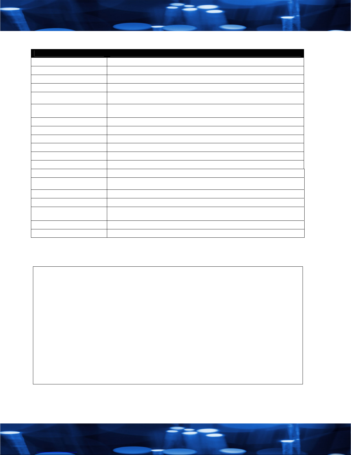
Technical Specifications: (typical)
Characteristic Specification - description
RF transmission rate: 1.54 Mb/s
Ethernet Throughput: 1.01 Mb/s
Output power: +20dBm (20 Watts EIRP used with 23dBi antennae AW23-5800)
Receive sensitivity: -98dBm at 10e-4 BER (-121dBm with 23dBi antennae AW23-5800)
Radio link budget: 128dB with included 5dBi antenna AW5-5800
164dB with 23dBi antennae AW23-5800
Line of Sight Range: 2 Miles Line of Sight with included 5dBi antenna AW5-5800
40 miles Line of Sight with 23dBi antennae AW23-5800
Radio channels/bandwidth: 58 Non-overlapping with 2.0833MHz spacing and 1.75MHz occupied bandwidth.
Automatic frequency select: Yes – radio channel automatically selected and adaptively optimized
Connector types: RF RPTNC Female / Ethernet RJ45 10BaseT / Power Jack P5-2.1mm ID
Status LEDs: Power, Ethernet Link, RF RX, RF TX, 6/Channel and 6/Link Quality
Error correction technique: Sub-block error detection and retransmission.
Adjacent-band rejection: SAW receiver filter attenuates cellular and pager interference.
Regulator type: Linear Regulator
Power consumption: Transmit – 2.0W at 5VDC
Receive – 1.0W
Voltage: 5-9VDC at P5 power jack (center positive)
Temperature range: -40°C to 70°C
Current draw: Transmit 400mA
Receive 200mA
Power over Ethernet 802.3af: Use with 5VDC splitter with P5 connector. Linksys WAPPOE recommended.
Radio Size: 150x80x35mm
Product limited warranty:
This product is warranted to the original purchaser for normal use for a period of 180 days from the date of purchase. If a
defect covered under this warranty occurs Avalan will repair or replace the defective part, at its option, at no cost. This
warranty does not cover defects resulting from misuse or modification of the product.
Compliance Statement ( Part 15.19 )
This device complies with Part 15 of the FCC Rules.
Operation is subject to the following two conditions:
1. This device may not cause harmful interference, and
2. This device must accept any interference received, including interference that may cause undesired operation.
Warning ( Part 15.21 )
Changes or modifications not expressly approved by the party responsible for compliance could void the user’s authority to operate the
equipment.
RF Exposure ( OET Bulletin 65 )
To comply with FCC RF exposure requirements for mobile transmitting devices, this transmitter should only be used or installed at locations
where there is at least 20cm separation distance between the antenna and all persons.
Information to the User - Part 15.105 (b)
Note: This equipment has been tested and found to comply with the limits for a Class B digital device, pursuant to part 15 of the FCC Rules.
These limits are designed to provide reasonable protection against harmful interference in a residential installation. This equipment generates,
uses and can radiate radio frequency energy and, if not installed and used in accordance with the instructions, may cause harmful interference
to radio communications. However, there is no guarantee that interference will not occur in a particular installation. If this equipment does
cause harmful interference to radio or television reception, which can be determined by turning the equipment off and on, the user is
encouraged to try to correct the interference by one or more of the following measures:
--Reorient or relocate the receiving antenna.
--Increase the separation between the equipment and receiver.
--Connect the equipment into an outlet on a circuit different from that to which the receiver is connected.
--Consult the dealer or an experienced radio/TV technician for help.
V5 August 21, 2006
Table of contents
Other AvaLAN Radio manuals

AvaLAN
AvaLAN AW900iTR User manual

AvaLAN
AvaLAN AW900XTR User manual

AvaLAN
AvaLAN AW5810HTA User manual

AvaLAN
AvaLAN AW900xTR-INTL User manual

AvaLAN
AvaLAN AW900T User manual

AvaLAN
AvaLAN AW900 TR Series User manual

AvaLAN
AvaLAN AW2400xTR User manual

AvaLAN
AvaLAN AW58103HTS Installation and operating instructions

AvaLAN
AvaLAN AW900iTR User manual

AvaLAN
AvaLAN AW900F User manual
Popular Radio manuals by other brands

Delta-T Devices
Delta-T Devices SunScan SS1-RL4 user manual

Groov-e
Groov-e GV-DR01 instruction manual

Silvercrest
Silvercrest KH 239 operating manual

Silvercrest
Silvercrest SDR 1 A1 Operation and safety notes

One Remote
One Remote DabWiFI7 user guide

Cambridge Sound Works
Cambridge Sound Works SoundWorks Radio 820HD user manual