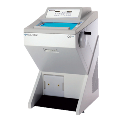
Avantik QS12 User manual

The Avantik QS12 and QS12UV Cryostats
Your laboratory...refined, efficient, easy.
36 Commerce Street, Springeld, NJ 07081 / USA
www.avantik-us.com
800-783-9424
INSTRUCTION MANUAL
CRYOSTAT
QS12
THE REVOLUTIONARY
388159 - English - 04-2017

Notes

Notes

Company Information
4
Important Note Regarding Instrument Variants
is document is designed for use with the .
Only two variants UVC and non UVC are available on this instrument and the instructions contained in this manual are
not specic to any one variant. us some features described may not be available on your instrument.

Company Information
5
Symbols
e following symbols and conventions may be used throughout this document and on the instrument:
is symbol is used on the instrument, or in a document, to indicate that instructions must be
followed for safe and correct operation. If this symbol appears on the instrument, always refer to
the operator guide.
is symbol is used on the instrument, or in a document, to indicate that there are potential
biological risks associated with the instrument and / or instrument use. Always use Good
Laboratory Practice.
is symbol indicates that a surface is hot. If this symbol appears on the instrument, always refer
to the operator guide.
Cold surface, if necessary, use gloves
is symbol is shown in the manual and on the instrument to indicate that hand injuries are
possible due to moving parts. Take suitable precautions.
Cutting hazard, sharp edges, watch your ngers.
is symbol is used on the instrument, or in a document, to indicate that irritants or potentially
harmful chemicals are present. Refer to the Material Safety Data Sheets for the products, and
always use Good Laboratory Practice.
is symbol is used to identify the UV disinfection system. Do not open the window when the
disinfection cycle is in process and do not look directly at the UV light.
Manufacturer.

Company Information
Table ofContents
Notes ..................................................................................................................................................................................2-3
Important Note Regarding Instrument Variants .................................................................................................................... 4
Symbols................................................................................................................................................................................. 5
Table of Contents.................................................................................................................................................................. 6
1 - Safety Information ........................................................................................................................................................... 9
General Safety................................................................................................................................................................... 9
Chemical Safety .............................................................................................................................................................. 10
Environment................................................................................................................................................................... 10
Warranty Statement........................................................................................................................................................ 10
2 - Introduction................................................................................................................................................................... 11
Intended Use .................................................................................................................................................................. 11
Instrument Features ........................................................................................................................................................ 11
Technical Specications .................................................................................................................................................. 12
Mechanical Specications ........................................................................................................................................... 12
Electrical Specications............................................................................................................................................... 12
Environmental Specications...................................................................................................................................... 12
3 - Instrument Setup ........................................................................................................................................................... 15
Unpacking and Repacking .............................................................................................................................................. 15
Unpacking Procedure ................................................................................................................................................. 15
Location & Setup............................................................................................................................................................ 18
Identication of Parts...................................................................................................................................................... 19
Solid Knife Holder.......................................................................................................................................................... 20
Disposable Blade Holder EC........................................................................................................................................... 21
Disposable Blade Holder EC 70...................................................................................................................................... 22
Inserting the blade: ..................................................................................................................................................... 22
Set Up ........................................................................................................................................................................ 24
Specimen Setup .......................................................................................................................................................... 25
4- Operation ....................................................................................................................................................................... 26
Switching On.................................................................................................................................................................. 26
System Interfacing........................................................................................................................................................... 27
Using the Touch screen .............................................................................................................................................. 27
Note........................................................................................................................................................................... 27
Main Screen ............................................................................................................................................................... 27
Setting Preferences .......................................................................................................................................................... 29
Quick Freezing of the Specimen ................................................................................................................................. 29
To set the Specimen Head Position: ........................................................................................................................... 30
Microtome/Chamber Temperature............................................................................................................................. 30

Chapter 1 --- Safety Information
7
Trim and Fine Sectionickness ............................................................................................... ................................ 31
Multi Function Bar..................................................................................................................................................... 32
Trim Button................................................................................................................... ............................................ 32
Trimming................................................................................................................................................................... 32
Time and Date ........................................................................................................................................................... 32
Outstanding Service Message...................................................................................................................................... 32
Handwheel Lock ................................................................................................................ ........................................ 34
Menu .......................................................................................................................... ............................................... 34
Language ...................................................................................................................... .............................................. 35
Time and Date ........................................................................................................................................................... 35
Set the Duration of the UV Cycle:.............................................................................................................................. 38
Chamber Light ........................................................................................................................................................... 39
Standbymode............................................................................................................................................................. 40
Display Lock .............................................................................................................................................................. 40
Defrost ....................................................................................................................................................................... 41
Immediate Defrosting................................................................................................................................................. 41
Programming the Daily Defrost Cycle ........................................................................................................................ 42
Log File ...................................................................................................................................................................... 43
Factory Settings .......................................................................................................................................................... 44
Screen........................................................................................................................ ................................................. 45
Service ....................................................................................................................... ................................................. 45
Heat Extractors............................................................................................................... ............................................ 45
Sectioning Procedures ..................................................................................................................................................... 46
Cutting Movement and Retraction ............................................................................................................................. 46
Trimming and First Cuts....................................................................................................... ..................................... 46
Sectioning and Taking O Sections............................................................................................................................ 47
Hand Wheel Lock ...................................................................................................................................................... 47
Mechanical Handwheel Brake..................................................................................................................................... 47
How to Avoid Malfunctions............................................................................................................................................ 48
5 - Troubleshooting........................................................................................................... .................................................. 49
Troubleshooting Tables .................................................................................................................................................. 49
Tips for Successful Sectioning ......................................................................................................................................... 51
Temperature list for cryo-sectioning............................................................................................................................ 51
6 --- Maintenance and Care of the QS12 .................................................................................................................... 53
Cleaning the Touch Screen Display ................................................................................................................................ 53
Shutting O for Cleaning ............................................................................................................................................... 53
Cleaning and Care .......................................................................................................................................................... 54
Cleaning and care during routine work:...................................................................................................................... 54

Chapter 1 --- Safety Information
8
Cleaning the cooling Vent .......................................................................................................................................... 54
Conditions for the transportation of the instrument........................................................................................................ 55
Returning the instrument for repair or routine Maintenance....................................................................................... 55
Accessories standard equipment....................................................................................................................................... 57
Index................................................................................................................................................................................... 58

Chapter 1 --- Safety Information
9
1- Safety Information
Avantik Biogroup instruments are designed for convenient and reliable service; however, improper use or handling by a user
may damage the instrument, or cause a hazard to health. e instrument must not be used in a manner not specied by
Avantik Biogroup. Correct maintenance procedures are essential for consistent performance.
Any problems and queries should be referred to your Avantik Biogroup service department.
e following sections contain important information for the safe setup and use of the instrument,
and should be read and understood by the user before using the instrument.
General Safety
is instrument, as supplied, conforms to IEC 61010-1 and IEC 61010-2-101; however, the
addition of chemicals introduces potential hazards. Good Laboratory Practice must be employed
and consideration must be given to the potential for hazard when dealing with these chemicals.
Do not use the instrument in close proximity to strong electromagnetic radiation, as these may
interfere with the proper operation. e electromagnetic environment should be evaluated prior to
operation of the device.
Good Laboratory Practice must be used when handling tissue samples to prevent cross
contamination and infection. e user should complete a risk assessment to determine any potential
hazards related to tissue handling.
•Do not remove any panels or access covers, unless specically instructed to do so. e
instrument does not have any user serviceable parts. Potentially lethal voltages are present
inside the instrument.
•e instrument must be properly connected to a good earth (ground) via the Mains
input supply and positioned such that it is possible to interrupt the Mains supply at the
source by removing the plug from thesocket.
•Use only factory approved accessories or replacement parts within the instrument.
•Only use reagents/supplies recommended in the operator guide.

noitamrofnIytefaS---1retpahC
10
Chemical Safety
ls creates potential hazards. Avantik Biogroup has adopted the following position with
regard to the subject of volatile chemicals used in laboratories:
•nstrument, do so at their own risk.
•All chemicals recommended by Avantik Biogroup have auto-ignition temperatures
considerably above any surface temperatures that can be reached during a single fault
failure on the instrument.
•on in any areas of the instrument where
chemicals are stored, or likely to leak into, in a single fault condition.
•of the contents of
properties of the chemicals they are using.
•out any legally required assessment of chemicals used and is using
Good Laboratory Practice.
Warranty Statement
Avantik is proud of our quality, reliability and of our after-sales service. We continuously strive to improve our
service to our customers.
Please ask your distributor or Avantik representative about service contracts which can help maintain your
instrument in an optimal operating condition.
found in the delivery documentation or from your dealer or representative.
Please note that your warranty may be invalidated if:
•
•Accessories and reagents which have not been approved by Avantik are used.
•ns.
.

Chapter 2 - Introduction
2- Introduction
Intended Use
e QS12 is an in vitro diagnostic high-performance cryostat designed to prepare tissue
sections of frozen samples in medical, pharmaceutical and research laboratories. Only trained
laboratory personnel may operate the QS12.
e instrument may only be operated within the scope of its intended use and as per the instructions given in this manual.
Any other use of this instrument is considered as improper operation.
Instrument Features
e QS12 is a precision-engineered, ergonomically-designed, high-performance cryostat in modular design with a
stainless steel cooling chamber. Some of its features are:
•Colour touch-screen user interface.
•Lighted window, easy positioning.
•Intricate freezing device down to max. -55°C via the cryobar.
•Automatic or manual defrost.
•Stainless Steel cooling chamber.
•Chamber temperature regulation variable from +5°C down to -35°C.

Chapter 2 - Introduction
12
Technical Specifications
MechanicalSpecifications
Depth 760 mm (29.9 in)
Width 640 mm (25.19 in) w/o handwheel
Height Range 1150 mm ( 45.3 in)
Maximum Weight 143 kg (315.2 lb)
ElectricalSpecifications
Power Requirements
Dedicated 20 Amp circuit recommended.
100V, 50/60Hz, 7A, +/-10%, 110-120V, 60Hz, 7A, +/-10%
220-240V, 50/60Hz, 4A, +/-10%
BTU 1020BTU/hour
Environmental Specifications
For Indoor Use Only
Temperature (Operating Limits) +5°C to +35°C (+41°F to +95°F)
(at a max. Relative humidity of 60%)
Temperature
(Recommended Operation)
+15°C to +30°C (+59°F to +86°F)
Note
Performance may deteriorate when operated outside of this range.
Temperature
(Transport and Storage) -20°C to+50°C (-4°F to 122°F)
Relative Humidity Max. 60% RH up to 35°C
Altitude Up to 2000 m (6,500 ft)
Pollution Degree 2
Over Voltage Category II
Floor Loading Requirements 230 kg/m² (507 lb/ft²)
Safety Class I
Sound Emission 45 dB (A) - measured with 1m distance to the instrument.
Refrigerant R404a, lling amount: 100...120V 175g 220...240V 175g

Chapter 2 - Introduction
13
Cooling Specifications
Cryobar Cooling (Peltier Element) Max. - 55°C (-67°F)
Chamber Temperature Max. -35°C -2K/+1K (-31°F -2K/+1K) at +20°C room Temp.
(decrease 0,7°C/1°C room temp. increase)
Defrosting Options Programmed / Immediate
Microtome and Sectioning Specifications
mµ005---1
mµ001---1
01---1 µm in 1 µm steps
10 µm --- 20 µm in 2 µm steps
20 µm --- 50 µm in 5 µm steps
50 µm --- 100 µm in 10 µm step
mµ005---5
03---5 µm in 5 µm steps
30 µm --- 100 µm in 10 µm steps
02nimµ002---mµ001 µm steps
05nimµ005---mµ002 µm steps
Specimen Retraction (Return Travel) 20 µm
Vertical Specimen Stroke 64 mm
Horizontal Specimen Movement 28 mm
Specimen Approach Automated via arrow buttons
Chuck Size 30, 40 mm (additional special sizes are available)
Specimen Orientation x - and y - axes universal 8° with zero positioning; z - axis up to 360°
Coarse Feed Motorized
Cutting Drive Manual via handwheel
Handwheel Lock Mechanical
Clearance Angle Adjustment Disposable blade carrier 8- 16°

Chapter 2 - Introduction
14
Factory settings
Counter Mode C=0
Retraction ON
Language English
Chamber Temperature -20°C
Fine 1 µm
Trim 5 µm
Chamber Light 100%
Screen Brightness 100%
Stepper Motor Initialization Yes
CryobarOFF
Defrost Cycle (Automatic) ON (00:00 Night)
Section Counter 0
Section Sum 0

---3retpahC Instrument Setup
3 - Instrument Setup
Unpacking and Repacking
Safety Precautions
Use safe lifting practices when moving the QS12. At least two people are required to safely move the
instrument.
QS12 has a high centre of gravity and care should be taken when moving.
Do not tip the QS12 more than 30° from the upright position.
After moving the QS12, wait at least 8 hours before switching on to allow the refrigerant to settle -
failure to do so may cause damage to the unit.
Note
e carefully stored for use in any future instrument shipment.
Unpacking Procedure
General Information:
•Inspect the packaging, if it is damaged and/or the contents do not match the supplied packing list, inform your
•Ensure that these Instructions are retained for future use.
•foam
spacers inside the container. A wooden cover protects the top of the instrument.
•In unpacking be aware of the weight (143 Kg/315.2 lbs) of the instrument, at least two people are required to
safetly move the instrument.
Unpacking the Instrument:
•Cut through the three packing straps and remove
the packing.
•Remove the upper wooden co
•e hinges of the upper wooden cover are secured
with tape.
•Remove this tape.
•
2).
•Remove the upper and lower supporting fo
1.3, 1.4, 1.5, 1.6) from the QS12.
Fig 1
Avantik representative.

Chapter 3 --- Instrument Setup
16
Note
e upper wooden cover now serves as a ramp (fig. 1a.1) on which the QS12 can be moved from the pallet to the oor
by using the handle (g. 1a) (item 2).
•e hinges of the upper wooden cover (g. 1)
(item 1) are inserted into the screws of the
bottom plate (g. 1a) (item 3). e correct
side for this is marked with arrows.
•e tool (g. 2a) (item 2) for the height
adjustment of the setting feet of the QS12 is
packed together with the accessories of the
QS12 (separate carton on the foot rest of the
QS12).
•Turn the setting feet completely upwards via
this tool so that the QS12 stands with its
rollers on the bottom plate (g 1a) (item
3).
•Via the handle (g 1a) (item 2), roll the QS12
from the bottom plate (g. 1a)(item 3) over
the wooden cover
(g. 1a) (item 1). In doing so, the rear side of
the instrument must face the incline (g. 1a) (
item1).
Fig 1a
e instrument is very heavy. While the instrument rolls down the ramp, it must be carefully controlled.
•Now the QS12 can be rolled to its site of installation.
•For possible return shipments, please keep all packing materials.
•In the future, if the instrument is transported by forklift, truck, train, ship or aircraft, it must be packed in the
original shipping container with all transportation locks in place.
When Unpacking the Instrument, be sure that:
•Enough ventilation for the cooling system is
guaranteed.
•e distance between the wall and rear panel is
approx. 15 cm/ 6”. For this, install the distance
bolts (g 2) (item 1).
•e suction vent areas on either side are kept
free (g. 2) (item 2).
•e mains switch for separating the instrument
from the power supply is accessible at any time.
Fig 2

---3retpahC Instrument Setup
17
The installation site must also be free from:
•Draught by open doors or by air conditioning
systems.
•Direct exposure to sunlight into the cooling
chamber.
Note
Both measures reduce the formation of frost and therefore
result in more favourable work conditions. High air
moisture as well as high ambient temperatures reduce the
maximum performance of the instrument.
•To stabilize the complete unit, tighten the sc
2a) (item 1) by using the attached tool.
•Install the separate, packed handwheel handle.
Fig 2a
•Install the separately packed handwheel handle
on the handwheel with the attached screw by
means of the Allan key.
Fig 2b
Repacking the Instrument
To repack the instrument, follow the above instructions in reverse order.

18
---3retpahC Instrument Setup
Location & Setup
When deciding where to locate the QS12, the following items must be taken into consideration:
•Approximately 10 cm (4 in) must be allowed around the cooling system to allo
•Approximately 15 cm (6 in) must be allowed between the wall and the rear panel.
•n the sides of the rear panel must be unobstructed at all times.
•cket must be accessible at all times.
•location must be free from draughts, open doors or air conditioning systems.
•
Note
peratures resulting in more
favourable working conditions. Locations which have high humidity and / or high ambient temperatures can reduce the
performance of the instrument.
moving during operation.

Chapter 3 --- Instrument Setup
19
Identification ofParts
Overview
1 Cryo chamber
2 Cryo chamber Window
3 Touch Screen
4 Connections Panel
5 Handwheel Mechanical Lock
6 Handwheel
7 Water Drain Reservoir
Connections Panel
8 USB port
9 Power Switch
10 Power Socket
Cryochamber
11 Cryobar and Cooled Storage Area
12 Specimen Head
13 Tool storage
14 Handwheel Mechanical Brake Button
15 Waste Tray

Chapter 3 --- Instrument Setup
20
Solid Knife Holder
Inserting the knife:
e knife is inserted into the slot behind the clamping plate.
1 Clamping Plates
2 Clamping Screws
3 Anti-roll Plate
4 Anti-roll Plate Turning Lever
5 Knurled Screw
6 Anti-roll Plate Knurling Screw
7 Knife Guards
8 Clearance Angle Clamping Lever
9 Clearance Angle Scale
Inserting the knife:
•
•
e knife is inserted into the knife carrier either from the side or from the front, independently if one or two
clamping plates have been removed.
Loosen the clamping screws.
•Turn the turning lever in a clockwise direction to tilt the anti-roll plate forwards.
Insert the knife.
•Turn the turning lever in a counter clockwise direction to put the anti-roll plate against the knife.
Note
Insert the glass anti-roll plate parallel towards the blade edge.
•en tighten the clamping screws to x the knife into position.
If the cutting area of the knife is no longer usable, the knife can be moved:
•Open the clamping screws and move the knife to the left or right side as required.
•Fix the knife again via the clamping screws.
To avoid the danger of injury on the knife during adjustment of specimen, always position the knife guards
over the blade edge.
Height adjustment of the knife:
•Loosen the clamping screws.
•Via the knurled screws which are placed on the left and right side of the knife carrier, adjust the height of the knife
to the position of the anti-roll device. ese should be parallel to each other.
•Afterwards, tighten the clamping screws to x the knife in its position.
Fine adjustment of the anti-roll device:
•e ne adjustment of the anti-roll device is carried out via the knurled screw.
This manual suits for next models
1
Table of contents
Other Avantik Medical Equipment manuals
Popular Medical Equipment manuals by other brands

The 37Company
The 37Company Fluido Irrigation user manual

Contec Medical Systems Co.
Contec Medical Systems Co. CMS8000 user manual

ARJO HUNTLEIGH
ARJO HUNTLEIGH AUTO LOGIC Quick reference guide

A-Star
A-Star PhysioGo.Lite Electro user manual

Etac
Etac immedia Butterfly Instructions for use

Erbe
Erbe ERBECRYO 2 quick guide