bf1 systems F1-100-1451-003 User manual

Wireless Mini Analyser User Manual
Wireless Mini Analyser User ManualV1_06
1_04
Page 1 of 32
RD096071112
bf1systems
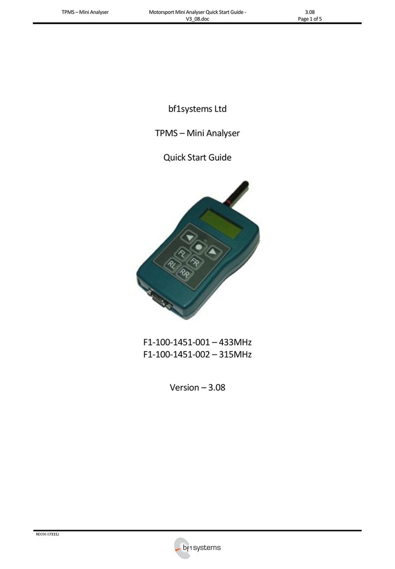
Tyre Pressure Monitoring System –Mini Analyser
User Manual
F1-100-1451-003 –433MHz TPMS Mini Analyser, Wireless
Version –1.06

Wireless Mini Analyser User Manual
Wireless Mini Analyser User ManualV1_06
1_04
2 of 32
RD096071112
Wireless Mini Analyser User Manual
Revision History
1 Modifications
Date
Modifications
Author
Version
Modified
Sheets
Approved
By
Date
Signed
03/07/2009
Document Creation
MRC
1_01
All
GMS
31/07/09
GMS
05/08/2009
Serial port configuration
added
Detailed description of
‘last’ command sequence
added
‘gencfg’ command
description added
Setup menu details
added
MAC_Addr update
command revised
MRC
1_02
8, 9, 10,
11, 12,
13, 15
JRS
06/08/2009
JRS
07/08/2009
Bootloader section covers
change of Mini Analyser
baudrate prior to
bootloading
MRC
1_03
16
JRS
07/08/2009
JRS
27/08/2009
‘last’ response updated.
Sensor data lines noe
begin with position
numbers 0:, 1:, 2:, 3: not
1:, 2:, 3:, 4:
MRC
1_04
9
GMS
27/08/09
GMS
26/10/2009
Front sheet added
Addition of batterystatus
splash screen to display,
sections 2.3.1 & 3.2.3
MRC
1_05
1,7,11
GMS
3/11/09
GMS
18/05/2015
Logo changed to
bf1systems on front page.
Safety advice added for
each device.
Inventory table added
Pictures of analyser & PC
module added
Batterycharger section
added.
USB mains power supply
section added.
Mini analyser battery
section added.
Attaching the antenna
section added.
Charger mw6288gs spec
page added.
USB power supply spec
page added.
FCC ID & IC comments
added to table
AE
1_06
1
4,5,6
7
12,13
8
9
11
12
31
31
28&30
AE
26/05/15
GU

Wireless Mini Analyser User Manual
Wireless Mini Analyser User ManualV1_06
1_04
3 of 32
RD096071112
1Modifications..........................................................................................................................................................................2
2Safety Advice.........................................................................................................................................................................4
2.1 MW6288 9V mains charger..........................................................................................................................................4
2.2 EMSA 5W USB Series Power Supply.........................................................................................................................5
2.3 Wireless mini analyser..................................................................................................................................................6
3Inventory................................................................................................................................................................................7
4System Overview..................................................................................................................................................................7
5Components..........................................................................................................................................................................7
5.1 Battery Charger.............................................................................................................................................................8
5.2 USB mains power supply..............................................................................................................................................9
5.3 Wireless Mini Analyser............................................................................................................................................... 10
5.4 Mini analyser battery.................................................................................................................................................. 11
5.5 Attaching the Antenna................................................................................................................................................ 12
5.6 Wireless Modules....................................................................................................................................................... 13
5.6.1 Wireless Module................................................................................................................................................. 13
5.6.2 Wireless PC Module........................................................................................................................................... 14
5.6.3Status Information.............................................................................................................................................. 15
5.6.3.1 Power LED...................................................................................................................................................... 15
5.6.3.2 Link LED.......................................................................................................................................................... 15
5.7 Analyser Overview..................................................................................................................................................... 15
5.7.1 Power Button...................................................................................................................................................... 15
5.7.2 Position Assignment Keys ................................................................................................................................. 15
5.8 Connectivity Set Up.................................................................................................................................................... 15
6Operation............................................................................................................................................................................ 16
6.1 Wheel Assignment..................................................................................................................................................... 16
6.2 Data Transfer.............................................................................................................................................................. 18
6.2.1 Command Transmission.................................................................................................................................... 18
6.2.2 ‘last’ Command................................................................................................................................................... 18
6.2.3 ‘setclear’ Command............................................................................................................................................ 19
6.2.4 ‘gencfg’ Command ............................................................................................................................................. 20
6.3 Setup Menu................................................................................................................................................................ 20
6.3.1 Power Settings.................................................................................................................................................... 21
6.3.2 Beep / LED 1...................................................................................................................................................... 21
6.3.3 Beep / LED 2...................................................................................................................................................... 22
6.3.4 System Info......................................................................................................................................................... 23
6.3.5 Contrast............................................................................................................................................................... 23
Channel Config................................................................................................................................................................... 24
7cParameters....................................................................................................................................................................... 24
7.1 Wireless Analyser Module......................................................................................................................................... 25
7.2 Wireless PC Module................................................................................................................................................... 25
7.3 Arguments .................................................................................................................................................................. 25
7.3.1 PAN_ID............................................................................................................................................................... 25
7.3.2 ED_MAC_Addr [n]/ C_MAC_Addr 1................................................................................................................ 25
7.3.3 Link_timeout ....................................................................................................................................................... 26
8Bootloader .......................................................................................................................................................................... 26
8.1 Mini Analyser Firmware Update................................................................................................................................ 26
9Wireless Analyser Module Specifications......................................................................................................................... 28
9.1 General....................................................................................................................................................................... 28
9.2 Communications......................................................................................................................................................... 28
9.3 Environmental............................................................................................................................................................. 28
Wireless PC Analyser Module Specifications........................................................................................................................... 30
9.4 General....................................................................................................................................................................... 30
9.5 Communications......................................................................................................................................................... 30
9.6 Environmental............................................................................................................................................................. 31
10 Charger MW 9V MW6288GS........................................................................................................................................ 32
10.1 Specifications.............................................................................................................................................................. 32
11 EMSA050100 USB power supply................................................................................................................................. 32
11.1 Specifications.............................................................................................................................................................. 32

Wireless Mini Analyser User Manual
Wireless Mini Analyser User ManualV1_06
1_04
Page 4 of 32
RD096071112
2 Safety Advice
2.1 MW6288 9V mains charger
WARNING!
Risk of electric shock
This product contains no serviceable parts and must not be opened.
Do not charge anyother type or chemistryof rechargeable battery
cells other than Alkaline, NiMH and NiCad.
This product must not be used outside.
Do not expose the charger torain or moisture to avoid the risk of fire
or electrical shock.
Always place the batterywith thepositive tip facing the top of the
charger-Incorrect polarity maycause a fire or explosion.
CAUTION!
Do not short the charging terminals
Do not operate the charger if it appears damaged in any way

Wireless Mini Analyser User Manual
Wireless Mini Analyser User ManualV1_06
1_04
5 of 32
RD096071112
2.2 EMSA 5W USB Series Power Supply
WARNING!
Risk of electric shock
This product contains no serviceable parts and must not be opened.
This product must not be used outside.
Do not expose the power supply to rain or moisture to avoid the
risk of fire or electrical shock.
CAUTION!
Do not use the power supply if it appears damaged in any way
Avoid extreme conditions such as extreme heat, cold, humidity or
direct exposure to the sun.

Wireless Mini Analyser User Manual
Wireless Mini Analyser User ManualV1_06
1_04
6 of 32
RD096071112
2.3 Wireless mini analyser
CAUTION!
Do not use the wireless mini analyser if there is any damage to the
battery terminal or wire.
Only use the power cables that have been supplied with the
wireless mini analyser.
NOTE
Remove battery from the device when not used for a long period of
time.

Wireless Mini Analyser User Manual
Wireless Mini Analyser User ManualV1_06
1_04
7 of 32
RD096071112
3 Inventory
The system will arrive with the following items:
Description
Qty
Wireless Mini Analyser
1
9V Battery Snap to 2.5mm Jack Charging Cable
1
280 mAh Ni-MH PP3 Rechargeable Battery
1
Detachable Antenna
1
Carry Case
1
Carrying Strap
1
Wireless Analyser Module
1
Wireless PC Module
1
Retractable USB cable
2
EMSA 5W USB Power Supply with 4 adaptors
1
Intercept MW6288GS Battery Charger
1
CD loaded with manualand software
1
4 System Overview
The Wireless Mini Analyser tool is designed for use on a vehicle production line as an emergency aid when the
standard wheel assignment process has failed. Under these circumstances the operator uses the Wireless Mini
Analyser to pass wheel sensor data to the production database.
5 Components
The Wireless Mini Analyser consists of a modified version of the standard bf1systems Mini Analyser hardware, but
using bespoke software.
The Wireless Analyser Module is a 2.4GHz-band radio modem that connects to the RS232 port located on the base
of Mini Analyser.
The Wireless PC Module is a 2.4GHz-band radio modem that connects to a PC serial port.
A rechargeable NiMH cell is supplied with the Wireless Mini Analyser which is charged via a jack on the side of the
analyser using the supplied charger.

Wireless Mini Analyser User Manual
Wireless Mini Analyser User ManualV1_06
1_04
8 of 32
RD096071112
5.1 Battery Charger
A 230V AC - 9/9.8 V DC Battery Charger is supplied with the Wireless Mini Analyser. The unit can charge 2
rechargeable 9V batteries and includes the following features: LED status display, micro controlling trickle charge
mode, a discharge function, and delta V detection
Intended use:
This product is intended for use only in dry interior rooms.
For use only with rechargeable Ni-Cd and Ni-MH batteries
Failure to follow safety instructions may cause fatal accidents, injuries, and damages to persons and property.
Connecting and operating
1. Connect either one or two PP3 Ni-Cd or Ni-MH batteries into the charging points. Ensure batteries to be
charged are of the same type. Do not mix battery types
2. Plug the Charger into a 230 V AC mains socket, and switch on
3. Select the operation mode with the mode switch: DISHARGE / CHARGE
Note: Discharging is only available at the right charging point.
Display: Red LEDs (CHARGE/READY) Illuminated
Batteries are charging.
Green LEDs (CHARGING/READY) illuminated.
Batteries are fullycharged.
Yellow LED (DISCHARGE) illuminated
Batteries are discharging.
The battery can also be charged via the supplied
charging cable.

Wireless Mini Analyser User Manual
Wireless Mini Analyser User ManualV1_06
1_04
9 of 32
RD096071112
5.2 USB mains power supply
The USB mains power supply is supplied with the purpose of supplying power directly to the wireless modules that
are used with the mini analyser.
The power supplyconverts 230V AC mains voltage into 5V DC at 1.0A
The power supply should only be used in conjunction with the USB cables that have been supplied with the mini
analyser.
For all safety advice please refer to the safety advice page which can be found at the start of this document.
Once the correct pin adaptor has been selected, slot it in at around a 30-45° angle then press down until it is locked
into place as shown in the images below
The USB cable should be inserted into the socket before the supply is connected to mains. See image 1 below.
The USB cable can now be plugged into the wireless module unit via the micro USB socket. See image 2 above.
Once everything is connected the plug can be connected to mains and power can be switched on.
The pin adaptor can be removed by pulling the release down as shown in the image below.
1
2

Wireless Mini Analyser User Manual
Wireless Mini Analyser User ManualV1_06
1_04
10 of 32
RD096071112
5.3 Wireless Mini Analyser
The Wireless Mini Analyser is fitted with a rechargeable battery in order to maximise the performance and versatility
of the device. A jack socket on the side of the unit allows it to be charged using the mains charger provided.
Pin 9 of the 9-way D-type fitted to the Wireless Mini Analyser has been wired to provide power for the Analyser
Module unit when in use.

Wireless Mini Analyser User Manual
Wireless Mini Analyser User ManualV1_06
1_04
11 of 32
RD096071112
5.4 Mini Analyser battery
The Wireless Mini Analyser will arrive with a rechargeable battery and detachable antenna placed within the battery
compartment as can be seen in the above image. The batteryis of the PP3 type and should always be replaced with
one of the same type. Failure to do so may affect the performance of the device.
The battery will have a plastic terminal cover or rubber grommet attached to it.
The terminal cover should always be placed on the batterywhen it is not being used.
The battery may contain charge but it is advised that the battery is placed into the battery charger supplied and left
until fully charged (Green LED illuminates).
Once the battery is fully charged and ready to be used, connect the battery to the battery snap ensuring the correct
polarity is observed.
To return the battery compartment
lid, simply push down until the
release button clicks back into place
Correct battery installation.
Battery snap polarity
Batteries should be disposed in accordance with local waste regulations. Do not incinerate.
To remove the battery compartment lid
Press the release clip and lift away.
The battery and antenna can be found stored
within the battery compartment.
It is advised that the battery terminal cover is placed onto the battery during transit to avoid
shorting of terminals.
- +
PUSH
PRESS
LIFT

Wireless Mini Analyser User Manual
Wireless Mini Analyser User ManualV1_06
1_04
12 of 32
RD096071112
5.5 Attaching the Antenna
The wireless mini analyser is supplied with a detachable antenna which can be found and stored in the battery
compartment.
Attach the antenna simplyscrew it clockwise onto the antenna connector located on top of the mini analyser.
The antenna should only be finger tight –Do not use any tools as this will result in damage to the antenna or
connector.
It is advised that the antenna is removed and stored away in the batterycompartmentwhen not in use.
Attaching Detaching

Wireless Mini Analyser User Manual
Wireless Mini Analyser User ManualV1_06
1_04
13 of 32
RD096071112
5.6 Wireless Modules
5.6.1 Wireless Module
The Wireless Module is fitted with a 9-way D-type, which connects directly to the 9-way D-type fitted to the bottom of
the Mini Analyser. When connected in this waythe Wireless Module is powered directlyfrom the Mini Analyser.
In order to make changes to the internal settings of the device the unit must be connected to the serial port of a PC
using a standard null modem serial cable (not supplied). When changing the internal settings the Wireless module
unit must be powered via the micro-USB connector on the side of the module. NOTE: The USB connector is solely
for the provision of power to the unit; no USB communication is supported.
USB Connector
Programming /
Configuration switch
2.5mm charge socket
Red Power LED
Orange wireless link LED

Wireless Mini Analyser User Manual
Wireless Mini Analyser User ManualV1_06
1_04
14 of 32
RD096071112
5.6.2 Wireless PC Module
The Wireless PC Module is fitted with a 9-way D-type, which can be connected directly to the 9-way D-type serial
connector on a PC. A straight through serial extension lead should be used to remotely connect the Wireless PC
module.
The Wireless PC Module settings maybe updated with the unit connected to the PC serial port.
The Wireless PC Module is powered via the micro-USB connector on the side of the unit. NOTE: The USB
connector is solelyfor the provision of power to the unit; no USB communication is supported.
USB Connector
Programming / Configuration switch
Orange wireless link LED
Red Power LED

Wireless Mini Analyser User Manual
Wireless Mini Analyser User ManualV1_06
1_04
15 of 32
RD096071112
5.6.3 Status Information
Both the Wireless PC Module and Wireless Analyser Module have 2 LEDs that are used for indicating the status to
the user. The red LED pertains to power while the orange LED relates to wireless link status.
5.6.3.1 Power LED
The power LED has three modes of operation:
Continuouslyon : Power on, unit initialising
Blink : Power on, initialisation completed ok, operating normally (0.3s on –2.7s off)
Off : No power
5.6.3.2 Link LED
The link LED has four modes of operation:
Fast flash : Initialising link, searching for device to pair with (0.5s on –0.5s off)
Double blink : Link established and operating correctly (0.2s on –0.2s off –0.2s on –1.4s off)
Blink : cParameter edit mode, no wireless activity (0.3s on –1.7s off)
5.7 Analyser Overview
5.7.1 Power Button
The Power Button is used to power on and off the Wireless Mini Analyser unit. With the unit powered off, pressing
and holding the Power Button will cause the unit to turn on. Upon power on the unit will display a number of
information splash screens, before displaying the main Sensor Assignment screen. The Current batterystatus will
be shown as part of the power on sequence, so that the user can verifythe unit is suitably charged prior to use.
The unit is powered off bypressing and holding the Power Button for longer than 2 seconds.
5.7.2 Position Assignment Keys
The position assignment keys provide the operator with the means to associate a wheel sensor with a given location
on the vehicle. For theWireless Mini Analyser, the Position Assignment Keys are the only functional keys.
5.8 Connectivity Set Up
The Wireless Analyser set-up provides a point-to-point link between a single End Device (Wireless Mini Analyser)
and a single Co-ordinator (Wireless PC Module). In order that units may automatically connect at power on devices
contain details of the units to which they may connect. Each end device is configured with the MAC address of a
single co-ordinator node, whilst co-ordinator nodes contain a list of up to 8 allowable end devices.
20 Character x4 Line
LCD Display
RS232 Interface
(9-way D)
AntennaConnector
PositionAssignment
Keys
Power Button
Tx/ Rx LED
Charge Connector

Wireless Mini Analyser User Manual
Wireless Mini Analyser User ManualV1_06
1_04
16 of 32
RD096071112
At power on the co-ordinator node (Wireless PC Module) enters pairing mode (fast flashing Link LED). In this mode
it listens for anyprogrammed device that is in range.
When an end device node (Wireless Analyser Module) is powered on it also enters pairing mode (fast flashing Link
LED).
When a compatible co-ordinator node and end device node are operating in pairing mode are within range of
each other, a link will be established. When the devices pair the link status LED on both devices will change
from fast flashing to double blink to indicate this. Once established the link will remain valid until one or other
of the devices times out due to lack of data transfer activity on the radio link.
By default the co-ordinator node Link_timeout is 15s, whereas the end device Link_timeout is 10s. It is intentional
that the end device Link_timeout is shorter than that of the co-ordinator Link_timeout.
If the end device node fails for any reason, then the co-ordinator node will revert to pairing mode after its
Link_timeout expires. This will allow a new end device node that is in the co-ordinator’s allowed list to be accepted.
The link establishment strategy is fully fault tolerant, and will automatically handle power cycling of devices in any
order, and will automatically re-establish a link in the event of an end device failure. If the co-ordinator node is lost
through power failure, the link will automaticallyrestart once power is re-applied.
6 Operation
Operation of the Wireless Mini Analyser falls into two parts, collection of the wheel sensor information using the Mini
Analyser itself, and gathering of the information stored in the Mini Analyser via the wireless link to the host PC.
6.1 Wheel Assignment
The purpose of theWireless Mini Analyser is to provide a convenient method for the assignment of wheel sensors to
their appropriate location on the car, should the normal automated process fail for any reason.
In order to position a sensor the operator should LF trigger the sensor via one of the Position Assignment Keys on
the analyser [FL] [FR] [RL] [RR]. When the sensor responds, and the Mini Analyser receives the RF datagram the
data is automatically assigned it to the appropriate corner based on the Position Assignment Key used to trigger the
sensor. When a sensor is positioned successfully a splash screen is displayed, together with a beep and flashing of
the Tx/Rx LED.
S
e
N
s
o
r
P
o
s
i
t
i
o
n
F
L
If an RF datagram is not received within 500ms in response to the LF trigger, then the Mini Analyser will
automatically reattempt to trigger the sensor again after a further 500ms (i.e.: 1s between LF trigger attempts). The
Mini Analyser will make up to 5 retries to LF trigger the sensor. If no RF datagram has been received after the fifth
retry, a splash screen will be displayed, accompanied by a beep and flashing of the Tx/Rx LED.
L
F
T
r
i
g
g
e
r
!
!
!
F
A
I
L
E
D
!
!
!

Wireless Mini Analyser User Manual
Wireless Mini Analyser User ManualV1_06
1_04
17 of 32
RD096071112
As each wheel is learned, the serial number of the sensor that has been assigned to the wheel will be shown on the
Mini Analyser display. Unassigned locations will display serial number ‘0’.
▲
F
L
:
2
0
1
3
8
1
5
5
6
9
▲
▲
F
R
:
0
▲
▲
R
L
:
0
▲
▲
R
R
:
0
▲
This process is repeated for each corner of the vehicle.
▲
F
L
:
2
0
1
3
8
1
5
5
6
9
▲
▲
F
R
:
2
0
1
3
8
6
3
3
2
4
▲
▲
R
L
:
0
▲
▲
R
R
:
0
▲
▲
F
L
:
2
0
1
3
8
1
5
5
6
9
▲
▲
F
R
:
2
0
1
3
8
6
3
3
2
4
▲
▲
R
L
:
2
0
1
3
7
6
9
2
0
5
▲
▲
R
R
:
0
▲
▲
F
L
:
2
0
1
3
8
1
5
5
6
9
▲
▲
F
R
:
2
0
1
3
8
6
3
3
2
4
▲
▲
R
L
:
2
0
1
3
7
6
9
2
0
5
▲
▲
R
R
:
2
0
1
3
7
3
3
7
6
0
▲
Should the set assignment fail, due to duplicating a serial number between locations, a splash screen is displayed,
together with a beep and flashing of the Tx/Rx LED. The operator need only relearn the corner in error to complete
the set.
S
e
T
E
r
r
o
r
D
u
p
l
i
C
a
t
e
S
e
r
i
a
l
F
L
R
L

Wireless Mini Analyser User Manual
Wireless Mini Analyser User ManualV1_06
1_04
18 of 32
RD096071112
6.2 Data Transfer
Transfer of the data collected by the Wireless Mini Analyser is achieved via the wireless serial link provided by the
Wireless PC Module andWireless Analyser Module. The wireless modules provide a transparent 19200-baud serial
link between the host PC and the Mini Analyser. When operating with the Wireless Modules the serial port should
be configured as follows:
Data Rate : 19200 baud
Data bits : 8
Parity : No
Stop bits : 1
Flow control : None
6.2.1 Command Transmission
Due to the single RF channel link between the host PC and the Wireless Mini Analyser, full-duplex serial
communication is not possible. The terminal interface within the Wireless Mini Analyser has been modified to
suppress the remote echo that is present in the standard firmware. As a result there is no requirement for the
terminal emulator,or other software, to waitfor an echocharacter from theWireless Mini Analyser.
If the Wireless Mini Analyser is used with a standard terminal program the entered characters will not be visible to
the user unless the terminal program is configured to provide a local echo. If remote echo suppression strategy is
not implemented then command transfers may fail due to clashes between transmitted and echoed characters on
the RF link.
6.2.2 ‘last’ Command
The current contents of the set buffer may be requested from the Mini Analyser at any time by use of the ‘last’
terminal command. In response to this command the Wireless Mini Analyser will transmit a fixed length data block
containing the collected data. As the Wireless Mini Analyser is generally intended for connection to a terminal
program, the data is transferred as ASCII characters.
The transferred data consists of 124 characters of header (2 lines of 62 characters), followed by 244 characters of
data (4 lines of 61 characters), regardless of sensor generation (G2 or G3). Appended to the collected data is a 7-
character line containing a checksum that is used to verify data integrity.
Pos Chan SerialNo Pact Tact RSSI RBL Mode RLRot TimeStamp (62 chars)
--------------------------------------------------------------------------------------------- (62 chars)
0: -- 1402246943 1000 23 54 236 0x41 0x00 1360360 (61 chars)
1: -- 1402246937 1025 24 54 236 0x41 0x00 1538230 (61 chars)
2: -- 0 10000 -40 0 0 0x00 0x00 0 (61 chars)
3: -- 0 10000 -40 0 0 0x00 0x00 0 (61 chars)
0xf372 (7 chars)
The CRC is generated by the CCITT algorithm G(x) = x16 + x12 + x5+ 1 with a 0x0000 register preload value. The
CRC is calculated over the 244 characters of the data payload.
On receipt of the data block at the host PC the data should be validated by means of the CRC. If the CRC validates
correctly, then the host PC should complete the data transfer by sending an ‘ack’ packet back to the Wireless Mini
Analyser. An ‘ack’ packet consists of the characters ‘ack’ followed by a linefeed. If the CRC fails to validate, then the
data maybe re-requested via the ‘last’ command.
The complete sequence for the ‘last’ command is shown as follows:
At the USER1> prompt, the host PC sends the ‘last’ command
On receipt of the ‘last’ command the Wireless Mini Analyser responds with the data and CRC block, followed by a
USER1> prompt
The data block received by the PC is validated by a CRC check
If the check is successful the PC responds with an ‘ack’ message at the USER1> prompt

Wireless Mini Analyser User Manual
Wireless Mini Analyser User ManualV1_06
1_04
19 of 32
RD096071112
On receipt of the ‘ack’ message the Wireless Mini Analyser will return to the USER1>, ready for the next host
command. USER1> last
Pos Chan Serial No Pact Tact RSSI RBL Mode RLRot Timestamp
-------------------------------------------------------------
0: -- 1402246943 1000 23 54 236 0x41 0x00 1360360
1: -- 1402246937 1025 24 54 236 0x41 0x00 1538230
2: -- 0 10000 0 0 0 0x00 0x00 0
3: -- 0 10000 0 0 0 0x00 0x00 0
0xf372
USER1> ack
USER1>
Note that as remote echo of data received at the Wireless Mini Analyser is suppressed due to the half-duplex
capability of the wireless link, the ‘last’ and ‘ack’ messages from the host PC will not appear on the terminal unless it
is configured to provide local echo.
In order to provide user feedback of reception of the ‘last’ command, the characters at the ends of the Wireless Mini
Analyser display screen toggle between up-arrow and down-arrow characters each time the command is received.
▲
F
L
:
2
0
1
3
8
1
5
5
6
9
▲
▲
F
R
:
2
0
1
3
8
6
3
3
2
4
▲
▲
R
L
:
2
0
1
3
7
6
9
2
0
5
▲
▲
R
R
:
0
▲
▼
F
L
:
2
0
1
3
8
1
5
5
6
9
▼
▼
F
R
:
2
0
1
3
8
6
3
3
2
4
▼
▼
R
L
:
2
0
1
3
7
6
9
2
0
5
▼
▼
R
R
:
0
▼
6.2.3 ‘setclear’ Command
The contents of the set buffer maybe cleared via the host PC at any time using the ‘setclear’ command.
This command is generally used once a complete set of wheel sensors has been learnt and transferred, in order to
clear the buffer ready for next use. In order for the host PC to verify that the command has been correctly received
and executed by the Wireless Mini Analyser it will respond with an ‘ack’ packet. An ‘ack’ packet consists of the
characters ‘ack’ followed by a linefeed.
On receipt and execution of the ‘setclear’ command the unit first switches to the battery status display screen, which
is splashed for 3 seconds. This allows the user to monitor the battery usage without the need to switch operating
modes.
B
a
t
t
e
r
y
S
t
a
t
u
S
<
#
#
#
#
#
#
#
#
#
#
#
#
#
#
>
U
p
B
a
c
k
l
i
g
h
t
D
o
w
N
The display will then return to the main sensor positioning screen, having had the displayed serial numbers reset to
zeros.
▼
F
L
:
0
▼
▼
F
R
:
0
▼
▼
R
L
:
0
▼
▼
R
R
:
0
▼

Wireless Mini Analyser User Manual
Wireless Mini Analyser User ManualV1_06
1_04
20 of 32
RD096071112
6.2.4 ‘gencfg’ Command
By default the Wireless Mini Analyser is configured to auto detect and decode RF datagrams from Ge1, Gen2 and
Gen 3 sensors. In some situations the user may wish to configure the unit to receive only sensors of a specific type.
This can be achieved via the ‘gencfg’ terminal command.
Sending the ‘gencfg’ command with no argument at the USER1> prompt will result in the current setting, and
available options being returned bytheWireless Mini Analyser:
USER1> gencfg
Current sensor gen configuration 4
Sensor gen configuration 0 = GEN1
Sensor gen configuration 1 = GEN2
Sensor gen configuration 2 = GEN3
Sensor gen configuration 4 = Auto
USER1>
To modify the setting the ‘gencfg’ command should be sent with the appropriate argument. The Wireless Mini
Analyser will respond with a message indicating the change has taken place.
USER1> gencfg 2
Sensor gen configuration 2 set
If the terminal is not configured for local echo then the information sent at the USER1> prompt will not be visible on
the terminal.
6.3 Setup Menu
The setup menu gives access to status and configuration information for the Wireless Mini Analyser. Pressing the
power button and left arrow button at the same time accesses the setup menu. The setup menu is entered at the
<Power Settings> menu page. Other available pages are accessed using the Left Arrow / Right Arrow navigation
buttons.
The setup menu can be exited by pressing and holding the Left Arrow navigation button. This will move the user to
the top level menu.
The <Battery Status> page indicates the current state of charge of the Mini Analyser internal battery, and also allows
the user to turn on and off the display backlight . The backlight state is toggled by pressing the power button.
Pressing the power button at the <RF Receive> top level menu page returns the user to the default sensor display
page.
Setup
System Info
Up Ok Down
Setup
Contrast
Up Ok Down
Setup
Channel Config
Up Ok Down
Setup
PowerSettings
Up Ok Down
Setup
Beep / LED 1
Up Ok Down
Setup
Beep / LED 2
Up Ok Down
RF Receive
Up Ok Down
Setup
Up Ok Down
BatteryStatus
<######## >
Up Backlight Down
Table of contents
Other bf1 systems Measuring Instrument manuals
