Bombard Commando C3 User manual

Tome 2 - Volume 2 - Teil 2 - Tomo 2
C 3 - C 4 - C 5
/ 8
F
R
A
N
C
A
I
S
1
AVERTISSEMENT
⚫LISEZ ATTENTIVEMENT CE MANUEL AVANT MISE EN SERVICE
DU BATEAU.
⚫LE MANUEL DU PROPRIETAIRE SE DIVISE EN DEUX TOMES QUI
DOIVENT ETRE CONSERVES ENSEMBLE.
NOTE :
LE MANUEL DU PROPRIETAIRE SE DIVISE EN DEUX TOMES:
- LE TOME 1
TRAITE D’UNE MANIERE GENERALE DES PRECAUTIONS
D’USAGE ET DES RECOMMANDATIONS A RESPECTER A
BORD DU BATEAU ET SUR L’EAU.
- LE TOME 2
TRAITE PLUS PARTICULIEREMENT DES CARACTERISTIQUES
TECHNIQUES ET DU MONTAGE DU BATEAU ET DE SON
EQUIPEMENT.
TOME 2
CARACTERISTIQUES TECHNIQUES - PROCEDURE DE MONTAGE
C3 - C4 - C5
SOMMAIRE
Page
Page
Etapes de la mise en service du bateau
2
Gonflage du bateau
6
Inventaire à l'ouverture de l’emballage
2
Pression
7
Montage du bateau
3 - 4
Dégonflage / pliage du bateau
8
Le système de gonflage
5
- Caractéristiques techniques
I - II
- Description générale
III - IV

/ 8
2
/ 8
F
R
A
N
C
A
I
S
3
LES GRANDES ETAPES DE LA MISE EN SERVICE DU BATEAU
La procédure de montage du bateau suit un ordre que nous vous engageons à respecter.
Procédez étape par étape en vous reportant à chaque fois aux pages indiquées pour les
explications de procédure.
PROCEDURE
PAGE
SECTION
1. faites l’inventaire des éléments qui composent votre
2
INVENTAIRE A
L’OUVERTURE
bateau, et apprenez à les reconnaître
I - IV
DESCRIPTION
2. activez les valves en position de gonflage
5
SYSTEME DE GONFLAGE
3. gonflez légèrement le flotteur
6
GONFLAGE DU BATEAU
4. assemblez le plancher et la quille dans le bateau
3 - 4
MONTAGE DU BATEAU
5. terminez le gonflage du bateau aux pressions
6
GONFLAGE DU BATEAU
d’utilisation
7
PRESSION
INVENTAIRE A L'OUVERTURE DE L'EMBALLAGE
ATTENTION
NE PAS UTILISER D'OUTIL TRANCHANT
(CUTTER, COUTEAU, ETC.)
L'emballage de votre bateau contient 1 flotteur +:
C 3
C 4
C 5
Plancher
nombre d’éléments
Alu
3 + 3
Alu
3 + 3
Alu
3 + 3
Longerons
2
2
2
Quille en bois 3 éléments
X
X
X
Manuel du propriétaire (2 tomes)
X
X
X
Mallette + nécessaire de réparations
X
X
X
Equipement standard
Pagaies
2
2
2
Indicateur de pression
1
1
1
Gonfleur
1
1
1
Fanion et hampe
1
1
1
Sac de transport
2
2
2
Vous pouvez équiper votre bateau d’accessoires en option (roues de transport, échelle de bain,
anneaux de levage etc.). Demandez à votre agent de vous conseiller.
NOTE :
SI VOUS SOUHAITEZ AJOUTER DES ANNEAUX DE LEVAGE (POUR
LA MISE SOUS BOSSOIRS), VOUS DEVEZ IMPERATIVEMENT LES
FIXER SUR LES FLOTTEURS ET NON SUR LE PLANCHER.

/ 8
4
MONTAGE DU BATEAU
Procédez au montage sur un sol propre et lisse.
SI LE BATEAU EST STOCKE A UNE TEMPERATURE INFERIEURE A 0°C,
LAISSEZ LE 12 H DANS UN LIEU TEMPERE (20°C) AVANT DE LE
DEPLIER.
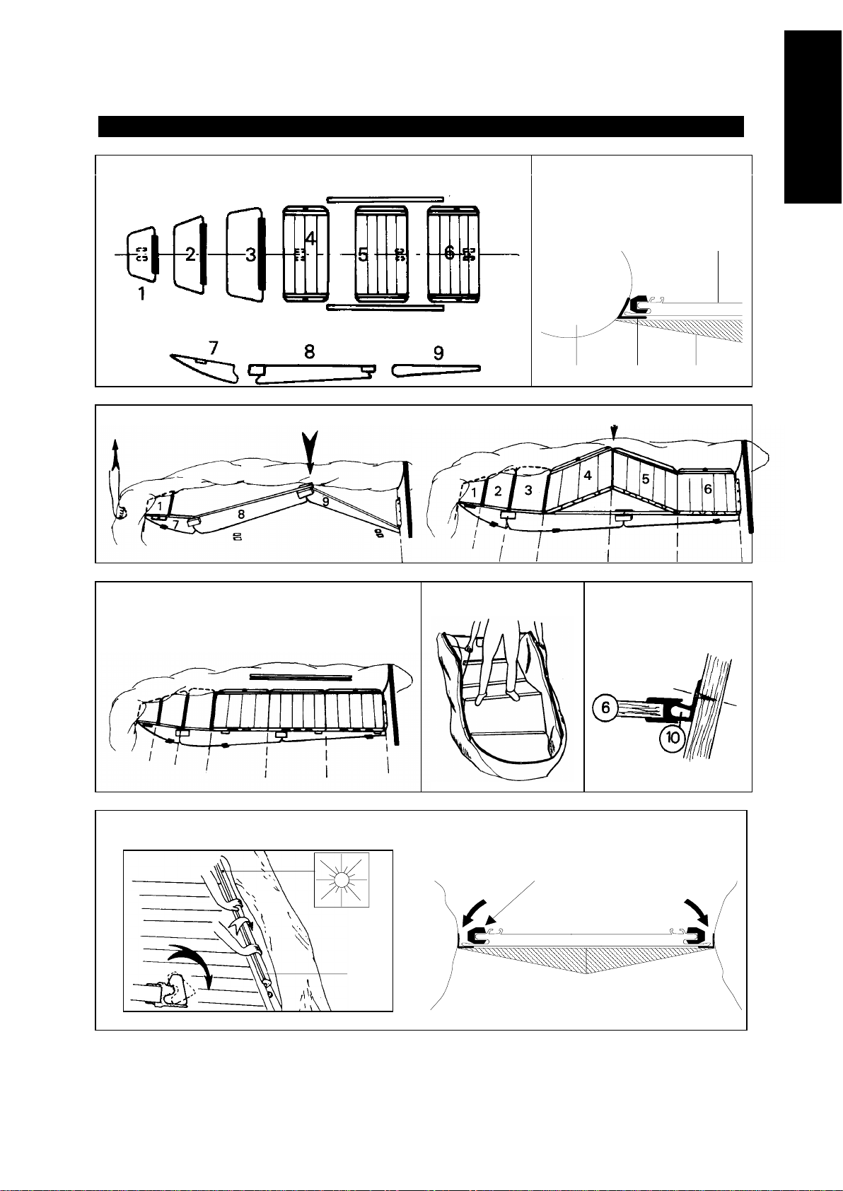
ASSEMBLAGE DU PLANCHER
•Mettez de la fécule dans les cornières (bande renforcée située entre le flotteur et le plancher)
pour faciliter la mise en place des éléments [fig 1-b].
ATTENTION
JAMAIS DE TALC.
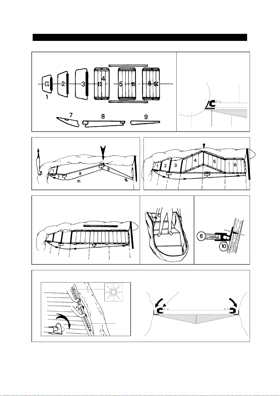
•Repérez bien les éléments et leur sens:
- Le plancher est composé de 3 éléments de plancher et 3 volets avant [fg 1].
- Repérez l'ordre des éléments à l'aide des étiquettes collées sur le coin avant droit de
chaque élément.
- Les volets ont un côté endroit et un côté envers. Le côté endroit est repérable par son
étiquette représentant le soleil. Si celle-ci venait à manquer, repérez-vous aux rayures des
profilés aluminium collés sur le volet; elles doivent être apparentes une fois le volet monté.
1. Gonflez légèrement le flotteur.
2. Introduisez le volet avant (1) dans la cornière avant [figure 1].
3. Introduisez l’élément de quille avant (7) sous le volet avant (1) jusqu’à ce que les taquets
soient en buttée [figure 2].
4. Emboîtez et mettez en toit l’élément central (8) et arrière (9) de la quille [figure 2].
5. Aplatissez le toit en veillant à ce que les éléments de quille restent bien alignés [figure 3].
Pour faciliter cette opération, il est préférable qu’une personne maintienne le nez du bateau
surélevé à environ 40 cm du sol (à défaut, installez une cale de même hauteur).
6. Emboîtez les éléments les uns dans les autres [figure 3]. Veillez à ce que l’élément arrière (6)
s’emboîte correctement contre le tableau arrière [figure 6].
7. Mettez en "toit" deux éléments de plancher [figure 3] après avoir vérifié que l'ensemble soit
bien aligné, que le plancher soit bien positionné dans les cornières à l’intersection du flotteur et
du fond, et que la quille soit bien positionnée dans ses guides.
8. Aplatissez le toit en montant dans le bateau et en tirant les saisines vers le haut pour éviter
de coincer le tissu [figure 5].
9. Installez les longerons comme indiqué ci-dessous.
MISE EN PLACE DES LONGERONS
Les longerons permettent de verrouiller le plancher et d’en rigidifier la structure, élément
essentiel pour la bonne navigabilité du bateau.
1. Positionnez les longerons sur le bord du plancher; le repérage du longeron doit rester sur le
dessus.
2. Engagez bien les longerons entre les butoirs des éléments 4 et 6 [figure 1 et 4] et
positionnez-les dans la cornière entre le flotteur et le plancher.
3. Faites pivoter les longerons sur eux-mêmes dans les cornières pour les enfoncer contre le
fond [figure 7].
4. Grâce à la structure auto-serrante du, les longerons se mettront définitivement en place
lors du gonflage des flotteurs.
/ 8
F
R
A
N
C
A
I
S
5
MONTAGE DU BATEAU
fig 1-A
fig 1-B
a- plancher b- flotteur
c- cornière d- fond
a
b c d
fig 2
fig 3
fig 4
fig 5
fig 6
fig. 7
12
11
12

/ 8
6
LE SYSTEME DE GONFLAGE
LE GONFLEUR
a. adaptateur
b. embout du tuyau
c. embase du tuyau
d. orifice de gonflage
a
b
cd
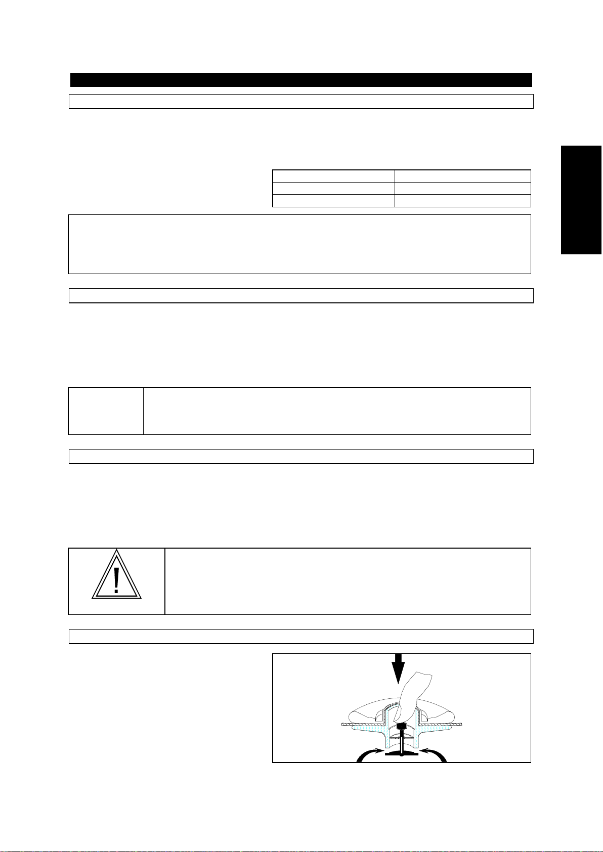
LES VALVES EASY PUSH
Pour activer les valves easy push:
Pour changer de position
En position de gonflage
En position de dégonflage
Poussez
La membrane est fermée, le
poussoir en position haute
La membrane est ouverte, le
poussoir en position basse
NOTE:
NE JAMAIS FORCER LORS DU VISSAGE : VOUS RISQUERIEZ DE DEVISSER
L’ENSEMBLE DU SYSTEME DE GONFLAGE INTERNE DE LA VALVE
L’INDICATEUR DE PRESSION

/ 8
F
R
A
N
C
A
I
S
7
GONFLAGE DU BATEAU
Activez toutes les valves en position gonflage.
Fixez l’embase du tuyau à l’orifice de gonflage
du gonfleur.
Pour bien gonfler votre bateau, il faut que le
gonfleur ait une bonne assise sur le sol.
Le bateau se gonfle rapidement si le gonfleur
est actionné en souplesse et sans précipitation.
ATTENTION
NE PAS UTILISER DE COMPRESSEUR OU DE BOUTEILLE A AIR
COMPRIME.
Vous pouvez utiliser le gonfleur électrique
ACCESS
en vente chez votre agent.
GONFLAGE DU FLOTTEUR
•Ajoutez l'adaptateur correspondant au diamètre de la valve semi-encastrée à l'embout du
tuyau du gonfleur.
•Procédez au gonflage du flotteur en équilibrant les pressions entre les différents
compartiments, jusqu'à ce que les cloisons (a) ne soient plus visibles (pression = 240 mb)
NE JAMAIS METTRE UN
COMPARTIMENT SOUS
PRESSION LES AUTRES
ETANT COMPLETEMENT
DEGONFLES
a
100 % 0 % 0 %
1
50 % 50 % 50 %
2
100 % 100 % 100 %
Le gonflage est terminé: vissez les bouchons des valves de gonflement.
NOTE :
Il est normal de constater une légère fuite d’air avant le vissage du
bouchon de valve.
SEULS LES BOUCHONS ASSURENT L'ETANCHEITE FINALE.
/ 8
8
PRESSION
La pression d’utilisation pour le flotteur est de 240 mb/ 3,48 PSI (milieu de la zone verte de
l’indicateur de pression).
Si votre bateau n’est pas équipé d’un indicateur de pression
ACCESS
, nous vous
recommandons de vous en procurer un chez votre agent. Il vous permettra une lecture rapide
et efficace pendant le gonflage. Sans indicateur de pression, arrêtez de gonfler dès que le
flotteur est suffisamment ferme pour que l’on ne puisse plus couder à la main les cônes à
l’arrière du flotteur.
La température ambiante de l’air ou de
Température ambiante
pression interne du
flotteur
l’eau influe proportionnellement sur le
+1°C
+4 mb / 0,06 PSI
niveau de la pression interne du flotteur:
-1°C
-4 mb / 0,06 PSI
Aussi, il est important de savoir anticiper:
Vérifiez et ajustez la pression des compartiments gonflables (en regonflant ou en dégonflant
selon le cas) en fonction des variations de température (surtout lorsque les écarts de
température sont importants entre le matin et le soir dans les zones particulièrement
chaudes) et assurez vous que la pression ne s’écarte pas de la zone de pression recommandée
(de 220 à 270 mb / zone verte).
RISQUE DE SOUS-PRESSION:
EXEMPLE: Votre bateau est exposé sur la plage en plein soleil (température=50°C) à la
pression recommandée (240 mb/3,48 PSI). Lorsque vous le mettrez à l’eau (température=20°C),
la température et la pression interne des compartiments gonflables vont conjointement baisser
(jusqu’à 120 mb) et IL VOUS FAUDRA ALORS REGONFLER jusqu’à regagner les millibars
perdus à cause de l’écart de température entre l’air ambiant et l’eau. Ainsi il est normal de
constater une diminution de pression en fin de journée lorsque la température extérieure
baisse.
NOTE :
Sous-gonflé, votre bateau manque de rigidité en navigation, offre de
mauvaises performances et risque de vieillir prématurément.
RISQUE DE SURPRESSION:
EXEMPLE: Votre bateau est gonflé à sa pression recommandée (240 mb/3,48 PSI) en
début ou fin de journée (température extérieure basse=10°C). Plus tard dans la journée, votre
bateau est exposé en plein soleil sur la plage ou sur le pont d’un yacht (température=50°C). La
température intérieure des compartiments gonflables peut alors s’élever et atteindre jusqu’à
70°C (flotteurs de couleur foncée notamment) entraînant un doublement de la pression de
départ (480 mb). IL VOUS FAUDRA ALORS DEGONFLER afin de revenir à la pression
recommandée.
ATTENTION
SI VOTRE BATEAU EST TROP GONFLE, LA PRESSION SOLLICITE DE
FAÇON ANORMALE LA STRUCTURE GONFLABLE POUVANT ENTRAINER
UNE RUPTURE D’ASSEMBLAGE.
EN CAS DE SURPRESSION

/ 8
F
R
A
N
C
A
I
S
9
VALVE EASY PUSH :
Libérez de l’air en appuyant sur le poussoir de la
valve
/ 8
10
DEGONFLAGE / PLIAGE DU BATEAU
1. Dégonflez le bateau.
2. Remettez les protections des valves pour le stockage.
3. Retirez les équipements divers
4. Retirez le plancher et la quille selon la procédure inverse de celle du montage.
5. Retirez les bouchons des vide-vite, et videz le bateau de l’eau qui pourrait s’y trouver
(séchez-le bien avant tout stockage prolongé).
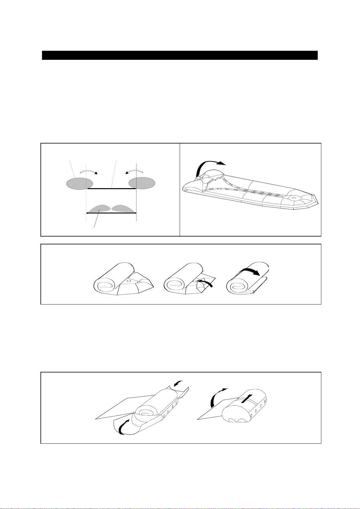
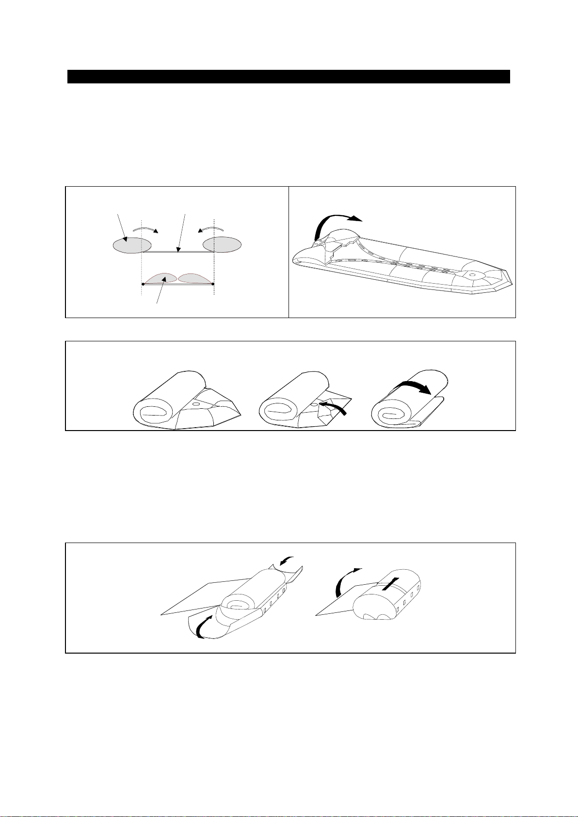
6. Repliez les 2 côtés du flotteur vers l'intérieur du bateau (A), amenez les cônes contre le
tableau (B), puis enroulez le bateau sur lui-même, autour du tableau (C). Recommencez
l’opération si vous constatez qu’il reste de l’air dans les flotteurs.
A
B
flotteur fond
flotteur dégonflé
C
Rangez le bateau dans ses sacs selon la procédure suivante (D):
.Dans un sac les éléments de plancher et la quille, dans l’autre le flotteur.
. Ramenez le dessus du sac et bouclez les deux sangles frontales.
. Fermez ensuite les sacs en tirant sur les cordons de serrage situés sur les côtés, en
veillant à ce que les accessoires ne dépassent pas.
. Pour finir, rangez le gonfleur dans la pochette extérieure.
D

/ 8
E
N
G
L
I
S
H
1
WARNING
⚫CAREFULLY READ THIS MANUAL BEFORE OPERATING YOUR
BOAT.
⚫THIS OWNER’S MANUAL IS IN TWO VOLUMES THAT MUST BE
KEPT TOGHETHER.
NOTICE:
THE OWNER'S MANUAL IS IN TWO VOLUMES:
- VOLUME 1
DEALS WITH OPERATING PRECAUTIONS AND SAFETY
RECOMMENDATIONS THAT MUST BE OBSERVED.
- VOLUME 2
DEALS WITH TECHNICAL SPECIFICATIONS AND ASSEMBLY
PROCEDURE OF THE BOAT AND ITS EQUIPMENT.
VOLUME 2
TECHNICAL SPECIFICATIONS - ASSEMBLY PROCEDURE
C 3 - C 4 - C 5
CONTENTS
Page
Page
Assembly procedure
2
Inflation
6
Check on unpacking
2
Pressure
7
Assembly
3 - 4
Deflation - folding the boat
8
Inflation system
5
- Technical specification
I - II
- General description
III - IV
/ 8
2
ASSEMBLY PROCEDURE
We recommend that you follow the specific order of the assembly procedure. Proceed step by step
and refer to the corresponding pages.
PROCEDURE
PAGE
SECTION
1. inventory the elements composing your boat,
2
CHECK ON UNPACKING
and learn how to recognise them
I –IV
DESCRIPTION
2. activate valves in inflating position
5
INFLATION SYSTEM
3. slightly inflate the main buoyancy tube
6
INFLATION
4. assemble the floorboard
3 –4
ASSEMBLY
5. finish inflation of the boat to the correct pressure
6 - 7
INFLATION / PRESSURE
CHECK ON UNPACKING
CAUTION
DO NOT USE A SHARP TOOL
The pack must contain: 1 buoyancy tube +
C 3
C 4
C 5
Floorboard
Number of pieces
Alu
3 + 3
Alu
3 + 3
Alu
3 + 3
Stringers
2
2
2
Wooden keel (3 elements)
X
X
X
Owner’s manual (2 volumes)
X
X
X
Repair kit
X
X
X
Standard equipment
Paddle
2
2
2
Pressure gauje
1
1
1
Foot-pump
1
1
1
Mast and pennant
1
1
1
Carrying bag
2
2
2
You can equip your boat with many optional accessories (transportation wheels, boarding ladder,
lifting rings etc.). Ask your dealer to advise you.
NOTICE :
IF YOU WISH TO ADD LIFTING RINGS, YOU MUST FIX THEM ON THE
BUOYANCY TUBE, NEVER ON THE FLOOR
/ 8
E
N
G
L
I
S
H
3
ASSEMBLY
Choose a smooth and clean surface
IF THE BUOYANCY TUBE WAS STORED AT A TEMPERATURE BELOW
0°C / 32°F, LEAVE IT AT 20°C / 68°F FOR 12 HOURS BEFORE
UNFOLDING.
FLOORBOARD ASSEMBLY
•Sprinkle some starch in the angle (joint of the buoyancy tubes to the bottom) to facilitate fitting.
CAUTION
NEVER USE TALCUM POWDER
•Make sure you identify the parts and direction in which they fit:
- The floorboard consists of 3 main sections and 3 sections in the bow [fig 1] you can identify
the good position of sections by the stickers located on the right corner of each section.
- The bow sections have an upside and a downside. The upside is identified by a label
representing the sun (11).
1. Slightly inflate the tube
2. Insert the bow section (1) into the angle at the bow.
3. Insert keel element (7) under element (1) until stop blocks get fixed [fig.2]
4. fit element (8) and (9) of the keel as an apex (in a tent-like position) [fig.2]
5. carefully flatten this apex so that the two elements are aligned. Another person can help raising
the bow of the boat up to 40 cm; otherwise, you can settle the bow of your boat on a 40 cm high
spacer that you will remove once assembly is over.
6. Respecting the order : slide element (2) against element (1), element (3) against element (2)
then slide element (6) against the transom retaining batten (10) [fig 6], and position elements (4) and 5
as an apex. [fig.3]. IMPORTANT: Check the good position of the keel into its blocks.
7. Flatten the apex by standing on it (in the boat) and pulling the lifelines to prevent the fabric being
pinched [fig. 5].
8. Assemble the stringers (see instructions bellow).
ASSEMBLY OF THE STRINGERS
The stringers are essential to good working of the boat: they lock the floorboard together and rigidify
its structure.
1. Position the stringer on the edge of the floorboard. The reference mark on the stringer must
remain on top (the thicker part should be towards the top) [fig. 7].
2. Fit the stringers between the two buffers of sections 4 and 6 [fig. 4 - 7].
3. Rotate the stringer in the angle so as to press them against the bottom [fig. 7].
4. Because of the self-locking system of the floorboard, the stingers will fit into place once the
buoyancy tube is inflated.
/ 8
4
ASSEMBLY
fig 1-A
fig 1-B
a- floorboard b- tube
c- angle d- bottom
a
b c d
fig 2
fig 3
fig 4
fig 5
fig 6
fig. 7
12
11
12

/ 8
E
N
G
L
I
S
H
5
INFLATION SYSTEM
THE FOOT PUMP
a. connecting tip
b. hose end piece
c. hose base
d. outlet for inflation
a
b
cd
THE EASY PUSH VALVES
To activate the easy push valves:
To change position
In inflating position
In deflating position
Push
The membrane is closed, the knob
is up
The membrane is open, the knob
is down
NOTICE:
TO SCREW OR UNSCREW THE VALVE CAPS, TURN WITHOUT
PRESSING OR FORCING (THIS COULD UNSCREW THE INNER VALVE
SYSTEM).
THE PRESSURE GAUGE

/ 8
6
INFLATION
Activate all valves into inflation position.
Fit the hose to the foot-pump.
To inflate your boat properly, the bottom side of
the foot-pump must rest on a flat ground.
Pump evenly to inflate rapidly.
WARNING
DO NOT USE A COMPRESSOR OR A BOTTLE OF COMPRESSED AIR
You can us the electrical air pump ACCESS (ask your Dealer).
TO INFLATE THE BUOYANCY TUBE
•Insert the pump hose end piece (add the correct connecting tip for the semi-recessed valve)
•Inflate (pressure = 240 mb, reefer to PRESSURE section) making sure that each compartment is
equal. When correctly inflated, the internal bulkheads (a) are not visible.
NEVER COMPLETELY
INFLATE A
COMPARTMENT TO FULL
PRESSURE IF OTHER
COMPARTMENTS ARE
TOTALLY DEFLATED
a
100 % 0 % 0 %
1
50 % 50 % 50 %
2
100 % 100 % 100 %
Inflation is over: fit the valve caps tight (clockwise).
NOTICE :
A slight air-leak before screwing the valve caps is normal.
ONLY THE VALVE CAPS CAN ENSURE FINAL AIR TIGHTNESS.
/ 8
E
N
G
L
I
S
H
7
PRESSURE
The correct pressure for the buoyancy tube 240 mb/3,48 PSI
If your boat is not equipped with a ACCESS pressure indicator, we recommend that you purchase one
from your Dealer. This will permit a quick and efficient control of the pressure during inflation. Without
a pressure indicator, stop inflating when the foot-pump gets difficult to operate, and the boat is
« hard » (you should not be able to bend the cone ends).
Ambient temperature of air and water
Ambient temperature
tubes’ internal pressure
have an effect on the boat’s internal
+1°C / +1,8°F
+4 mb / 0,06 PSI
pressure
-1°C / -1,8°F
-4 mb / 0,06 PSI
Therefore, it is important to anticipate:
Because of temperature variations (especially when this variation is important between the beginning
and the end of the day, in hot areas) check and adjust the pressure in the inflated compartments by
inflating or deflating. Be sure that pressure remains within the recommended zone, between 220
mb/3,10 PSI and 270 mb/3,85 PSI (green area).
RISK OF UNDERPRESSURE
EXAMPLE: Your boat is in direct sunlight on the beach (temperature =50°C/122°F) at
recommended pressure (240 mb/3,48 PSI). after putting it in the colder water (temperature
=20°C/68°F), the internal temperature and pressure of the tubes will both drop (up to 120 mb/1,7
PSI) and YOU WILL HAVE TO INFLATE AGAIN until you regain the lost pressure due to the
difference in temperatures. Therefore, a loss of pressure at the end of the day when ambient
temperature drops is perfectly normal.
NOTICE :
Proper inflation is critical to the performance of the boat. It is the pressure in
the tubes that gives your boat the necessary rigidity to perform well. Under-
inflation causes improper flexing of the tubes which will result in stress and
chafe
RISK OF OVERPRESSURE
EXAMPLE: Your boat is inflated to the recommended pressure (240 mb/3,48 PSI) at the
beginning of the day (low ambient temperature =10°C/50°F). Later in the day, your boat is in direct
sunlight on the beach or on a yacht’s deck (temperature =50°C/122°F). Internal temperature of all
inflated compartments can then increase and reach up to 70°C/158°F (especially for dark-coloured
tubes). The consequence will be a doubling of previous pressure (480 mb/6,8 PSI). YOU WILL THEN
HAVE TO DEFLATE until you reach the recommended pressure.
WARNING
WHEN YOUR BOAT IS OVER INFLATED, PRESSURE BECOMES TOO
STRONG FOR THE INFLATABLE STRUCTURE, AND COULD CAUSE A
BREAK IN THE FABRIC ASSEMBLY
IN CASE OF OVERPRESSURE
EASY PUSH VALVE :
Deflate by pressing the spring loaded
button.
/ 8
8
DEFLATING / FOLDING THE BOAT
1. Deflate the boat.
2. Replace the valve protections.
3. Remove paddles and equipment.
4. Remove the floorboard and keel.
5. Empty the boat of all water and sand by opening the self-bailers, dry it.
6. Fold in the 2 sides of the main buoyancy tube (A), fold the cones onto the transom, then roll up
the boat around the transom (C). Start again if you feel there is still some air left in the tubes.
A
B
buoyancy tube floor
tube deflated
C
Stow the boat in its bags as follows (D):
. In the first bag, stow the floorboard sections and keel, in the second the buoyancy tube.
. Close the bag and fasten the two front straps.
. Tighten the side ropes (make sure that all equipment stays inside).
. To finish, store the foot-pump in the front pocket.
D
/ 8
E
S
P
A
Ñ
O
L
1
ADVERTENCIA
⚫LEER CUIDADOSAMENTE ESTE MANUAL ANTES DE PONER
EN SERVICIO SU EMBARCACIÓN.
⚫EL MANUAL DEL PROPIETARIO ESTÁ DIVIDIDO EN DOS
TOMOS QUE DEBEN GUARDARSE JUNTOS.
NOTA:
EL MANUAL DEL PROPIETARIO SE DIVIDE EN DOS TOMOS:
- EL TOMO 1
TRATA DE MODO GENERAL DE PRECAUCIONES DE USO Y
CONSEJOS A TENER EN CUENTA A BORDO DE LA
EMBARCACIÓN Y EN EL AGUA.
- EL TOMO 2
TRATA MÁS DETALLADAMENTE DE LAS CARACTERÍSTICAS
TÉCNICAS Y DE MONTAJE DE LA EMBARCACIÓN Y SU
EQUIPAMIENTO.
TOMO 2
CARACTERÍSTICAS TÉCNICAS - MONTAJE
C3 - C4 - C5
ÍNDICE
Pagina
Pagina
Fases de la puesta en servicio de la
embarcación
2
Hinchado de la embarcación
6
Presión
7
Inventario al abrir el embalaje
2
Deshinchado / plegado de la
Montaje de la embarcación
3 –4
embarcación
8
El sistema de hinchado
5
- Características técnicas
I –II
- Descripción del conjunto
IIII - IV
This manual suits for next models
2
Table of contents
Languages:
Other Bombard Boat manuals


