Service Manual
ALX 720
Release 11/2003 Page 9 Adjustment
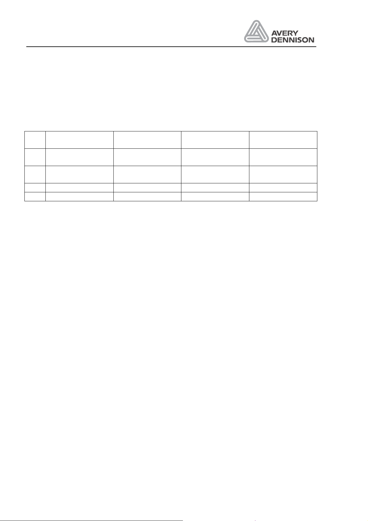
Sensor Connector Adjustment condition Pot Value /
Test point Para
meter Display
value
Label sensor CN15 without material in label
sensor Pot. P7 7 Pxxx 7
(Full size) with material >7
Adjustment Without Material in the label sensor (only backing paper):
For adjustment select the function OTHR/SCHK/Pxxx and turn the po-
tentiometer P7 (I/O-board) to get the display value P7.
With material (label) in the label sensor:
A display value of >P7 should be shown.
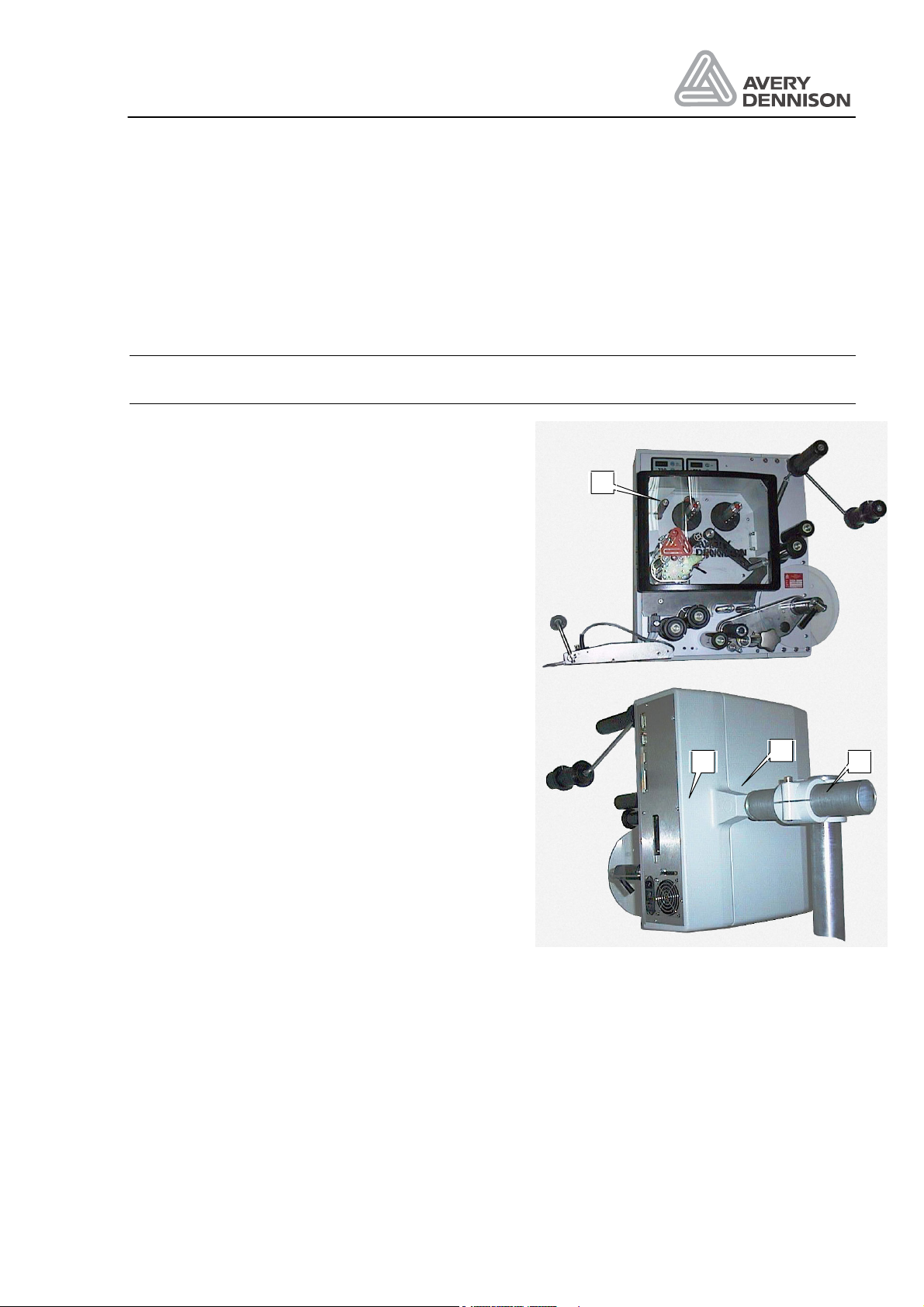
3.3 Loop sensor
Function The sensor measure the position of the dancer arm. Is the label loop not
filled, so the dancer arm is not in the home position, the printer starts
printing. If the loop is nearly empty a signal is generated to inhibit the
dispenser.
Location The loop sensor is mounted inside the machine at the dancer arm.
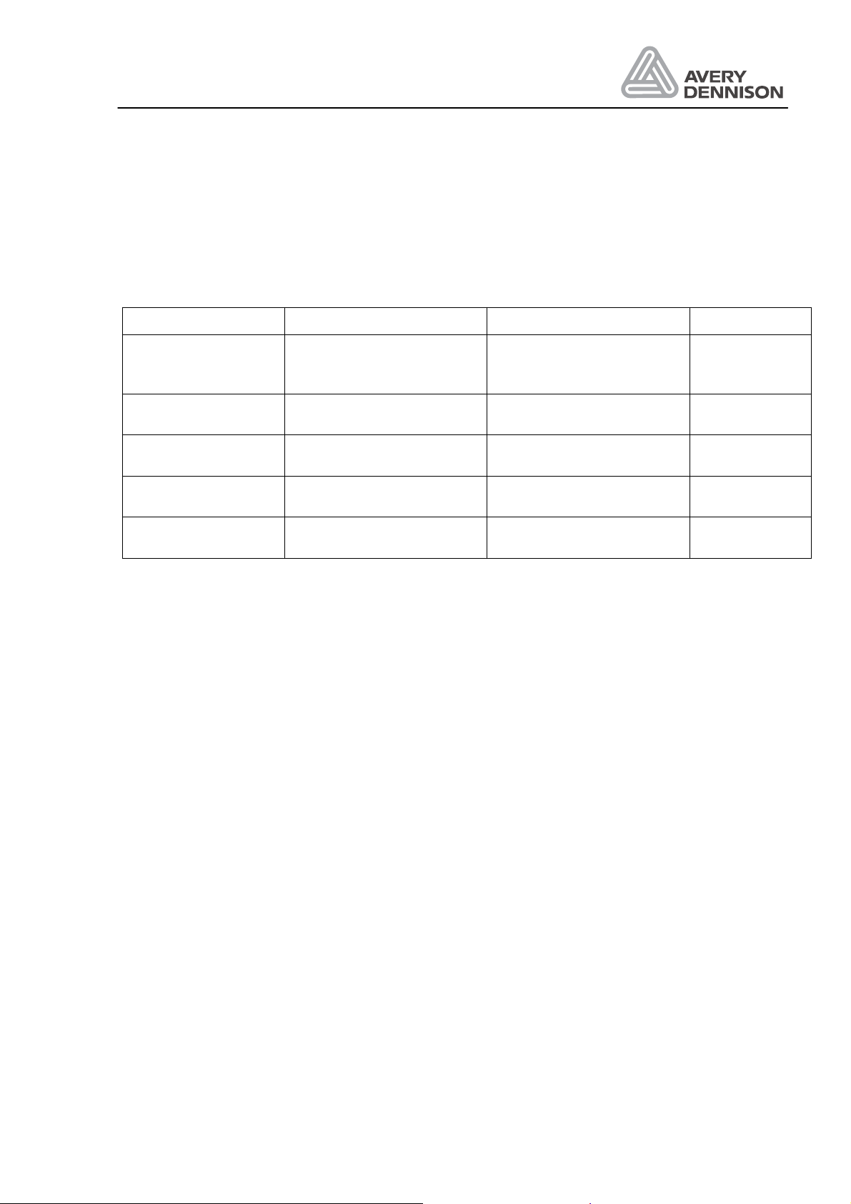
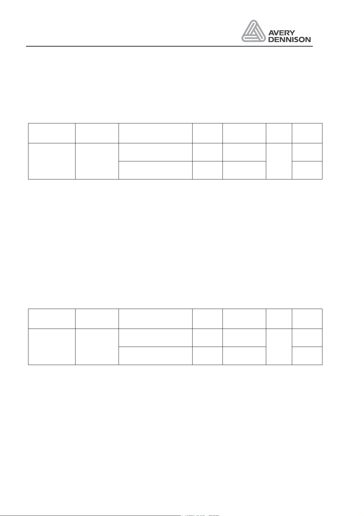
Sensor Connector Adjustment condition Pot Value / Test
point Para
meter Display
value
Loop sensor
CN13 Dancer arm in home posi-
tion Pot. P5 LH: 85
RH: 65 Rxxx LH: 85
RH: 65
Dancer arm at end posi-
tion <240
ca. 150
¯Before starting the adjustment be sure that the white wedge angle is
mechanical correct adjusted. In the home position of the dancer arm the
thick part of the wedge angle should be positioned in the sensor.
Adjustment Loop sensor in home:
For adjustment select the function OTHR/SCHK/Rxxx and turn the Po-
tentiometer P5 (I/O-board) until the value R85 is shown for a left hand
machine or R65 for a right hand machine.
Loop sensor in end position:
The value should so high as possible but not higher than R240.
¯The values itself are not important, but the
difference between the home and the end value should be so high as
possible.
¯The trigger points SW01 (Start of print)
and SW02 (Inhibit signal for dispenser) has to be set in the sub menu
SYSP.