AVF CML8360-F User manual
CML8360-F Leaflet No. 464513 rev00
English Language
##
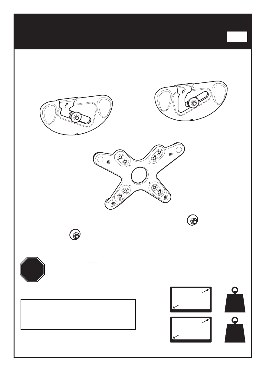
32"
81cm
STOP
Read through ALL instructions before commencing installation.
If you have any questions about this product or issues with installation
contact the customer services help line before returning this product to
the store. See www.cus.avfgroup.com/p/CML8360-A
AVF Incorporated. 3187, Cornerstone Drive, Eastvale, CA 91752, USA
88lbs
40kg
80"
203cm 121lbs
55kg
TVs up to
TVs up to
CUSTOMER SERVICES HELP LINE NUMBER:
1-800 667 0808 (USA)
=
=
Assembly Overview
Fit Screen Adaptor / Hangers to TV
Fitting the Wall Bracket
Hanging the TV
Retain all packaging in case the bracket needs to be returned.
Contents may vary from photography/ Illustrations.
You will not need all these parts, so expect there to be some left over depending upon the
specification of your TV.
This product is intended for indoor use only. Use of this product outdoors could lead to
failure and personal injury.
It is the responsibility of the installer to ensure that the mounting wall is of a suitable
standard and void of any services (eg gas, electricity, water etc).
AVF accept no responsibility for any damage or loss caused by installing this product in a
sub standard wall.

Index
Marking Wall For Drill Points
5
Assemble Positioning Template
3
Fit Adaptor to TV
2
Measure the TV fixing holes Width and Height
1
Determine Bracket Hole Centers
4
Fitting the Wall Bracket
6
Fitting the Wall Bracket Covers
7
Hanging the TV
8
No Adaptor Required
Adaptor Required
Marking Wall For Drill Points
Assemble Positioning Template
Fit Screen Hangers to TV
Determine Bracket Hole Centers
Fitting the Wall Bracket
Fitting the Wall Bracket Covers
Hanging the TV
13
10
12
11
14
15
9
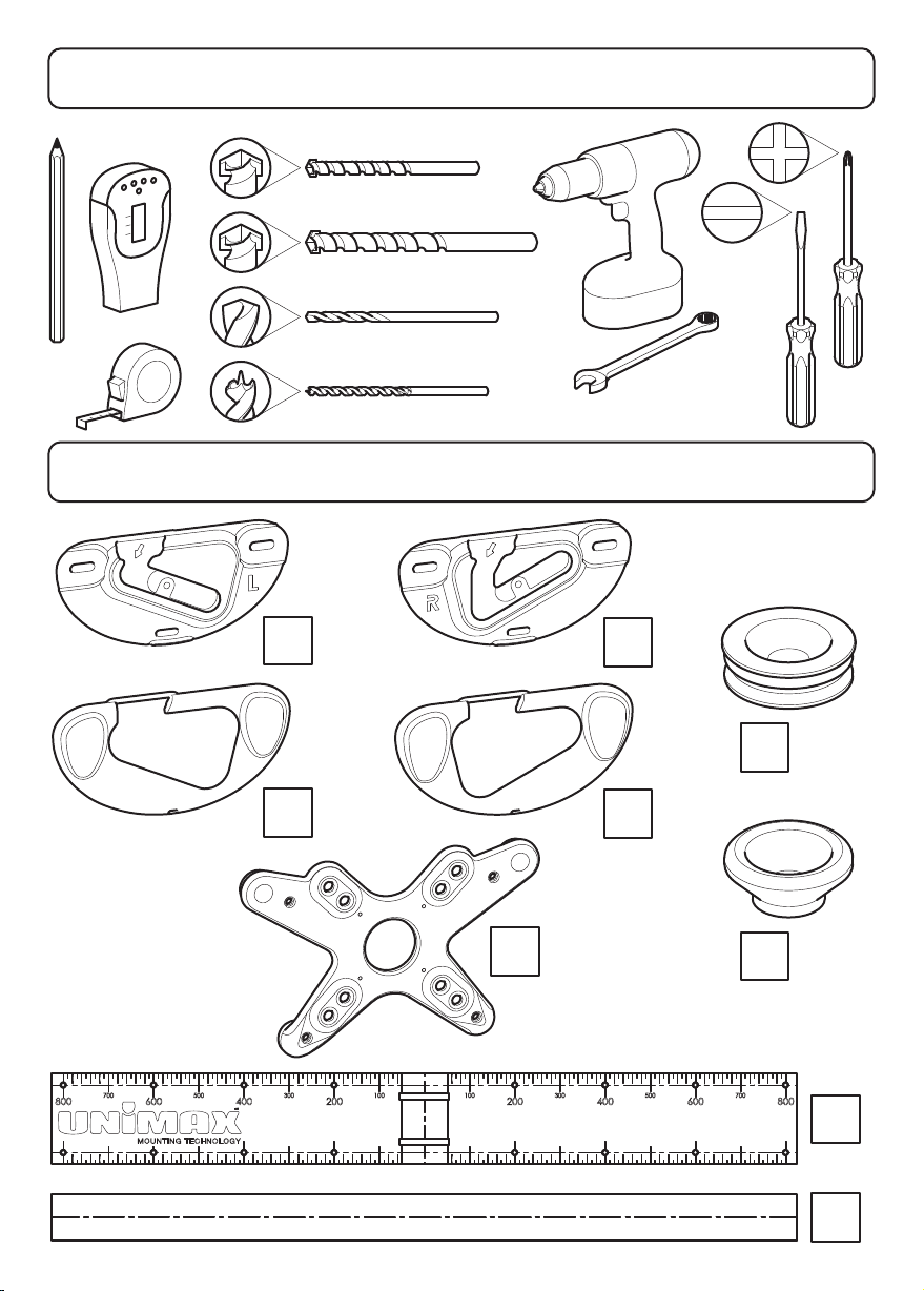
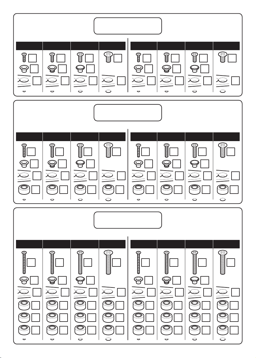
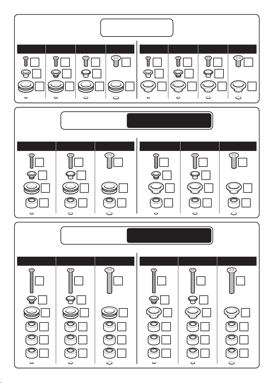
Boxed Parts
Tools Recommended
Stud Finder
Ø3mm (1/8") Wood
Ø10mm (25/64") Masonry
Ø5.5mm (7/32") Masonry
Ø3.5mm (9/64") Metal
A1
A
U2
U1
B1
B
Dx2
Cx2
V

TV Screws, Reducers and Spacers
F1x4
F2x4
F3x4
E1x12
E2x4
Hx4 Jx8
Lx2 Mx4 Nx4 Ox2
Px2
Qx2 R T
S
16mm
M5
25mm
M5
45mm
M5
16mm
25mm
45mm
M6 M6 M6
M8 M8 M8
16mm
25mm
45mm
G4x4 G5x4 G6x4
G7x4
G10 x4
G8x4
G11 x4
G9x4
G12 x4
25mm
M4
45mm
M4
16mm
M4
G1x4 G2x4 G3x4
You can only
use these
screws with
Adaptor V

!
Take Care
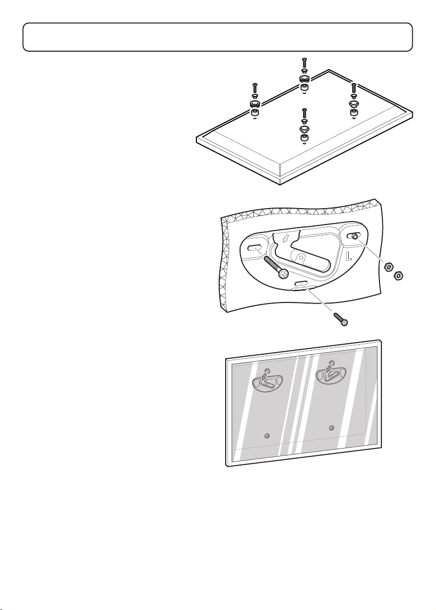
Remove the Wall Bracket Covers and keep for step 7 or 14
i
ii
Wall bracket covers A1 & B1 are removed in the same way.

Measure the TV fixing holes Width and Height
1
TV Fixing
Holes
75 or
100mm
75 or 100mm
X
Y
If width X and height Y are not equal to 75mm or 100mm and
are less than 200mm, STOP installation now and contact the
customer help line
!
You are provided with 4 diameters of TV fixing screws, M4, M5, M6 and
M8. Determine the screw diameter that fits and remember for step 2 or 9.
G7-G9M8 =M6 =
M4 =
G10-G12
X = 75 or 100mm
Adaptor
Required Y = 75 or 100mm
X = 200mm to infinity
No Adaptor
Required Y = 200mm to infinity
TV Fixing
Holes
200mm
to infinity
200mm to infinity
X
Y
G1-G3G4-G6
M5 =
With or Without Adaptor
The width and height of your TV fixing holes will determine if you need to
use the adaptor supplied.
With Adaptor
Follow steps 2 - 8
Without Adaptor
Follow steps 9 - 15
88lbs
40kg
121lbs
55kg
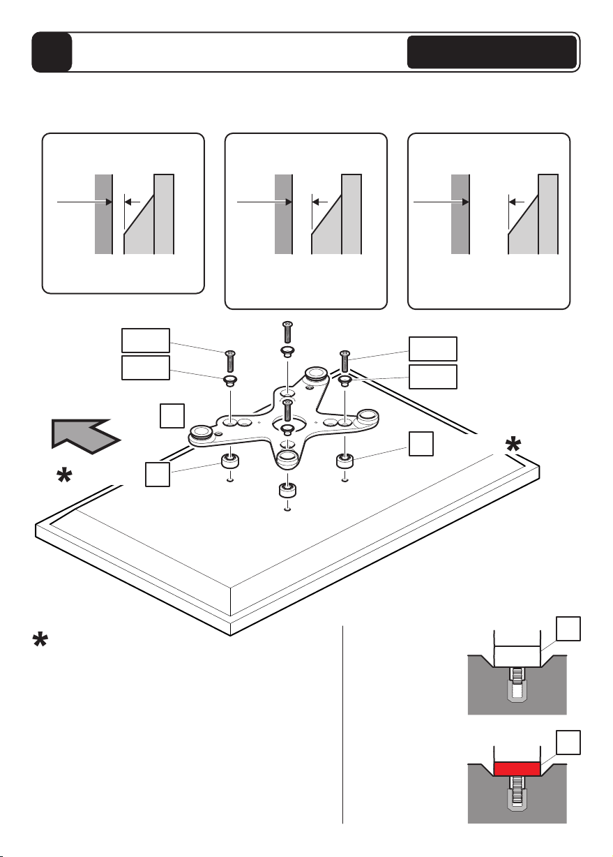
Fit Screen Hangers to TV
2
Once you have established which screw diameter you need for your TV you will need to choose
which wall spacing you require. Check the back of your TV and use the OPTION that fits your TV.
Please see page opposite for more details.
OPTION 1
20mm Wall Space
OPTION 2
30mm Wall Space
OPTION 3
50mm Wall Space
Suitable for TVs with a flat
back and no obstructions
Suitable for TVs with small
to medium obstructions eg
power supply, mouldings etc
Suitable for TVs with large
obstructions eg power
supply, mouldings etc
20mm 30mm 50mm
TV TV TV
Top
Bottom Fixings
If required
Top Fixings
F1-F3
G1-G12 G1-G12
If required
F1-F3
E2
TV
TV
Problem
Not enough screw
engagement
Solution
Red spacer
has replaced
spacer
E2
E1
E1
In certain circumstances it may be necessary to use
red spacer E2 as either a replacement or addition to
spacer E1.
When is it necessary to use red spacers E2?
It is recommended that when fitting Adaptor V to your
TV you have at least 5-10mm of screw engagement.
In certain circumstances you may need to use red
spacers E2 as either a replacement, or together with
spacers E1 to achieve this. Whenever you use red
spacers E2 you must use all 4 provided.
If required E1
If required
E1
V
With Adaptor
E1E1E1E1E1E1E1E1
E1E1E1E1E1E1E1E1
E1E1E1E1E1E1E1E1
F1F2F3F1F2F3
G3G3
G6G6G9G9G12 G12
E1E1E1E1
E1E1E1E1
F1F2F3
G2G5G8G11
F1F2F3
G2G5G8G11
V
F1F1F2F2F3F3
G1G1G4G4G7G7G10 G10
Top Fixings
M4 M5 M6 M8
Bottom Fixings
M4 M5 M6 M8
Top Fixings
M4 M5 M6 M8
Bottom Fixings
M5 M6 M8
Top Fixings
M5 M6 M8
Bottom Fixings
M5 M6 M8
V V V V V V V
V V V V V V V V
V V V V V V V V
M4
M4 M4
OPTION 1
20mm Wall Space
OPTION 2
30mm Wall Space
OPTION 3
50mm Wall Space
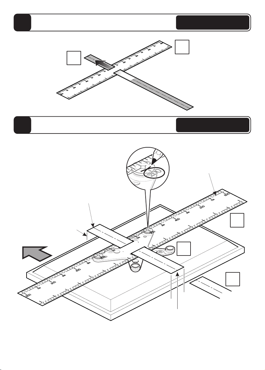
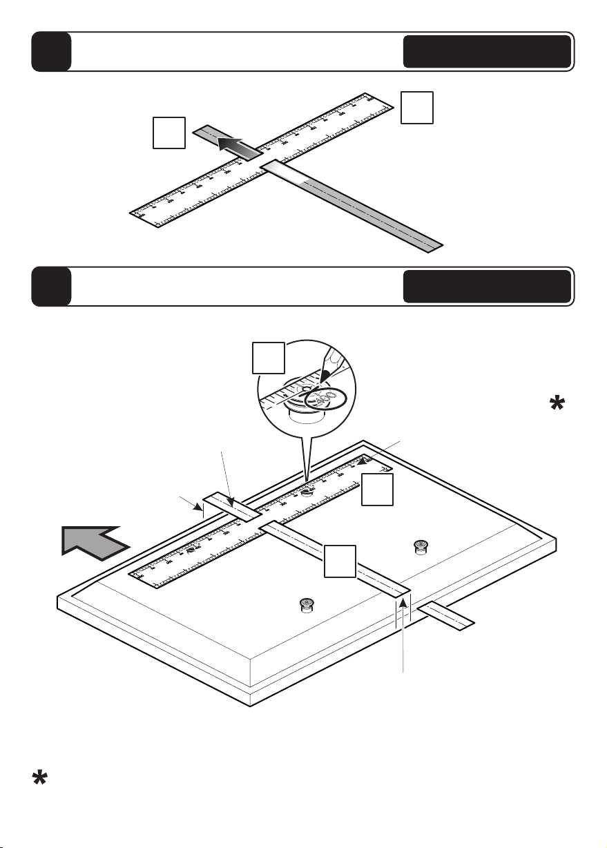
Assemble Positioning Template
3
U2
U1
Determine Bracket Hole Centers
4
Top
Lay the template on the back of the TV and follow the instructions below.
Cut the template U2 so it is flush with
the bottom of your TV so that when the
template is on the wall you can see
exactly where your TV will be vertically
(distance from the floor and ceiling).
U1
U2
Place the top row of holes on
template U1 over adaptor V.
Mark off the 200 centers Top row holes
V
The center line of the
template U2 represents
the center of your TV.
Line up with top
of the screen.
With Adaptor
With Adaptor
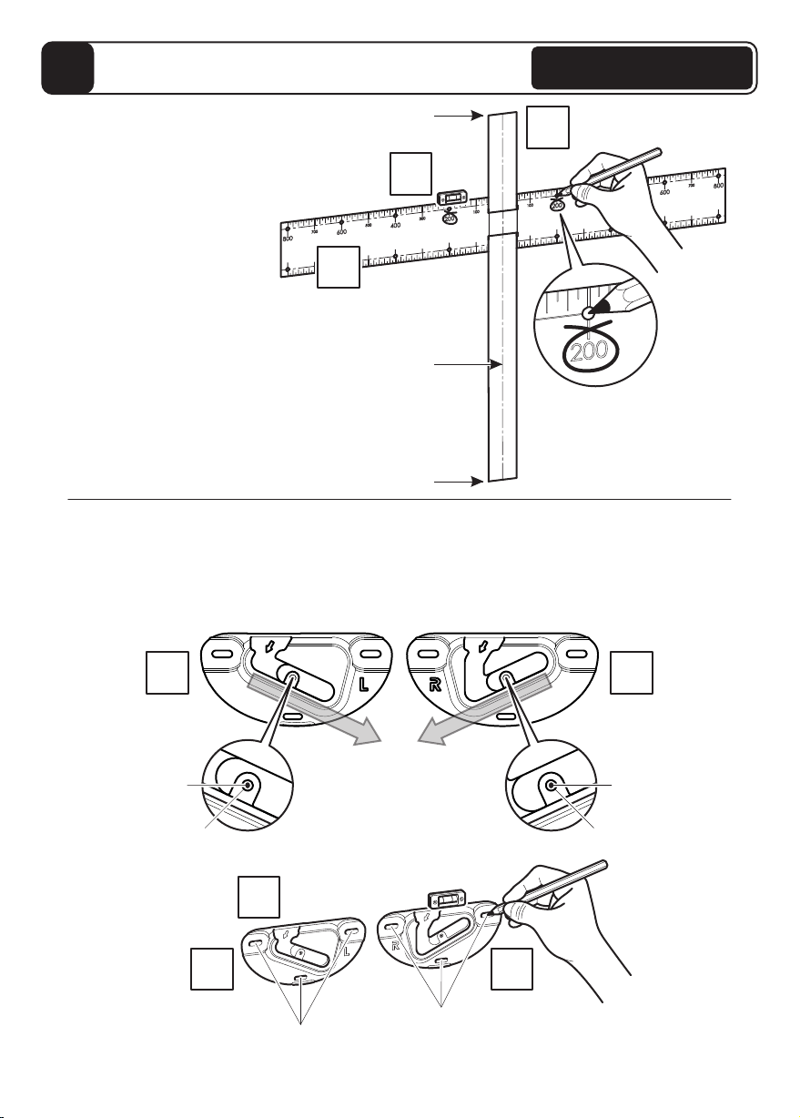
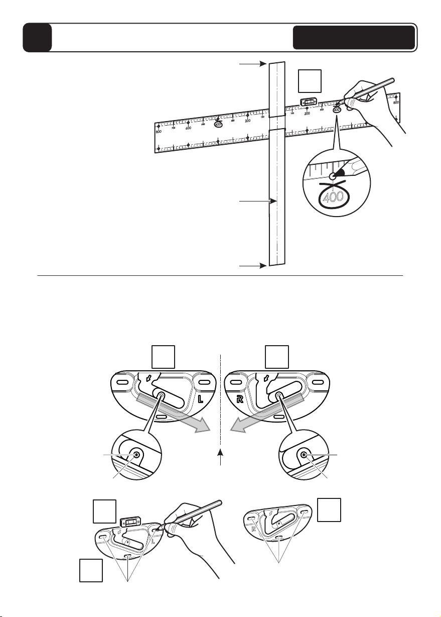
Marking Wall For Drill Points
5
Use your template to mark
two points on the wall.
Represents the
top of your TV.
T
Represents the
bottom of your TV.
Represents the
center of your TV.
DRILL POINTS
T
Next, use the Wall Brackets and as a template and position them over the appropriate
PENCIL MARKS you have made, so that the mark is in the middle of the
CENTRAL HOLE of the Wall Bracket. Ensure the bracket is level and mark the three
DRILL POINTS with a pencil. Repeat for other bracket.
A B
Drill six 3mm pilot holes and select appropriate fixings (see section 6)
B
DRILL POINTS
A B
A
Before marking the wall,
determine the wall type that
you have (i.e. Solid Wall/
Drywall/Wood Stud/
Metal Stud).
Ensure the drilling area is
free from mains services
(Gas/Electric/Water).
PENCIL MARK
CENTRAL HOLE
PENCIL MARK
CENTRAL HOLE
U2
U1
With Adaptor
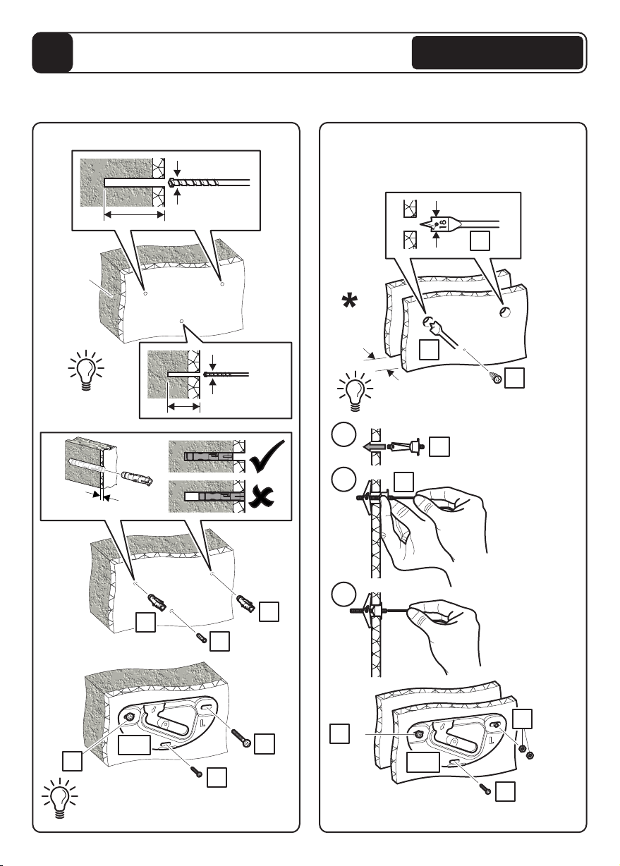
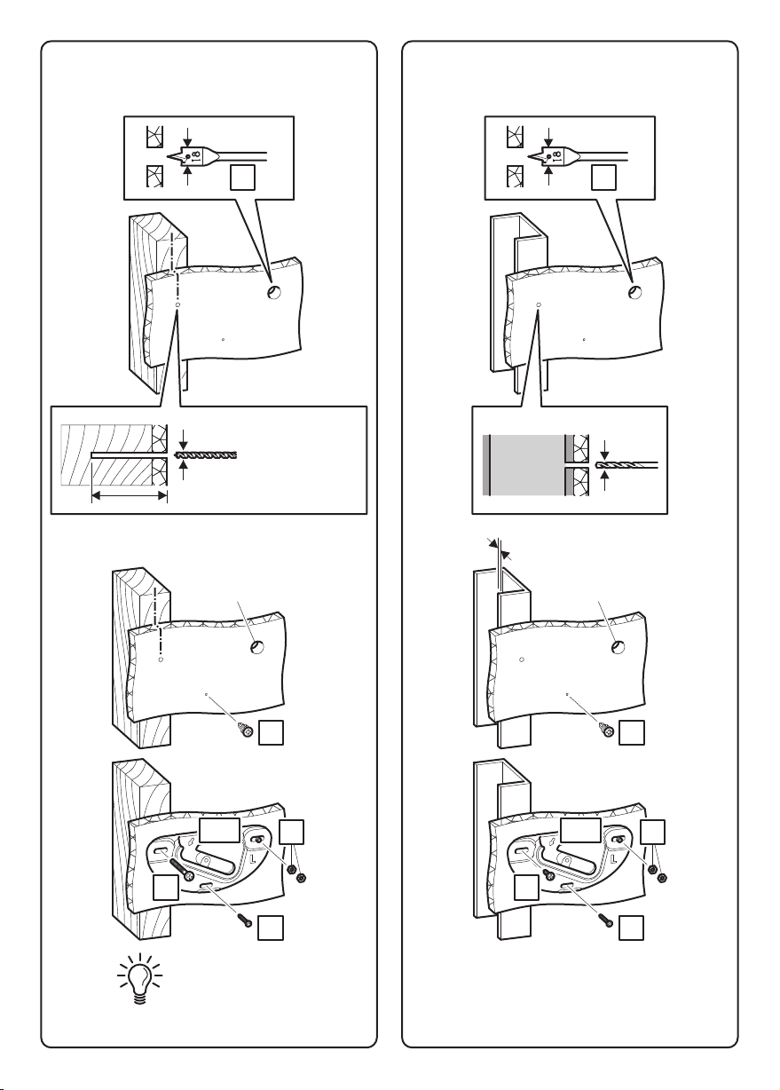
Fitting the Wall Bracket
6
Use the correct fixings for your wall type. Mixing fixing screws may be required for
installations that span different wall types. DO NOT OVER TIGHTEN SCREWS.
Solid Wall
10mm (25/64")
40mm (19/16")
5.5mm (7/32")
N
O
N
M
Q
M
Remove dust
from holes
Lubricate screw
thread with soap
12.5 mm (½") MAX
75mm (3")
A+B
Solid
Concrete
Drywall
18mm (3/4")
R
R
40mm
(19/16")
MIN gap
Remove dust from holes
A+B
O
Jx2
J
PSelf
drilling
i
ii
iii
H
S
Min supporting surface specification:- ½” thick
drywall, mounted on 1½” x 3½” wood stud at
16" centers.
Turn until
secure do not
over tighten
With Adaptor
Wood Stud Metal Stud
18mm (3/4") 18mm (3/4")
R R
3mm
(1/8") 3.5mm
(9/64")
75mm (3")
Ensure hole is
in the middle of
the wood stud
P P
Self
drilling
Self
drilling
Use Drywall Fixing H
O O
Lubricate screw
thread with soap
A+B A+B
J J
N L
Only one fixing will be in the wood stud. The
other fixings will be in drywall (see above)
Only one fixing will be in the metal stud. The
other fixings will be in drywall (see above)
Min supporting surface specification:-
½” thick drywall
Use Drywall Fixing H
0.6mm (0.025") MIN stud thickness
Min supporting surface specification:-
½” thick drywall
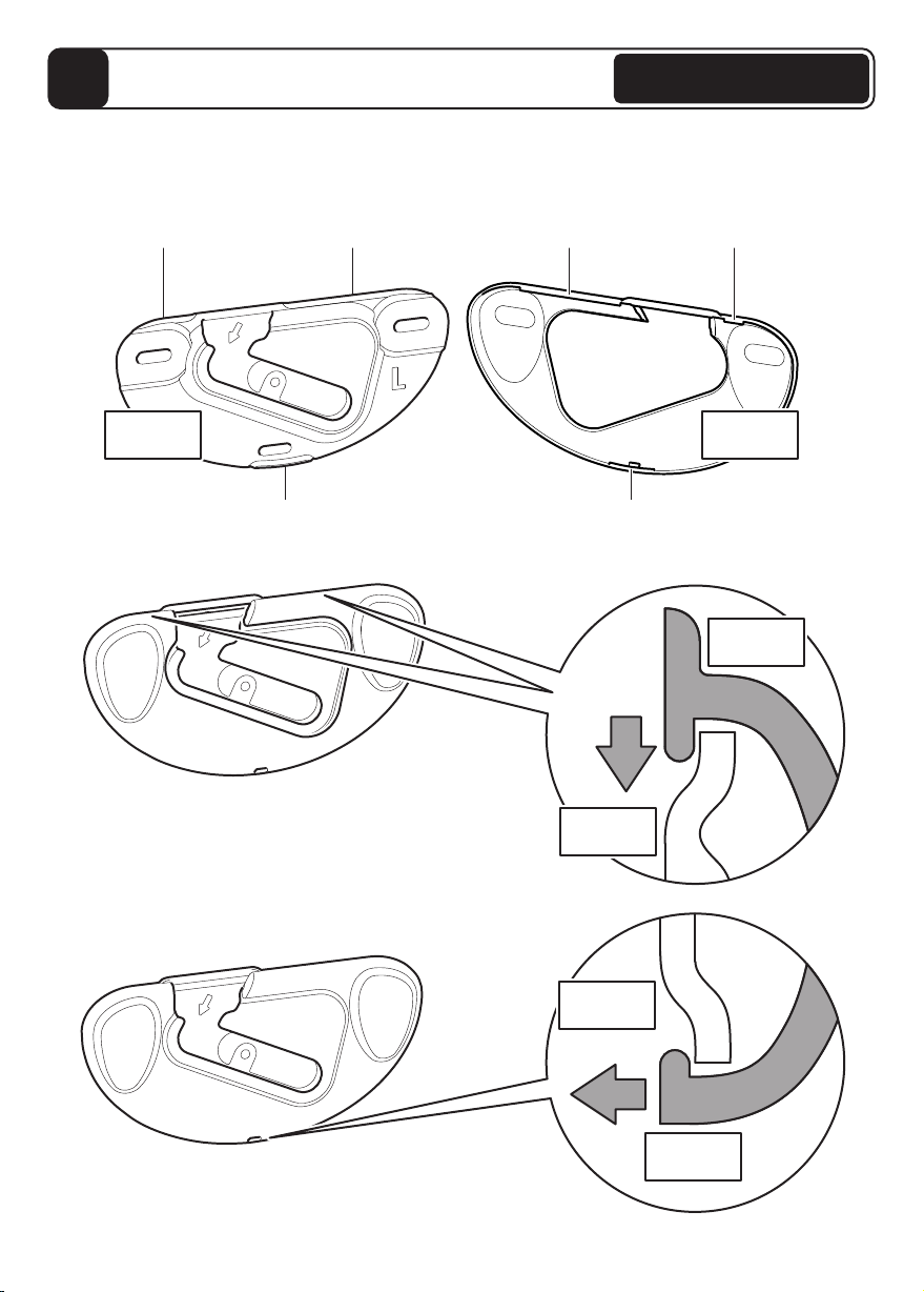
Fitting the Wall Bracket Covers
7
A1+B1
On wall bracket covers A1 & B1 are 3 retaining tabs. These locate onto 3 retaining lips
on wall brackets A & B and lock the wall bracket covers in position.
Retaining tab
Retaining tab
Retaining tab
A+B
Retaining lip
Retaining lip
Retaining lip
A1+B1
A+B
A1+B1
A+B
With Adaptor
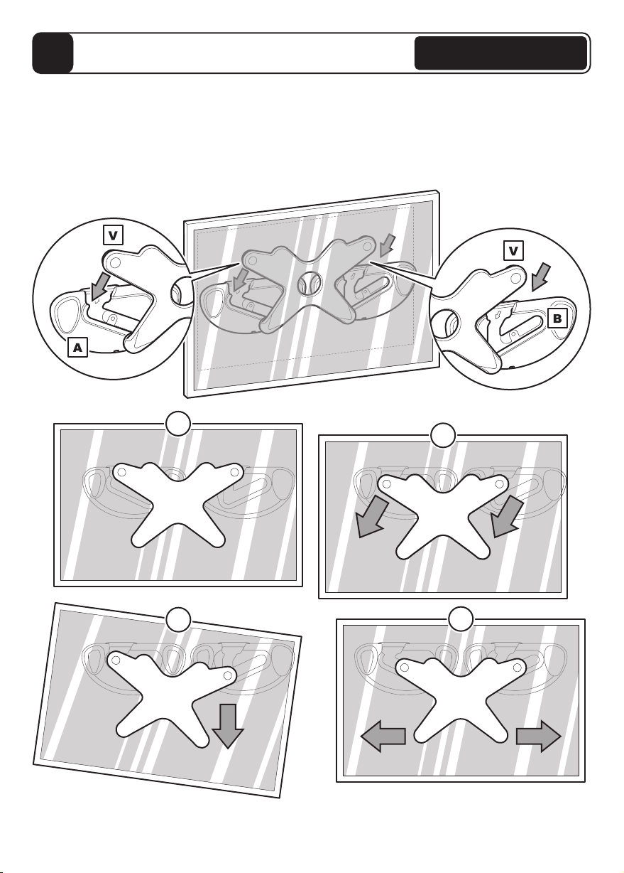
Hanging the TV
8
If required you can adjust the level
of your TV by moving from side to side
Removing the TV
This is a two person job. To remove the TV reverse the movements as shown above.
Hanging the TV is a two person job.
Present adaptor V (on the back of the TV) to the opening on brackets A & B. Slide down
and across into place. Ensure adaptor is fully engaged. If cables from the TV
prevent the TV resting against the wall then an alternative hanger configuration will be
required (see section 2).
iii
iii iv
With Adaptor
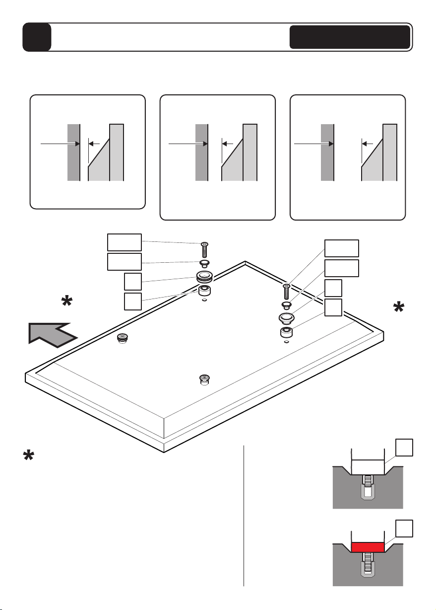
Fit Screen Hangers to TV
9
Once you have established which screw diameter you need for your TV you will need to choose
which wall spacing you require. Check the back of your TV and use the OPTION that fits your TV.
Please see page opposite for more details.
OPTION 1
12mm Wall Space
OPTION 2
20mm Wall Space
OPTION 3
40mm Wall Space
Suitable for TVs with a flat
back and no obstructions
Suitable for TVs with small
to medium obstructions eg
power supply, mouldings etc
Suitable for TVs with large
obstructions eg power
supply, mouldings etc
12mm 20mm 40mm
TV TV TV
Top
Bottom Fixings
If required
Top Fixings
F1-F3
G1-G12
C
If required E1
G1-G12
If required
F1-F3
D
If required
E1
E2
TV
TV
Problem
Not enough screw
engagement
Solution
Red spacer
has replaced
spacer
E2
E1
E1
In certain circumstances it may be necessary to use
red spacer E2 as either a replacement or addition to
spacer E1.
When is it necessary to use red spacers E2?
It is recommended that when fitting Hangers C and
Stand-offs D to your TV you have at least 5-10mm of
screw engagement. In certain circumstances you may
need to use red spacers E2 as either a replacement,
or together with spacers E1 to achieve this. Whenever
you use red spacers E2 you must use all 4 provided.
Without Adaptor
C C CDD D
E1E1E1E1E1E1
E1E1E1E1E1E1
E1E1E1E1E1E1
F2F3F2F3
G6G6G9G9G12 G12
C D
C DC D
E1E1
E1E1E1E1
F2F3
G5G8G11
F2F3
G5G8G11
C DC DC DC D
F1F1F2F2F3F3
G1G1G4G4G7G7G10 G10
OPTION 1
12mm Wall Space
Top Fixings
M4 M5 M6 M8
Bottom Fixings
M4 M5 M6 M8
TopFixings
M5 M6 M8
Bottom Fixings
M5 M6 M8
Top Fixings
M5 M6 M8
Bottom Fixings
M5 M6 M8
This OPTION is not suitable
for M4 screws G1-3
OPTION 2
20mm Wall Space
This OPTION is not suitable
for M4 screws G1-3
OPTION 3
40mm Wall Space
Assemble Positioning Template
10
U2
U1
Determine Bracket Hole Centers
11
Top
The center line of the
template U2 represents
the center of your TV.
Lay the template on the back of the TV and follow the instructions below.
Line up with top
of the screen.
Cut the template U2 so it is flush with
the bottom of your TV so that when the
template is on the wall you can see
exactly where your TV will be vertically
(distance from the floor and ceiling).
If hangers C do not line up with any holes on the template then ensure template is
firmly in position and punch 2 holes to match your top fixing centers with a pencil or
sharp object.
U1
U2
CPlace the top row of holes on
template U1 over hangers C.
Mark off the top fixing centers
Top row holes
Without Adaptor
Without Adaptor
Marking Wall For Drill Points
12
Use your template to mark
two points on the wall that
correspond with the top
fixing centers of your TV.
Represents the
top of your TV. T
Represents the
bottom of your TV.
Represents the
center of your TV.
DRILL POINTS
T
Next, use the Wall Brackets and as a template and position them over the appropriate
PENCIL MARKS you have made, so that the mark is in the middle of the
CENTRAL HOLE of the Wall Bracket. Ensure the bracket is level and mark the three
DRILL POINTS with a pencil. Repeat for other bracket.
A B
Drill six 3mm pilot holes and select appropriate fixings (see section 6)
B
DRILL POINTS
A B
A
Before marking the wall,
determine the wall type that
you have (i.e. Solid Wall/
Drywall/Wood Stud/
Metal Stud).
Ensure the drilling area is
free from mains services
(Gas/Electric/Water).
Represents the
centre of your TV.
PENCIL MARK
CENTRAL HOLE
PENCIL MARK
CENTRAL HOLE
Without Adaptor

Fitting the Wall Bracket
13
Use the correct fixings for your wall type. Mixing fixing screws may be required for
installations that span different wall types. DO NOT OVER TIGHTEN SCREWS.
Solid Wall
10mm (25/64")
40mm (19/16")
5.5mm (7/32")
N
O
N
M
Q
M
Remove dust
from holes
Lubricate screw
thread with soap
12.5 mm (½") MAX
75mm (3")
A+B
Solid
Concrete
Drywall
18mm (3/4")
R
R
40mm
(19/16")
MIN gap
Remove dust from holes
A+B
O
Jx2
J
PSelf
drilling
I
ii
iii
H
S
Min supporting surface specification:- ½” thick
drywall, mounted on 1½” x 3½” wood stud at
16" centers.
Turn until
secure do not
over tighten
Without Adaptor
This manual suits for next models
1
Table of contents
Other AVF TV Mount manuals


