AVF Group 471748 User manual

60kg
132lb
Please read these instructions thoroughly before installation.
If you have any questions or need
spare parts don’t worry, we’re happy to help.
471748 Rev01
AVF Group Ltd. Hortonwood 30, Telford, Shropshire, TF1 7YE, England
Customer Helpline Online Support
0333 320 0463 www.avfgroup.com/support
Helpine Open Mon to Thurs 9am - 5pm, Fri 9am - 4pm

LIFETIME WARRANTY
A
VF warrants that the product isfree from defects inmaterial and workmanship, as long as the product is
o
wned by the original consumer purchaser. If, during the stated warranty of this product, it proves to be
d
efective, AVF will remedy the defect by either repairing or replacing the defective part or, replacing the
e
ntire product. Proof of original purchase is required and should be retained.
A
VF reserve the right to substitute replacement products to others of similar value and design (Usually inthe
e
vent of discontinued product models).
A
VF accept no responsibility for failures / loss which result from misuse, negligence, accident, improper
ass
embly orinstallation or other causesbeyond AVF’s reasonable control and also excludes and will not pay
a
ny incidental and consequential damages.
INS
TALLATION: This product is sold as a home DIY product and as such, it is the responsibility of the install
er
t
o ensure that the product is correctly installed. AVF accept no responsibility if the product isincorrectly
i
nstalled.
This product is intended for indoor use only. Use of this product outdoors could lead to failure and personal
injury.
IF
YOU ARE IN ANY DOUBT, CONSULT A QUALIFIED CONTRACTOR.
N
OTES
W
ALLS: It is the responsibility of the installer to ensure that the wall is of a suitable standard and void of any
se
rvices (eg gas, electricity, water etc). AVF accept no responsibility for any damage or loss caused by
in
stalling this product in a sub standard wall.
W
ALL FIXINGS: Wall fixings are supplied for wood, brick, solid masonry and also, for some specific
products, fixings are supplied for fixing to plasterboard.
D
O
-
Retain all packaging in case the bracket needs to be returned.
-
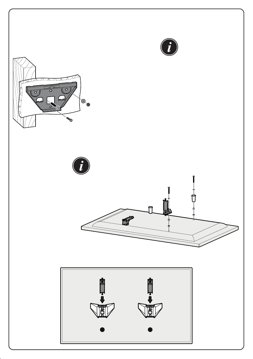
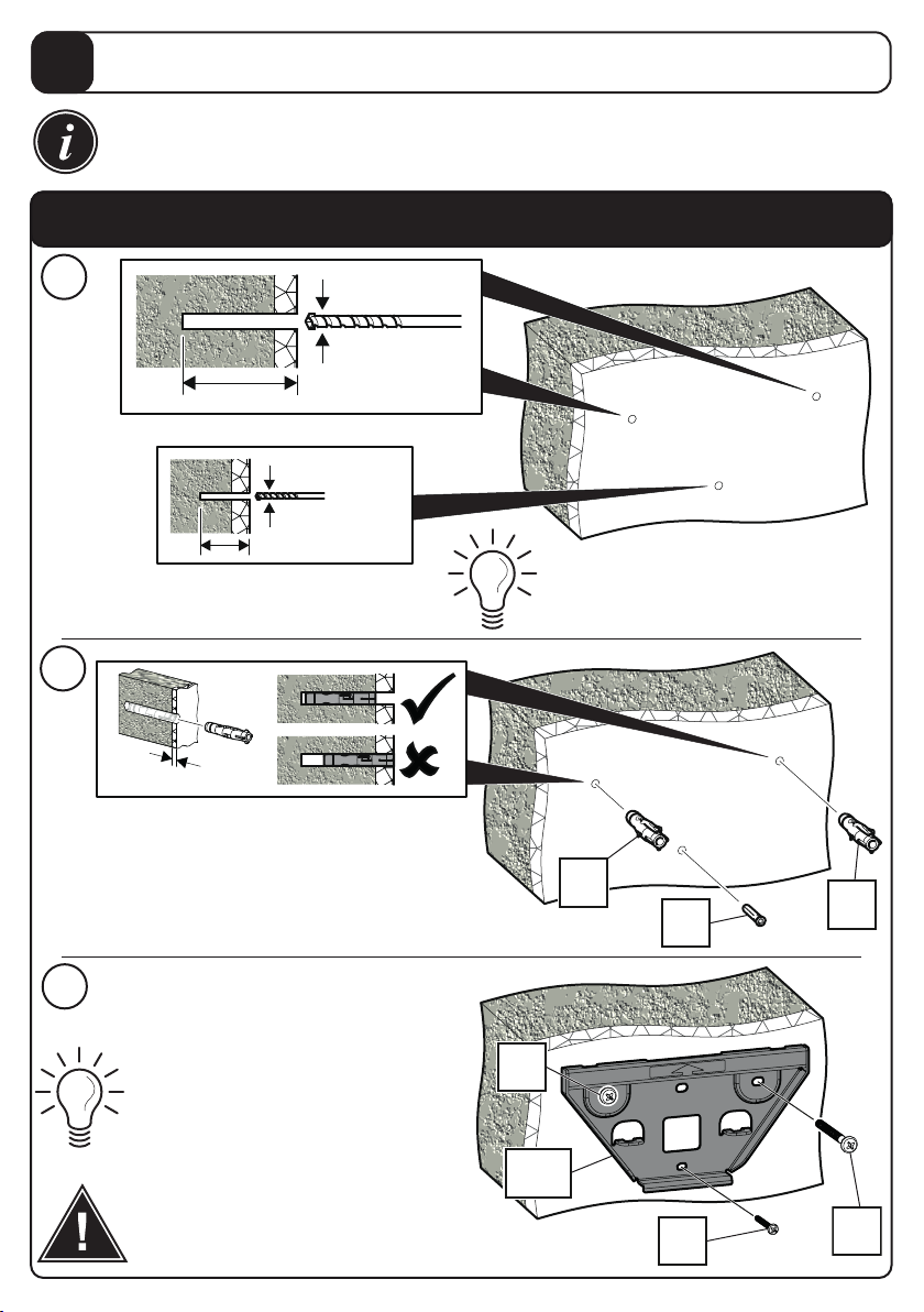
When fastening to wood studs, be sure to pre-drill holes into the wood stud.
-
When fastening to brick or solid masonry, drill the holes in accordance with the instructions. Always remove
d
rill dust from the hole before inserting the wallplug.
-
Wall plug body must be fully inserted into the wall (ie fully into the brick).
-
Lubricate the wall screws withsoap to ease installation.
- Check the strength of the installation before fitting the TV.
-
Periodically check strength of installation, signs of corrosion, damage or loose components.
D
ON’T
-
Do not set in mortar joints.
-
Do not over tighten screws.
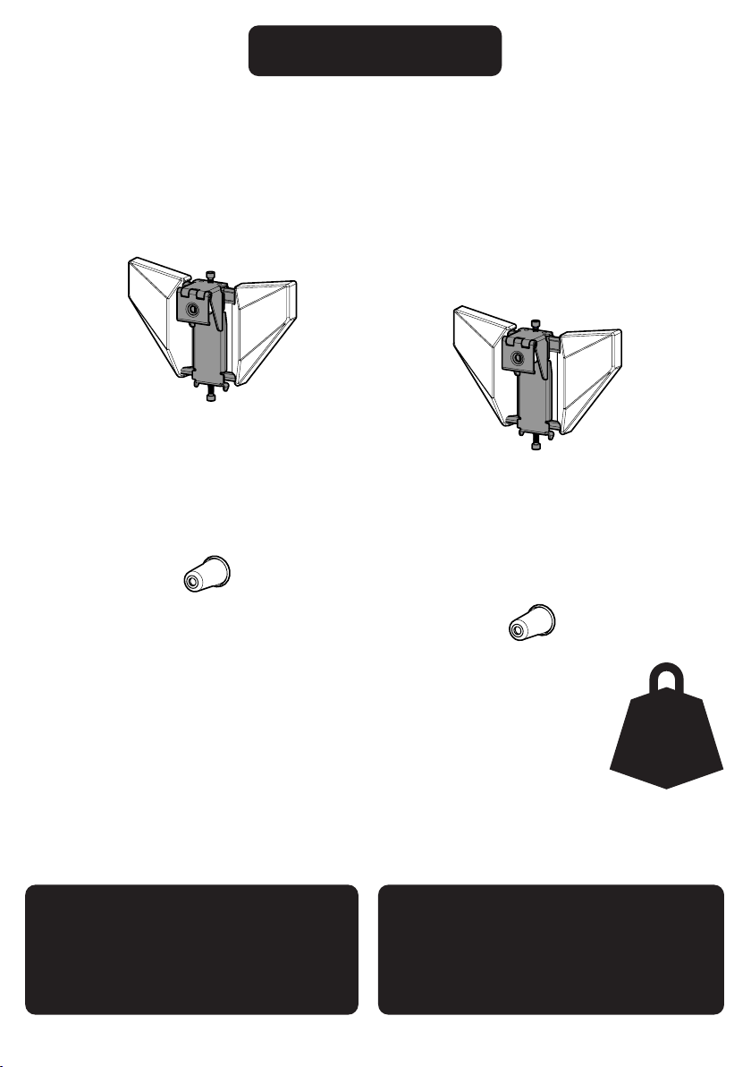
T
V HANGING
M
ust be carriedout using the manufacturers threaded holes intended for this purpose. All variables of TV
han
ging screws are supplied within the product box (Because of the universal nature of this product, expect
t
ohave excessparts left over following your installation).
I
t is the responsibility of the installer to ensure the correct TV hanging screws are selected. If indoubt consul
t
t
he TV manufacturer. AVF accept no responsibility for any damage caused by the use of the incorrect TV
hanging screw or the use of incorrect fixing holes.
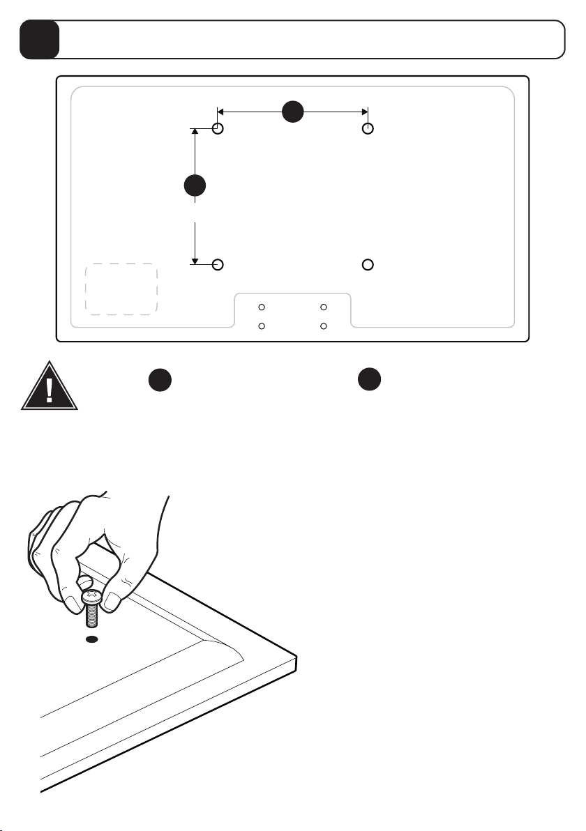
!PLEASE REVIEW ALL NOTES AND PRODUCT INSTRUCTIONS BEFORE
COMMENCING THE INSTALLATION.
WARRANTY INFORMATION

Index
Marking Wall for Drill Points
2
Measure the TV fixing holes Width and Height
1
Retain all packaging in case the product needs to be returned.
Contents may vary from photography / illustrations.
You will not need all these parts, so expect there to be some left over depending upon the
specification of your TV.
This product is intended for indoor use only. Use of this product outdoors could lead to
failure and personal injury.
It is the responsibility of the installer to ensure that the mounting wall is of a suitable
standard and void of any services (eg gas, electricity, water etc).
AVF accept no responsibility for any damage or loss caused by installing this product in a
substandard wall.
Fitting the Wall Brackets
3
Hanging the TV
7
Tools Recommended
Stud Finder
Ø3mm (1/8”) Wood
Ø
10mm (25/64”) Masonry
Ø
5.5mm (7/32”) Masonry
Fit Screen Hangers to TV
6
Fitting the Wall Bracket Covers
4
Levelling the Screen Hangers
5
Drill bits required will
depend on wall type.

Boxed Parts
Gx4 Nx4
Mx4
Ix4 Q
3mm
RL x2
Kx2
Px4
Ox4
Hx4
Jx2
A1x2
A2x2
Bx2
Cx2

T1
T2
F1
x4
F3
x4
F4
x4
D1
x8
D2
x4
E1
x4
E2
x4
E3
x4
F2
x4
F5
x4
F6
x4
50mm
25mm
M4 M6 M8
TV Screws, Reducers and Spacers
S1S3
S2

Assembly Overview
Fitting the Wall Bracket
Fit Screen Hangers to TV
Hanging the TV
This product comes with screws to fit a huge range
of TVs. You will have a lot of screws left over. We
recommend keeping them in a safe place in case you
change your TV in the future.
This product is suitable for attaching to plasterboard,
wood stud, brick, dot and dab, concrete, or any
combination of these wall types. Establish which
wall type you are mounting to and follow the
corresponding steps.
This product comes with fixings for all the wall types
mentioned above. You will have lots of wall fixings
left over. We recommend keeping them in a safe
place in case you want to move your TV to a different
wall type in future.

Measure the TV fixing holes Width and Height
1
Determine which diameter TV Screws
fit your TV and put them to one side.
M4, M6 or M8
We will select the correct length later.
If width ais less than 200mm or height bless than 100mm
STOP installation now and contact the customer helpline.
200mm to infinity
a
b
100mm to infinity

Marking Wall for Drill Points
2
T1
T2
The centre line of the
template T2 represents
the centre of your TV.
Line up with top
of the screen.
Top of TV
Top Row Holes
Place the top row of holes on
template T1 over the top fixing
holes on your TV. Mark off the
top fixing centres.
Cut the template T2 so it is flush with
the bottom of your TV so that when the
template is on the wall you can see
exactly where your TV will be vertically
(distance from the floor and ceiling).
If the top fixing holes on your TV do not line up with any holes on the template then
ensure template is firmly in position and carefully punch holes to match your top fixing
centres with a pencil or sharp object. Remove the template from the TV and carefully
punch holes for top and bottom wall bracket centre holes to match your TV fixing holes.
Lay the template on the back of the TV and follow the instructions below.
T1
T2
Assemble the Positioning Template.
i
Determine Bracket Holes Centres.
ii
TV VESA Holes
Bracket Top
Central Hole
Bracket Bottom
Central Hole

Pencil Mark
Top Central Hole
Drill Points
Bottom Central Hole
Pencil Mark
Before marking the wall, determine the wall type that you have (i.e. Solid Wall/
Dot & Dab/Plasterboard/Wood Stud/Metal Stud). Ensure the drilling area is free
from mains services (Gas/Electric/Water).
Before you drill make sure you are happy with the position and ensure all markings are
correct and level.
Represents the
top of your TV.
Represents the
centre of your TV.
Represents the
bottom of your TV.
Use your template to mark
two points on the wall that
correspond with the top
and bottom central holes
on your wall bracket.
Next, use the Wall Brackets A1 as a template and position them over the appropriate
PENCIL
MARKS you have made, so that the marks are in the middle of the TOP AND BOTTOM
CENTRAL HOLES of the Wall Bracket. Ensure the bracket is level and mark the three DRILL
POINTS with a pencil. Repeat for other bracket.
Marking the Wall.
iii
A1

Solid Wall
10mm (25/64")
75mm (3") MIN
40mm (1 ") MIN
9/16
5.5mm (7/32")
12.5 mm (½") MAX
P
L
P
O
K
O
A1
Remove Dust from Holes.
Lubricate screw thread with soap.
DO NOT overtighten screws.
Tighten screws by hand only
i
ii
iii
This product is designed to be fitted to many different types of wall. Identify
your wall type and follow the relevant instruction. Make sure you use the
correct fixings for your wall.
Fitting the Wall Brackets
3

If gap is above 40mm (1 ") use
plasterboard fixing method.
9/16
9/1640mm (1 ")
MAX gap.
10mm (25/64")
108mm (4 ") MIN
1/4
Dot and Dab
N
J
N
M
K
M
A1
Remove Dust from Holes.
Lubricate screw thread
with soap.
DO NOT overtighten screws.
Tighten screws by hand only
i
ii
iii
If you have trouble fitting J
you can drill a 3mm pilot hole.

Plasterboard
9/1640mm (1 ")
MAX gap.
H+I
J
K
A1
H
a
b
c
G
R
Q
18mm (3/4")
Q
I
Remove Dust from Holes.
Lubricate screw thread
with soap.
DO NOT overtighten screws.
Tighten screws by hand only
i
ii
iii
If you have trouble fitting J
you can drill a 3mm pilot hole.

18mm (3/4")
Q
Use Plasterboard
fixing G
Wood Stud
3mm (1/8")
75mm (3") MIN
Ensure hole is in
the middle of the
wood stud.
J
O
K
A1
H
I
Lubricate screw thread
with soap.
DO NOT overtighten screws.
Tighten screws by hand only
i
ii
iii
If you have trouble fitting J
you can drill a 3mm pilot hole.
Only one fixing will be in the
wood stud. The other fixings
will be in plasterboard (see
Plasterboard installation
instruction).

Fitting the Wall Bracket Covers
4
A1
A1
A2
A2
Fit the wall bracket covers by pushing covers A2 on to the wall
brackets A1 until they click in to place.

Levelling the Screen Hangers
5
B
B
Slide hangers Bin to position on each wall bracket.
Use a spirit level across the tops of the hangers to check they
are level. If the spirit level isn’t long enough, place a flat piece
a wood across the tops of the hangers first.
If the hangers aren’t level, tighten the levelling screw on the
lower hanger until they are.
S1

Fit Screen Hangers to TV
6
B
B
Top
of TV
Bottom
of TV
B
B
Make sure you connect the Screen Hangers in the correct position after
you have levelled them. This will ensure the TV is level when you hang
it on the wall.
Flip open the hangers to access the
screw hole when fitting to the back
of the TV.

After completing this step, you will
have lots of TV screws left over.
Keep them in a safe place in case
you require them in future.
Bottom
of TV
Top
of TV
Use with Screws
F1 or F2.
E
1
E
2
E
3
Use with Screws
F3 or F4.
Use with Screws
F5 or F6.
F1- F6
TV TV TV
Select the correct length TV screw.
D1
D2
You may need to use Spacers D1 or D2
if the screws are too long or the back of
your TV is not flat.
You can also use longer screws and the
spacers to increase the distance of the
TV from the wall.
If required
TV
B
C
Use the same combination of screws,
washers and spacers in all
four TV fixing holes.

Hanging the TV
7
View “through” TV from the front.
Side View
Do not tilt the TV when hanging. The TV must
be vertical (parallel to the wall) when hooking
in to place.

S1
S3
S2
Removing the TV
To remove the TV reverse the hanging procedure.
Do not tilt the TV when removing.
Lift the TV straight up, ensuring it stays vertical (parallel to the wall).
Locking the TV
You can carefully pull the bottom of the TV away from the wall, and hold
it in position, to gain better access to the TV Locking Screws.

Cable Access
For easy cable access, gently pull the bottom of the TV away from the wall using two
hands. Hold the TV in position while accessing cables. When finished gently lower the
TV back to against the wall.
Stop before the top of
the TV touches the wall.
TV Levelling (optional)
If your TV needs levelling, only adjust the TV Levelling Screw on the low
side of the TV. For example, if the right hand side of your TV is low, tighten
the right hand TV Levelling Screw only, until your TV is level.
S1
For larger TVs you may need to use the extended Allen Key
in order to reach the TV Level Adjustment Screws.
Table of contents
Other AVF Group TV Mount manuals

AVF Group
AVF Group NZL8500 User manual

AVF Group
AVF Group 469897 User manual

AVF Group
AVF Group 471758 User manual

AVF Group
AVF Group 469193 User manual

AVF Group
AVF Group JML8650 User manual

AVF Group
AVF Group ZML8360 User manual

AVF Group
AVF Group P6491 Manual

AVF Group
AVF Group 471819 User manual

AVF Group
AVF Group NML200 Manual

AVF Group
AVF Group 471991 User manual