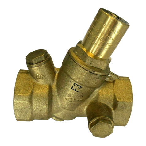
Pressure Adjustment
The Pressure reducing valve has been factory set to 500kPa and has an adjustment range
of 250 - 750kPa.
To adjust the pressure:
1. Ensurethelineshavebeenushedandtheairpurgedfromthesystem.
2. Turnthewateroandrelievethepressurefromthesystem.
3. Removethetestpointpluglocatedontheoutletsideofthevalveandtyourtest
gauge.
4. Turn the water on and observe the gauge pressure.
5. Using a screw driver turn the screw clockwise to increase the pressure and anti-
clockwise to decrease the pressure.
6. During this process it may be necessary to open a tap on the line and allow water to
runandthenclosethetaptoconrmyouradjustment.Checkyourtestgaugeand
repeat if necessary.
7. Repeatsteps2and3andremovetestgaugeandre-ttestpointplug.
8. Make sure all joints are water tight and check for leaks.
Installation
The Pressure reducing valve must be installed by a licensed plumber and in
accordance with AS/NZS 3500, relevant local requirements and the following
manufacturer’s instructions.
Important Note
Flush out your lines to remove any debris or dirt particles that may cause the
valve to malfunction.
1. The pressure reducing valve may be installed horizontally or vertically.
2. It is recommended that isolation valves be fitted either side of the
Pressure reducing valve to assist future maintenance operations.
3. The PRV15 and PRV20 are protected by an internal stainless steel mesh
filter. If the valve is being installed in an environment where fine dirt
particles are present it is recommended that a line strainer be fitted
upstream of the valve.
4. Ensure that the valve is installed in an accessable position for future
maintenance operations.
5. Install the valve with the arrow on the valve body pointing in the direction
of flow.
For best operation the inlet pressure should be at least 150 kPa higher than the
outlet pressure.
Recommendations for installation
1. Do NOT install PRV’s below ground.
2. If the installation is at risk of water hammer, fit a water hammer arrestor.
3. If the pressure setting is important for the protection of equipment fit a
pressure relief valve downstream of the valve.
Installation Diagram
Pressure Adjustment
The Pressure reducing valve has been factory set to 500kPa and has an
adjustment range of 150 - 600kPa
To adjust the pressure:
1. Ensure the lines have been flushed and the air purged from the system.
2. Turn the water off and relieve the pressure from the system.
3. Remove the test point plug located on the outlet side of the valve and fit
your test gauge.
4. Turn the water on and observe the gauge pressure.
5. Remove the factory set pressure sticker located on top of the valve cover
and expose the adjustment screw.
6. Using a screw driver turn the screw clockwise to increase the pressure and
anti-clockwise to decrease the pressure.
7. During this process it may be necessary to open a tap on the line and
allow water to run and then close the tap to confirm your adjustment.
Check your test gauge and repeat if necessary.
8. Repeat steps 2 and 3 and remove test gauge and re-fit test point plug.
9. Make sure all joints are water tight and check for leaks.
Adjustment Diagram
Trouble Shooting
Reduced Flow Rate.
This problem is caused by a build up of foreign material on the gauze filter inside
the valve (see maintenance procedures)
The Pressure Reducing Valve does not maintain its set pressure.
This problem is caused by a build up of foreign material on the valve seat. This
prevents the valve from shutting off causing leakage with a resulting increase in
pressure down stream. (see maintenance procedures to clean or replace cartridge)
• Drain lines must have a continuous fall
Adjustment Diagram
CAUTION!
If the pressure reducing valve is not installed, commissioned and maintained properly in
accordance with the instructions contained in this manual, it may not operate correctly,
and cause damage to objects and or persons.
Disclaimer: Every care has been taken in the preparation of these instructions, which have been issued as a guide only. Compliance
with the requirements of local Authorities is required at all times. These requirements may change from time to time. Always be aware
of local requirements. Subject to any statutory obligations and manufacturers warranties no liability can be accepted for any losses,
consequential or otherwise which may arise or be said to have arisen from relying upon the contents of this installation instruction as to
thetnessofanyparticularproductforanyparticularpurpose,useorapplication.TheAustralianValveGroupPtyLtdreservestherightto
modifydesignsandspecicationsandtowithdrawandintroduceproductsatanytimewithoutnotice.
Leave this operating manual with the user
01/21
Unit 2, 9-11 Noble St, Kewdale, WA, 6105
Tel: 1800 AVG AUS (284 287) Fax: (08) 9353 2689
www.avg.net.au


