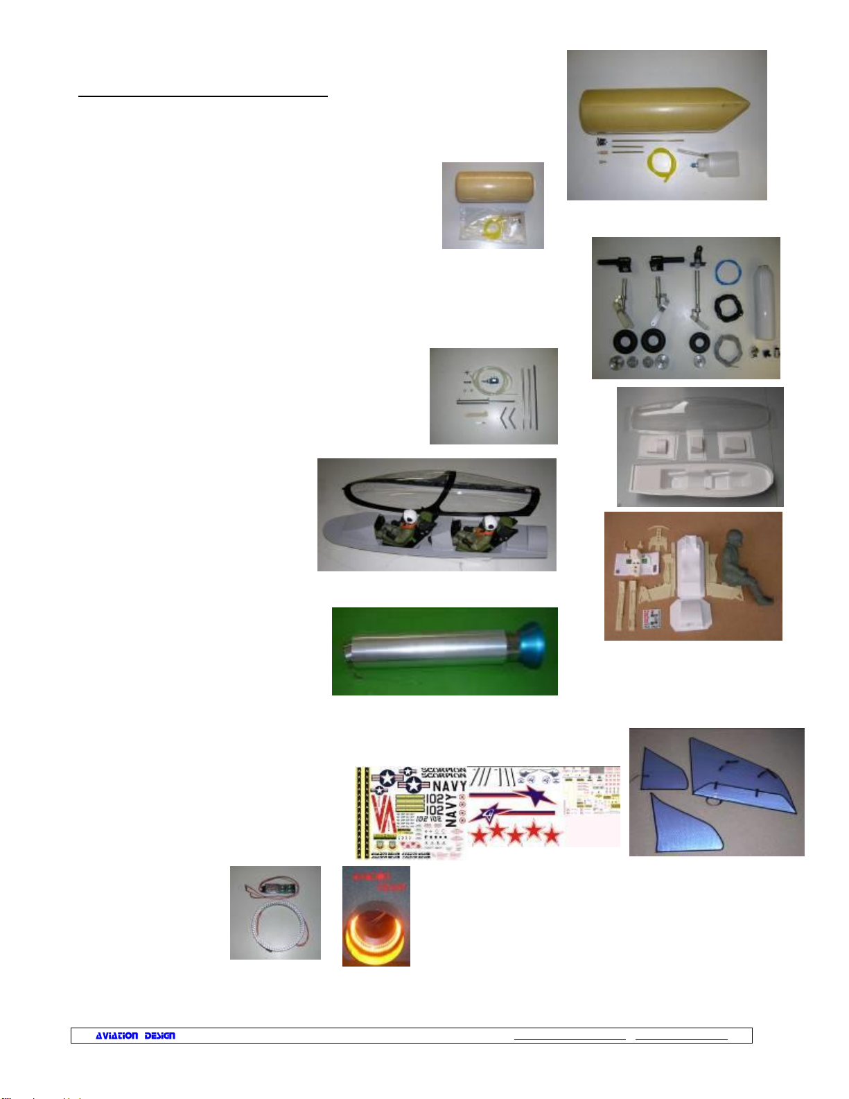
Aviation Design super scorpion User manual
Other Aviation Design Toy manuals

Aviation Design
Aviation Design Diamond User manual

Aviation Design
Aviation Design super scorpion User manual

Aviation Design
Aviation Design F-16 User manual

Aviation Design
Aviation Design SPITFIRE MK IX User manual

Aviation Design
Aviation Design STORM User manual

Aviation Design
Aviation Design Mini Diamond User manual

Aviation Design
Aviation Design SUKHOI SU-27 User manual

Aviation Design
Aviation Design Falcon 7X User manual

Aviation Design
Aviation Design Angel User manual

Aviation Design
Aviation Design sukhoi su-35 User manual


Popular Toy manuals by other brands

FUTABA
FUTABA GY470 instruction manual

LEGO
LEGO 41116 manual

Fisher-Price
Fisher-Price ColorMe Flowerz Bouquet Maker P9692 instruction sheet

Little Tikes
Little Tikes LITTLE HANDIWORKER 0920 Assembly instructions

Eduard
Eduard EF-2000 Two-seater exterior Assembly instructions

USA Trains
USA Trains EXTENDED VISION CABOOSE instructions